

Space Shuttle external tank
Encyclopedia
Space Shuttle
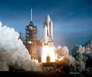
The Space Shuttle was a manned orbital rocket and spacecraft system operated by NASA on 135 missions from 1981 to 2011. The system combined rocket launch, orbital spacecraft, and re-entry spaceplane with modular add-ons...
launch vehicle that contains the liquid hydrogen
Liquid hydrogen
Liquid hydrogen is the liquid state of the element hydrogen. Hydrogen is found naturally in the molecular H2 form.To exist as a liquid, H2 must be pressurized above and cooled below hydrogen's Critical point. However, for hydrogen to be in a full liquid state without boiling off, it needs to be...
fuel and liquid oxygen
Liquid oxygen
Liquid oxygen — abbreviated LOx, LOX or Lox in the aerospace, submarine and gas industries — is one of the physical forms of elemental oxygen.-Physical properties:...
oxidizer. During lift-off and ascent it supplies the fuel and oxidizer under pressure to the three Space Shuttle Main Engine
Space Shuttle main engine
The RS-25, otherwise known as the Space Shuttle Main Engine , is a reusable liquid-fuel rocket engine built by Pratt & Whitney Rocketdyne for the Space Shuttle, running on liquid hydrogen and oxygen. Each Space Shuttle was propelled by three SSMEs mated to one powerhead...
s (SSME) in the orbiter
Space Shuttle Orbiter
The Space Shuttle orbiter was the orbital spacecraft of the Space Shuttle program operated by NASA, the space agency of the United States. The orbiter was a reusable winged "space-plane", a mixture of rockets, spacecraft, and aircraft...
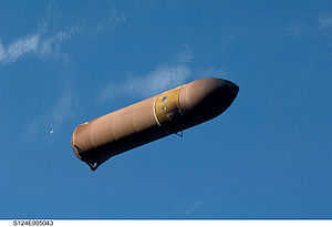
. The ET is jettisoned just over 10 seconds after MECO (Main Engine Cut Off), where the SSMEs are shut down, and re-enters the Earth's atmosphere. Unlike the Solid Rocket Boosters
Space Shuttle Solid Rocket Booster
The Space Shuttle Solid Rocket Boosters were the pair of large solid rockets used by the United States' NASA Space Shuttle during the first two minutes of powered flight. Together they provided about 83% of liftoff thrust for the Space Shuttle. They were located on either side of the rusty or...
, external tanks have not been re-used. They break up before impact in the Indian Ocean
Indian Ocean
The Indian Ocean is the third largest of the world's oceanic divisions, covering approximately 20% of the water on the Earth's surface. It is bounded on the north by the Indian Subcontinent and Arabian Peninsula ; on the west by eastern Africa; on the east by Indochina, the Sunda Islands, and...
(or Pacific Ocean
Pacific Ocean
The Pacific Ocean is the largest of the Earth's oceanic divisions. It extends from the Arctic in the north to the Southern Ocean in the south, bounded by Asia and Australia in the west, and the Americas in the east.At 165.2 million square kilometres in area, this largest division of the World...
in the case of direct-insertion launch trajectories, which are currently utilized) away from known shipping lanes. The tanks are not recovered.
There have been plans to use external tanks for other purposes, such as incorporation into a space station.
Overview
- the forward liquid oxygenOxygenOxygen is the element with atomic number 8 and represented by the symbol O. Its name derives from the Greek roots ὀξύς and -γενής , because at the time of naming, it was mistakenly thought that all acids required oxygen in their composition...
(LOX) tank - an unpressurized intertank that contains most of the electrical components
- the aft liquid hydrogenHydrogenHydrogen is the chemical element with atomic number 1. It is represented by the symbol H. With an average atomic weight of , hydrogen is the lightest and most abundant chemical element, constituting roughly 75% of the Universe's chemical elemental mass. Stars in the main sequence are mainly...
(LH2) tank; this is the largest part, but it is relatively light, due to hydrogen's very low density.
The ET is the "backbone" of the shuttle during launch, providing structural support for attachment with the solid rocket boosters (SRBs) and orbiter. The tank is connected to each SRB at one forward attachment point (using a crossbeam through the intertank) and one aft bracket, and it is connected to the orbiter at one forward attachment bipod and two aft bipods. In the aft attachment area, there are also umbilicals
Umbilical cable
An umbilical cable or umbilical is a cable which supplies required consumables to an apparatus. It is named by analogy with an umbilical cord...
that carry fluid
Fluid
In physics, a fluid is a substance that continually deforms under an applied shear stress. Fluids are a subset of the phases of matter and include liquids, gases, plasmas and, to some extent, plastic solids....
s, gas
Gas
Gas is one of the three classical states of matter . Near absolute zero, a substance exists as a solid. As heat is added to this substance it melts into a liquid at its melting point , boils into a gas at its boiling point, and if heated high enough would enter a plasma state in which the electrons...
es, electrical signals and electrical power between the tank and the orbiter. Electrical signals and controls between the orbiter and the two solid rocket boosters also are routed through those umbilicals.
Versions
Over the years, NASA has worked to reduce the weight of the ET to increase overall efficiency. For each pound of weight reduction, the cargo-carrying capability of the shuttle spacecraft is increased almost one pound.Standard Weight Tank
The original ET is informally known as the Standard Weight Tank (SWT) and is fabricated from 2219 - a high strength aluminium-copper alloy used for many aerospace applications. The first two, used for STS-1STS-1
STS-1 was the first orbital flight of NASA's Space Shuttle program. Space Shuttle Columbia launched on 12 April 1981, and returned to Earth on 14 April, having orbited the Earth 37 times during the 54.5-hour mission. It was the first American manned space flight since the Apollo-Soyuz Test Project...
and STS-2
STS-2
STS-2 was a Space Shuttle mission conducted by NASA, using the Space Shuttle Columbia. The mission launched on 12 November 1981. It was the second shuttle mission overall, and was also the second mission for Columbia...
, were painted white to protect the tanks from ultraviolet light during the extended time that the shuttle spends on the launch pad prior to launch.
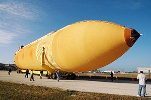
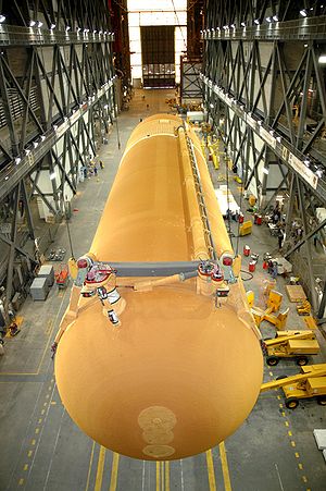
Because this did not turn out to be a problem and in order to reduce weight, Lockheed Martin ceased painting the external tanks beginning with STS-3
STS-3
STS-3 was NASA's third Space Shuttle mission, and was the third mission for the Space Shuttle Columbia. It was the first shuttle launch with an unpainted external tank, and the only mission to land at the White Sands Space Harbor near Las Cruces, New Mexico.-Crew:-Backup crew:-Mission...
, leaving the rust-colored spray-on insulation bare, saving approximately 272 kg (599.7 lb) of weight.
After STS-4
STS-4
STS-4 was a NASA Space Shuttle mission, using the Space Shuttle Columbia. The mission launched on 27 June 1982 and landed a week later on 4 July. STS-4 was the fourth shuttle mission overall, and was also the fourth mission for the Columbia.-Crew:...
, several hundred pounds were eliminated by deleting the anti-geyser line. This line paralleled the oxygen feed line, providing a circulation path for liquid oxygen. This reduces accumulation of gas
Gas
Gas is one of the three classical states of matter . Near absolute zero, a substance exists as a solid. As heat is added to this substance it melts into a liquid at its melting point , boils into a gas at its boiling point, and if heated high enough would enter a plasma state in which the electrons...
eous oxygen in the feed line during prelaunch tanking (loading of the LOX). After propellant
Propellant
A propellant is a material that produces pressurized gas that:* can be directed through a nozzle, thereby producing thrust ;...
loading data from ground tests and the first few space shuttle missions was assessed, the anti-geyser line was removed for subsequent missions. The total length and diameter of the ET remain unchanged. The last SWT tank, flown on STS-7
STS-7
STS-7 was a NASA Space Shuttle mission, during which Space Shuttle Challenger deployed several satellites into orbit. The shuttle launched from Kennedy Space Center on 18 June 1983, and landed at Edwards Air Force Base on 24 June. STS-7 was the seventh shuttle mission, and was Challengers second...
, weighed approximately 35000 kg (77,161.8 lb) inert.
Lightweight Tank
STS-6
STS-6 was a NASA Space Shuttle mission conducted using Space Shuttle Challenger, carrying the first Tracking and Data Relay Satellite, TDRS-1, into orbit. Launched on 4 April 1983, STS-6 was the sixth shuttle mission and the first of the ten missions flown by Challenger...
mission, a lightweight ET (LWT), was introduced. This tank was used for the majority of the Shuttle flights, and was last used on the ill-fated Space Shuttle Columbia disaster
Space Shuttle Columbia disaster
The Space Shuttle Columbia disaster occurred on February 1, 2003, when shortly before it was scheduled to conclude its 28th mission, STS-107, the Space Shuttle Columbia disintegrated over Texas and Louisiana during re-entry into the Earth's atmosphere, resulting in the death of all seven crew members...
(STS-107
STS-107
-Mission parameters:*Mass:**Orbiter Liftoff: **Orbiter Landing: **Payload: *Perigee: *Apogee: *Inclination: 39.0°*Period: 90.1 min- Insignia :...
). Although tanks vary slightly in weight, each weighed approximately 30000 kg (66,138.7 lb) inert.
The weight reduction from the SWT was accomplished by eliminating portions of stringers (structural stiffeners running the length of the hydrogen tank), using fewer stiffener rings and by modifying major frames in the hydrogen tank. Also, significant portions of the tank were mill
Milling machine
A milling machine is a machine tool used to machine solid materials. Milling machines are often classed in two basic forms, horizontal and vertical, which refers to the orientation of the main spindle. Both types range in size from small, bench-mounted devices to room-sized machines...
ed differently to reduce thickness, and the weight of the ET's aft solid rocket booster
Space Shuttle Solid Rocket Booster
The Space Shuttle Solid Rocket Boosters were the pair of large solid rockets used by the United States' NASA Space Shuttle during the first two minutes of powered flight. Together they provided about 83% of liftoff thrust for the Space Shuttle. They were located on either side of the rusty or...
attachments were reduced by using a stronger, yet lighter and less expensive titanium
Titanium
Titanium is a chemical element with the symbol Ti and atomic number 22. It has a low density and is a strong, lustrous, corrosion-resistant transition metal with a silver color....
alloy.
Super Lightweight Tank
The Super Lightweight Tank (SLWT) was first flown in 1998 on STS-91STS-91
STS-91 was the final Space Shuttle mission to the Mir space station. It was flown by Space Shuttle Discovery, and launched from Kennedy Space Center, Florida, on 2 June 1998.-Crew:-Mission parameters:*Mass:...
and was since used with only two exceptions (STS-99
STS-99
STS-99 was a Space Shuttle Endeavour mission, that launched on 11 February 2000 from Kennedy Space Center, Florida. The primary objective of the mission was the Shuttle Radar Topography Mission project.-Crew:-Mission parameters:*Mass:...
and STS-107
STS-107
-Mission parameters:*Mass:**Orbiter Liftoff: **Orbiter Landing: **Payload: *Perigee: *Apogee: *Inclination: 39.0°*Period: 90.1 min- Insignia :...
). The SLWT had basically the same design as the LWT except that it used an aluminum/lithium alloy
Al-Li
Al-Li alloys are a series of alloys of aluminium and lithium, often also including copper and zirconium. Since lithium is the least dense elemental metal these alloys are significantly less dense than aluminium...
(Al 2195) for a large part of the tank structure. This alloy provided a significant reduction in tank weight (~3,175 kg/7,000 lb) over the LWT. Although all ETs produced since the introduction of the SLWT were of the this configuration, one LWT remained in inventory to be used if requested until the end of the shuttle era. The SLWT provided 50% of the performance increase required for the shuttle to reach the International Space Station
International Space Station
The International Space Station is a habitable, artificial satellite in low Earth orbit. The ISS follows the Salyut, Almaz, Cosmos, Skylab, and Mir space stations, as the 11th space station launched, not including the Genesis I and II prototypes...
.
Technical specifications
SLWT Specifications- Length: 153.8 ft (46.9 m)
- Diameter: 27.6 ft (8.4 m)
- Empty Weight: 58500 lb (26,535.2 kg)
- Gross Liftoff Weight: 1680000 lb (762,035.2 kg)
LOX tank
- Length: 54.6 ft (16.6 m)
- Diameter: 27.6 ft (8.4 m)
- Volume (at 22 psigPounds per square inchThe pound per square inch or, more accurately, pound-force per square inch is a unit of pressure or of stress based on avoirdupois units...
): 19541.66 cu ft (146,181.8 US gal; 553,358.2 l) - LOX mass (at 22 psig): 1387457 lb (629,339.9 kg)
- Operation Pressure: 20–22 psi (137.9–151.7 kPa) (gauge)
Intertank
- Length: 22.6 ft (6.9 m)
- Diameter: 27.6 ft (8.4 m)
LH2 tank
- Length: 97 ft (29.6 m)
- Diameter: 27.6 ft (8.4 m)
- Volume (at 29.3 psig): 52881.61 cu ft (395,581.9 US gal; 1,497,440.5 l)
- LH2 mass (at 29.3 psig): 234265 lb (106,260.8 kg)
- Operation Pressure: 32–34 psi (220.6–234.4 kPa) (absolute)
- Operation Temperature: -423 °F
Contractor
The contractor for the external tank is Lockheed MartinLockheed Martin
Lockheed Martin is an American global aerospace, defense, security, and advanced technology company with worldwide interests. It was formed by the merger of Lockheed Corporation with Martin Marietta in March 1995. It is headquartered in Bethesda, Maryland, in the Washington Metropolitan Area....
(previously Martin Marietta
Martin Marietta
Martin Marietta Corporation was an American company founded in 1961 through the merger of The Martin Company and American-Marietta Corporation. The combined company became a leader in chemicals, aerospace, and electronics. In 1995, it merged with Lockheed Corporation to form Lockheed Martin. The...
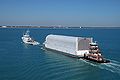
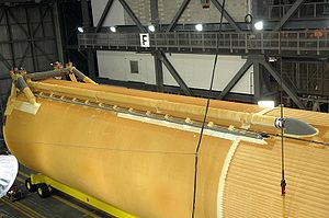
), New Orleans, Louisiana. The tank is manufactured at the Michoud Assembly Facility
Michoud Assembly Facility
The Michoud Assembly Facility is an 832-acre site owned by NASA and located in New Orleans East, a large district within the city of New Orleans, Louisiana, United States. Organizationally, it is part of NASA's Marshall Space Flight Center...
, New Orleans, and is transported to Kennedy Space Center
Kennedy Space Center
The John F. Kennedy Space Center is the NASA installation that has been the launch site for every United States human space flight since 1968. Although such flights are currently on hiatus, KSC continues to manage and operate unmanned rocket launch facilities for America's civilian space program...
by barge
Barge
A barge is a flat-bottomed boat, built mainly for river and canal transport of heavy goods. Some barges are not self-propelled and need to be towed by tugboats or pushed by towboats...
.
Components
The ET has three primary structures: an LOX tank, an intertank, and an LH2 tank. Both tanks are constructed of aluminium alloy skins with support or stability frames as required. The intertank aluminium structure utilizes skin stringers with stabilizing frames. The primary aluminium materials used for all three structures are 2195 and 2090 alloys. AL 2195 is an Al-Li alloy designed by Lockheed Martin and Reynolds for storage of cryogenics. Al 2090 is a commercially available Al-Li alloy.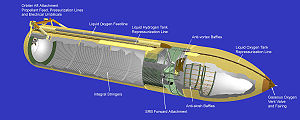
Liquid oxygen tank
The LOX tank is located at the top of the ET and has an ogiveOgive
An ogive is the roundly tapered end of a two-dimensional or three-dimensional object.-Applied physical science and engineering:In ballistics or aerodynamics, an ogive is a pointed, curved surface mainly used to form the approximately streamlined nose of a bullet or other projectile.The traditional...
shape to reduce aerodynamic drag and aerothermodynamic heating. The ogive nose section is capped by a flat removable cover plate and a nose cone
Nose cone
The term nose cone is used to refer to the forwardmost section of a rocket, guided missile or aircraft. The cone is shaped to offer minimum aerodynamic resistance...
. The nose cone consists of a removable conical assembly that serves as an aerodynamic fairing for the propulsion and electrical system components. The forward most element of the nose cone functions as a cast aluminium lightning rod. The LOX tank volume is 19744 cu ft (559.1 m³) at 22 psig (250 kPa absolute) and -297 °F (cryogenic).
The tank feeds into a 17 in (431.8 mm) diameter feed line that conveys the liquid oxygen through the intertank, then outside the ET to the aft right-hand ET/orbiter disconnect umbilical. The 17 in (431.8 mm) diameter feed line permits liquid oxygen to flow at approximately 2,787 lb/s (1264 kg/s) with the SSMEs operating at 104% or permits a maximum flow of 17,592 gal/min (1.1099 m³/s).
All loads except aerodynamic loads are transferred from the LOX tank at a bolted, flange-joint interface with the intertank.
The LOX tank also includes an internal slosh baffle and a vortex baffle to dampen fluid slosh. The vortex baffle is mounted over the LOX feed outlet to reduce fluid swirl resulting from slosh and to prevent entrapment of gases in the delivered LOX.
Intertank
The intertank is the ET structural connection which joins both the LOX and LH2 tanks. Its primary functions are to receive and distribute all thrust loads from the SRBs and transfer loads between the tanks.The two SRB forward attach fittings are located 180° apart on the intertank structure. A beam is extended across the intertank structure and is mechanically fastened to the attach fittings. When the SRBs are firing, the beam will flex due to high stress loads. These loads will be transferred to the fittings.
Adjoining the SRB attach fittings is a major ring frame. The loads are transferred from the fittings to the major ring frame which then distributes the tangential loads to the intertank skin. Two panels of the intertank skin, called the thrust panels, distribute the concentrated axial SRB thrust loads to the LOX and LH2 tanks and to adjacent intertank skin panels. These adjacent panels are made up of six stringer-stiffened panels.
The intertank also functions as a protective compartment for housing the operational instrumentation.
Liquid hydrogen tank
The forward and aft domes have the same modified ellipsoidal shape. For the forward dome, mounting provisions are incorporated for the LH2 vent valve, the LH2 pressurization line fitting, and the electrical feed-through fitting. The aft dome has a manhole fitting for access to the LH2 feedline screen and a support fitting for the LH2 feedline.
The LH2 tank also has a vortex baffle to reduce swirl resulting from slosh and to prevent entrapment of gases in the delivered LH2. The baffle is located at the siphon outlet just above the aft dome of the LH2 tank. This outlet transmits the liquid hydrogen from the tank through a 17 inches (431.8 mm) line to the left aft umbilical. The liquid hydrogen feed line flow rate is 465 lb/s (211 kg/s) with the SSMEs at 104% or a maximum flow of 47,365 US gal/min (2.988 m³/s).
Thermal protection system
Foam
-Definition:A foam is a substance that is formed by trapping gas in a liquid or solid in a divided form, i.e. by forming gas regions inside liquid regions, leading to different kinds of dispersed media...
insulation
Thermal insulation
Thermal insulation is the reduction of the effects of the various processes of heat transfer between objects in thermal contact or in range of radiative influence. Heat transfer is the transfer of thermal energy between objects of differing temperature...
(SOFI), plus preformed foam pieces and premolded ablator materials. The system also includes the use of phenolic thermal
Thermal
A thermal column is a column of rising air in the lower altitudes of the Earth's atmosphere. Thermals are created by the uneven heating of the Earth's surface from solar radiation, and are an example of convection. The sun warms the ground, which in turn warms the air directly above it...
insulators to preclude air liquefaction. Thermal isolators are required for liquid hydrogen tank attachments to preclude the liquefaction of air on exposed metal, and to reduce heat flow into the liquid hydrogen. While the warmer liquid oxygen results in fewer thermal requirements, the aluminum of the liquid oxygen tank forward areas require protection from aeroheating
Aerodynamic heating
Aerodynamic heating is the heating of a solid body produced by the passage of fluid over a body such as a meteor, missile, or airplane. It is a form of forced convection in that the flow field is created by forces beyond those associated with the thermal processes...
. Meanwhile insulation on the aft surfaces prevents liquified air from pooling in the intertank. The middle cylinder of the oxygen tank, and the propellant lines, could withstand the expected depths of frost accumulation condensed from humidity, but the orbiter could not take the damage from ice breaking free. The thermal protection system weighs 4823 lb (2,187.7 kg).
Development of the ETs thermal protection system has been problematic. Anomalies in foam application were so frequent that they were treated as variances, not safety incidents. NASA has had difficulty preventing fragments of foam from detaching during flight for the entire history of the program:
- STS-1STS-1STS-1 was the first orbital flight of NASA's Space Shuttle program. Space Shuttle Columbia launched on 12 April 1981, and returned to Earth on 14 April, having orbited the Earth 37 times during the 54.5-hour mission. It was the first American manned space flight since the Apollo-Soyuz Test Project...
, 1981: Crew reports white material streaming past windows during orbiter-external-tank flight. Crew estimated sizes from 1/4-inch to fist-sized. Post-landing report describes probable foam loss of unknown location, and 300 tiles needing outright replacement due to various causes.
- STS-4STS-4STS-4 was a NASA Space Shuttle mission, using the Space Shuttle Columbia. The mission launched on 27 June 1982 and landed a week later on 4 July. STS-4 was the fourth shuttle mission overall, and was also the fourth mission for the Columbia.-Crew:...
, 1982: PAL ramp loss; 40 tiles require outright replacement.
- STS-5STS-5STS-5 was a NASA Space Shuttle mission, the fifth shuttle mission overall and the fifth flight of the Space Shuttle Columbia. It was the first shuttle mission to deploy communications satellites into orbit...
, 1982: Continued high rate of tile loss.
- STS-7STS-7STS-7 was a NASA Space Shuttle mission, during which Space Shuttle Challenger deployed several satellites into orbit. The shuttle launched from Kennedy Space Center on 18 June 1983, and landed at Edwards Air Force Base on 24 June. STS-7 was the seventh shuttle mission, and was Challengers second...
, 1983: 50 by Bipod ramp loss photographed, dozens of spot losses.
- STS-27STS-27STS-27 was a NASA Space Shuttle mission, the 27th shuttle mission overall and the third flight of Space Shuttle Atlantis. Launching on 2 December 1988 on a four-day mission, it was the second shuttle flight after the Space Shuttle Challenger disaster of 1986. STS-27 carried a classified payload for...
, 1988: One large loss of uncertain origin, causing one total tile loss. Hundreds of small losses.
- STS-32STS-32STS-32 was the 33rd mission of NASA's Space Shuttle program, and the 9th launch of Space Shuttle Columbia. Launching on 9 January 1990, it marked the first time since STS-61-C that Pad A at Kennedy Space Center's Complex 39 was used for a launch; it also marked the first use of Mobile Launcher...
, 1990: Bipod ramp loss photographed; five spot losses up to 70 cm in diameter, plus tile damages.
- STS-50STS-50-Backup crew:-Mission parameters:*Mass:**Orbiter landing with payload: **Payload: *Perigee: *Apogee: *Inclination: 28.5°*Period: 90.6 min- Mission highlights:...
, 1992: Bipod ramp loss. 20×10×1 cm tile damage.
- STS-52STS-52-Mission parameters:*Mass:**Orbiter landing with payload: **Payload: *Perigee: *Apogee: *Inclination: 28.5°*Period: 90.6 min-Mission highlights:...
, 1992: Portion of bipod ramp, jackpad lost. 290 total tile marks, 16 greater than an inch.
- STS-62STS-62STS-62 was a Space Shuttle program mission flown aboard . The primary payloads were the USMP-02 microgravity experiments package and the OAST-2 engineering and technology payload, both in the orbiter's cargo bay. The two-week mission also featured a number of biomedical experiments focusing on the...
, 1994: Portion of bipod ramp lost.
In 1995, chlorofluorocarbon-11
Trichlorofluoromethane
Trichlorofluoromethane, also called freon-11, CFC-11, or R-11, is a chlorofluorocarbon. It is a colorless, nearly odorless liquid that boils at about room temperature.- Uses :It was the first widely used refrigerant...
(CFC-11) began to be withdrawn from large-area, machine-sprayed foams in compliance with an Environmental Protection Agency
United States Environmental Protection Agency
The U.S. Environmental Protection Agency is an agency of the federal government of the United States charged with protecting human health and the environment, by writing and enforcing regulations based on laws passed by Congress...
ban on CFCs under section 610 of the Clean Air Act
Clean Air Act
A Clean Air Act is one of a number of pieces of legislation relating to the reduction of airborne contaminants, smog and air pollution in general. The use by governments to enforce clean air standards has contributed to an improvement in human health and longer life spans...
. In its place, a hydrochlorofluorocarbon known as HCFC-141b
1,1-Dichloro-1-fluoroethane
1,1-Dichloro-1-fluoroethane is a haloalkane with the formula . It is one of the three isomers of dichlorofluoroethane.- Use :1,1-Dichloro-1-fluoroethane is mainly used as a refrigerant under the names R-141b or HCFC-141b.- Physico-chemical properties :...
was certified for use and phased into the shuttle program. Remaining foams, particularly detail pieces sprayed by hand, continue to use CFC-11 to this day. These areas include the problematic bipod and PAL ramps, as well as some fittings and interfaces. For the bipod ramp in particular, "the process of applying foam to that part of the tank had not changed since 1993." The "new" foam containing HCFC 141b was first used on the aft dome portion of ET-82 during the flight of STS-79
STS-79
STS-79 was a Space Shuttle Atlantis mission to the Mir space station. It was the first shuttle mission to dock with Mir once it was fully assembled.-Crew:-Mission parameters:*Mass:**Spacehab-Double Module **Orbiter Docking System...
in 1996. Use of HCFC 141b was expanded to the ETs area, or larger portions of the tank, starting with ET-88, which flew on STS-86
STS-86
STS-86 was a Space Shuttle Atlantis mission to the Mir space station. This was the last Atlantis mission before it was taken out of service temporarily for maintenance and upgrades, including the glass cockpit.-Crew:-Crew notes:...
in 1997.
During the lift-off of STS-107
STS-107
-Mission parameters:*Mass:**Orbiter Liftoff: **Orbiter Landing: **Payload: *Perigee: *Apogee: *Inclination: 39.0°*Period: 90.1 min- Insignia :...
, a piece of foam insulation detached from one of the tank's bipod ramps and struck the leading edge of Space Shuttle Columbia
Space Shuttle Columbia
Space Shuttle Columbia was the first spaceworthy Space Shuttle in NASA's orbital fleet. First launched on the STS-1 mission, the first of the Space Shuttle program, it completed 27 missions before being destroyed during re-entry on February 1, 2003 near the end of its 28th, STS-107. All seven crew...
's wing at a few hundred miles per hour. The impact is believed to have damaged one comparatively large reinforced carbon-carbon panel on the leading edge of the left wing, believed to be about the size of a basketball which then allowed super-heated gas to enter the wing superstructure several days later during re-entry. This resulted in the destruction of Columbia
Space Shuttle Columbia disaster
The Space Shuttle Columbia disaster occurred on February 1, 2003, when shortly before it was scheduled to conclude its 28th mission, STS-107, the Space Shuttle Columbia disintegrated over Texas and Louisiana during re-entry into the Earth's atmosphere, resulting in the death of all seven crew members...
and the loss of its crew. The report determined that the external fuel tank, ET-93, "had been constructed with BX-250", a closeout foam whose blowing agent was CFC-11 and not the newer HCFC 141b.
In 2005, the problem of foam shed had not been fully cured; on STS-114
STS-114
-Original crew:This mission was to carry the Expedition 7 crew to the ISS and bring home the Expedition 6 crew. The original crew was to be:-Mission highlights:...
, additional cameras mounted on the tank recorded a piece of foam separated from one of its Protuberance Air Load (PAL) ramps, which are designed to prevent unsteady air flow underneath the tank’s cable trays and pressurization lines during ascent. The PAL ramps consist of manually sprayed layers of foam, and are more likely to become a source of debris. That piece of foam did not impact the orbiter.
Reports published concurrent with the STS-114
STS-114
-Original crew:This mission was to carry the Expedition 7 crew to the ISS and bring home the Expedition 6 crew. The original crew was to be:-Mission highlights:...
mission suggest that excessive handling of the ET during modification and upgrade may have contributed to the foam loss on Discoverys Return to Flight mission. However, three shuttle missions (STS-121
STS-121
STS-121 was a space shuttle mission to the International Space Station flown by Space Shuttle Discovery. The main purposes of the mission were to test new safety and repair techniques introduced following the Columbia disaster of February 2003 as well as to deliver supplies, equipment and...
, STS-115
STS-115
Note:The P3/P4 Truss segment and batteries were so heavy that the crew count was reduced from seven to six.-Crew notes:...
, and STS-116
STS-116
-Crew notes:Originally this mission was to carry the Expedition 8 crew to the ISS. The original crew was to be:-Mission highlights:* The STS-116 mission delivered and attached the International Space Station's third port truss segment, the P5 truss....
) have since been conducted, all with "acceptable" levels of foam loss. However on STS-118
STS-118
- Crew notes :Astronaut Clayton Anderson originally was slated to be launched to the ISS on this mission, but was moved to STS-117. His replacement was Alvin Drew....
a piece of foam (and/or ice) about 10 cm in diameter separated from a feedline attachment bracket on the tank, ricocheted off one of the aft struts and struck the underside of the wing, damaging two tiles. The damage was not considered dangerous.
Hardware
.jpg)
Vents and relief valves
Each propellant tank has a ventVent
Vent may refer to:*Vent , a slit up the back of a jacket or coat*Vent , a valve fitted to the top of a submarine's ballast tanks*Vent , a 2001 album by Caliban...
and relief valve
Relief valve
The relief valve is a type of valve used to control or limit the pressure in a system or vessel which can build up by a process upset, instrument or equipment failure, or fire....
at its forward end. This dual-function valve can be opened by ground support equipment for the vent function during prelaunch and can open during flight when the ullage
Ullage
Ullage or Headspace refers to the unfilled space in a container, particularly with a liquid.-Etymology:The word comes ultimately from the Latin oculus, “eye”, which was used in a figurative sense by the Romans for the bung hole of a barrel...
(empty space) pressure of the liquid hydrogen tank reaches 38 psig (262 kPa) or the ullage pressure of the liquid oxygen tank reaches 25 psig (172 kPa).
The liquid oxygen tank contains a separate, pyrotechnically operated, propulsive tumble vent valve at its forward end. At separation, the liquid oxygen tumble vent valve is opened, providing impulse to assist in the separation maneuver and more positive control of the entry aerodynamics of the ET.
Each of the two aft external tank umbilical plates mate with a corresponding plate on the orbiter. The plates help maintain alignment among the umbilicals. Physical strength at the umbilical plates is provided by bolting corresponding umbilical plates together. When the orbiter GPCs command external tank separation, the bolts are severed by pyrotechnic devices.
The ET has five propellant umbilical valves that interface with orbiter umbilicals: two for the liquid oxygen tank and three for the liquid hydrogen tank. One of the liquid oxygen tank umbilical valves is for liquid oxygen, the other for gaseous oxygen. The liquid hydrogen tank umbilical has two valves for liquid and one for gas. The intermediate-diameter liquid hydrogen umbilical is a recirculation umbilical used only during the liquid hydrogen chill-down sequence during prelaunch.
As the ET is filled, excess gaseous hydrogen is vented through umbilical connections over a large diameter pipe on an arm extended from the fixed service structure. The connection for this pipe between the ET and service structure is made at the ground umbilical carrier plate (GUCP). Sensors are also installed at the GUCP to measure Hydrogen levels. Countdowns of STS-80
STS-80
-Mission parameters:* Mass: payload* Perigee: * Apogee: * Inclination: 28.5°* Period: 91.5 min-Mission highlights:* The mission deployed two satellites and successfully recovered them after they had performed their tasks....
, STS-119
STS-119
-Crew notes:This mission was originally scheduled to bring the Expedition 9 crew to the ISS. This crew would have consisted of:-Mission parameters:* Mass:* Orbiter liftoff: * Orbiter landing: * Perigee: * Apogee:...
, STS-127
STS-127
STS-127 was a NASA Space Shuttle mission to the International Space Station . It was the twenty-third flight of . The primary purpose of the STS-127 mission was to deliver and install the final two components of the Japanese Experiment Module: the Exposed Facility , and the Exposed Section of the...
and STS-133
STS-133
STS-133 was the 133rd mission in NASA's Space Shuttle program; during the mission, Space Shuttle Discovery docked with the International Space Station. It was Discoverys 39th and final mission. The mission launched on 24 February 2011, and landed on 9 March 2011...
have been halted and resulted in several week delays in the later cases due to hydrogen leaks at this connection. This requires complete draining of the tanks and removal of all hydrogen via helium gas purge, a 20 hour process, before technicians can inspect and repair problems.
A cap mounted to the swing-arm on the fixed service structure covers the oxygen tank vent on top of the ET during the countdown and is retracted about two minutes before lift- off. The cap siphons off oxygen vapor that threatens to form large ice on the ET, thus protecting the orbiter's thermal protection system during launch.
Sensors
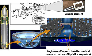
The locations of the liquid oxygen sensors allow the maximum amount of oxidizer to be consumed in the engines, while allowing sufficient time to shut down the engines before the oxidizer pumps cavitate
Cavitation
Cavitation is the formation and then immediate implosion of cavities in a liquidi.e. small liquid-free zones that are the consequence of forces acting upon the liquid...
(run dry). In addition, 1100 lb (499 kg) of liquid hydrogen are loaded over and above that required by the 6-1 oxidizer / fuel engine mixture ratio. This assures that cutoff from the depletion sensors is fuel-rich; oxidizer-rich engine shutdowns can cause burning and severe erosion of engine components, potentially leading to loss of the vehicle and crew.
Unexplained, erroneous readings from fuel depletion sensors have delayed several shuttle launch attempts, most notably STS-122
STS-122
STS-122 was a NASA Space Shuttle mission to the International Space Station , flown by the Space Shuttle Atlantis. STS-122 marked the 24th shuttle mission to the ISS, and the 121st space shuttle flight since STS-1....
. On 2007-12-18 a tanking test determined the cause of the errors to be a fault in a wiring connector, rather than a failure of the sensors themselves.
Four pressure transducers located at the top of the liquid oxygen and liquid hydrogen tanks monitor the ullage pressures.
The ET also has two electrical umbilicals that carry electrical power from the orbiter to the tank and the two SRBs and provide information from the SRBs and ET to the orbiter.
The ET has external cameras mounted in the brackets attached to the shuttle along with transmitters that can continue to send video data long after the shuttle and the ET have separated.
Range safety system
Earlier tanks incorporated a range safety system to disperse tank propellants if necessary. It included a batteryBattery (electricity)
An electrical battery is one or more electrochemical cells that convert stored chemical energy into electrical energy. Since the invention of the first battery in 1800 by Alessandro Volta and especially since the technically improved Daniell cell in 1836, batteries have become a common power...
power source, a receiver/decoder, antennas and ordnance
Explosive material
An explosive material, also called an explosive, is a reactive substance that contains a great amount of potential energy that can produce an explosion if released suddenly, usually accompanied by the production of light, heat, sound, and pressure...
. Starting with STS-79
STS-79
STS-79 was a Space Shuttle Atlantis mission to the Mir space station. It was the first shuttle mission to dock with Mir once it was fully assembled.-Crew:-Mission parameters:*Mass:**Spacehab-Double Module **Orbiter Docking System...
, this system was no longer used. The assembly was completely removed by the time STS-88
STS-88
-Mission parameters:*Weight*Liftoff: *Landing: *Perigee: *Apogee: *Orbital Period: 92.4min-Launch attempts:-Mission highlights:Node 1, named Unity, was the first space station hardware delivered by the space shuttle. It has two Pressurized Mating Adapters , one attached to either end...
flew and has not been present on any tank since then. Consequently, it is no longer possible to destroy the vehicle during second stage ascent.
Variants
A cargo carrier addition was studied in 1984. This would consist of a cargo space mounted to the aft hydrogen dome, for cargoes greater than the payload bay diameter of 15 feet (4.6 m). It never flew.Before the Challenger accident, proposed west coast launches by the military into polar orbit
Polar orbit
A polar orbit is an orbit in which a satellite passes above or nearly above both poles of the body being orbited on each revolution. It therefore has an inclination of 90 degrees to the equator...
s suffered a disadvantage in lifting capacity compared to low-inclination orbits. A booster module, derived from a Titan II first stage, was proposed. In addition to increasing capacity, the presence of tankage and rocket exhaust would have relieved heating on the aft hydrogen dome. This also failed to fly.
Future use
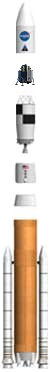
Project Constellation
Constellation Program is a human spaceflight program within NASA, the space agency of the United States. The stated goals of the program were to gain significant experience in operating away from Earth's environment, develop technologies needed for opening the space frontier, and conduct...
, which features the Apollo
Project Apollo
The Apollo program was the spaceflight effort carried out by the United States' National Aeronautics and Space Administration , that landed the first humans on Earth's Moon. Conceived during the Presidency of Dwight D. Eisenhower, Apollo began in earnest after President John F...
-derived Orion spacecraft, will also feature the debut of two Shuttle-derived launch vehicles, the man-rated
Human-rating certification
Human-rated or man-rated are terms used to describe the certification of a spacecraft, launch vehicleor airplaneas worthy of transporting humans. NASA and the U.S. GAO now uses "Human-rating" when describing requirements for these systems...
Ares I
Ares I
Ares I was the crew launch vehicle that was being developed by NASA as part of the Constellation Program. The name "Ares" refers to the Greek deity Ares, who is identified with the Roman god Mars...
crew-launch vehicle and the heavy-lift Ares V
Ares V
The Ares V was the planned cargo launch component of the Constellation program, which was to have replaced the Space Shuttle after its retirement in 2011. Ares V was also planned to carry supplies for a human presence on Mars...
cargo-launch vehicle.
While both the Ares I and Ares V will utilize a modified five-segment Solid Rocket Booster for its first stage, the current ET will serve as a baseline technology for the first stage of the Ares V and the second stage of the Ares I; as a comparison, the Ares I second stage will hold approximately 26000 US gal (98,420.7 l) of LOX, versus the ET holding 146000 US gal (552,670.2 l), more than 5 times that amount.
The Ares V first stage, which will be fitted with five RS-68
RS-68 (rocket engine)
The Pratt & Whitney Rocketdyne RS-68 is a liquid-fuel rocket engine that burns liquid hydrogen with liquid oxygen . It is the largest hydrogen-fueled engine in the world. Development of the engine started in the 1990s with the goal of producing a simpler, less-costly, heavy-lift engine for the...
rocket engines (the same engine used on the Delta IV rocket
Delta IV rocket
Delta IV is an active expendable launch system in the Delta rocket family. Delta IV uses rockets designed by Boeing's Integrated Defense Systems division and built in the United Launch Alliance facility in Decatur, Alabama. Final assembly is completed at the launch site by ULA...
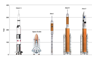
), will be 33 feet (10 m) in diameter, as wide as the S-IC
S-IC
The S-IC was the first stage of the Saturn V rocket. The S-IC first stage was built by The Boeing Company. Like the first stages of most rockets, most of its mass of over two thousand metric tonnes at launch was propellant, in this case RP-1 rocket fuel and liquid oxygen oxidizer...
and S-II
S-II
The S-II was the second stage of the Saturn V rocket. It was built by North American Aviation. Using liquid hydrogen and liquid oxygen it had five J-2 engines in a cross pattern...
stages on the Saturn V
Saturn V
The Saturn V was an American human-rated expendable rocket used by NASA's Apollo and Skylab programs from 1967 until 1973. A multistage liquid-fueled launch vehicle, NASA launched 13 Saturn Vs from the Kennedy Space Center, Florida with no loss of crew or payload...
rocket. It will utilize the same internal ET configuration (separate LH2 and LOX tanks separated with an intertank structure), but will be configured to directly accept LH2 and LOX fill and drain, along with LOX venting on a retractable arm like that used on the Shuttle for LH2 (as the "beanie cap" would be useless due to the in-line design of the three-stage vehicle).
S-IVB
The S-IVB was built by the Douglas Aircraft Company and served as the third stage on the Saturn V and second stage on the Saturn IB. It had one J-2 engine...
stages of the Saturn V rocket. Unlike the Ares V, which will use the same fill/drain/vent configuration used on the Shuttle, the Ares I system will utilize a traditional fill/drain/vent system used on the Saturn IB and Saturn V rockets, but with quick-retracting arms due to the "leap frog" speed the Ares I will expect upon SRB ignition.
As originally envisioned, both the Ares I and Ares V would have used a modified "throw away" version of the SSME
Space Shuttle main engine
The RS-25, otherwise known as the Space Shuttle Main Engine , is a reusable liquid-fuel rocket engine built by Pratt & Whitney Rocketdyne for the Space Shuttle, running on liquid hydrogen and oxygen. Each Space Shuttle was propelled by three SSMEs mated to one powerhead...
, but in due course, because of the need to keep R&D costs down and to maintain a schedule set by NASA Administration Michael D. Griffin
Michael D. Griffin
Michael Douglas Griffin is an American physicist and aerospace engineer. From April 13, 2005 to January 20, 2009 he served as Administrator of NASA, the space agency of the United States...
to launch the Ares and Orion by 2011, NASA decided to switch to the RS-68 engine for the Ares V and to an uprated J-2
J-2 (rocket engine)
Rocketdyne's J-2 rocket engine was a major component of the Saturn V rocket used in the Apollo program to send men to the Moon. Five J-2 engines were used on the S-II second stage, and one J-2 was used on the S-IVB third stage. The S-IVB was also used as the second stage of the smaller Saturn IB...
engine for the Ares I. Because of the switch to the RS-68, the Ares V was widened from 28.6 to 33 ft (8.7 to 10.1 m) to accommodate the extra propellants, while the Ares I was reconfigured to incorporate a fifth solid-rocket segment as the J-2X, as the rocket engine is known, has less thrust than the SSME. Because of the trade-off, NASA would save an estimated USD $35 million by using simplified, higher thrust RS-68 engines (reconfigured to fire and perform like the SSME), while at the same time, eliminate the costly tests needed for an air-startable SSME for the Ares I (as the J-2X and its predecessor were designed to be started in both mid-air and in a near vacuum).
The DIRECT
DIRECT
DIRECT is a proposed alternative heavy lift launch vehicle architecture supporting NASA's Vision for Space Exploration, which would replace the space agency's planned Ares I and Ares V rockets...
project, a proposed alternative shuttle-derived vehicle, uses a modified, standard diameter, external tank with three SSMEs, with two standard SRBM, as a Crew Launch Vehicle. The same vehicle, with one extra SSME, and an EDS upper stage, serves as the Cargo Launch Vehicle. It is purported to save $16 billion, eliminate NASA job losses, and reduce the post-shuttle, manned spaceflight gap from five plus years to two or less.
Unflown hardware
ET-94 (older version LWT), currently in storage at Michoud Assembly FacilityMichoud Assembly Facility
The Michoud Assembly Facility is an 832-acre site owned by NASA and located in New Orleans East, a large district within the city of New Orleans, Louisiana, United States. Organizationally, it is part of NASA's Marshall Space Flight Center...
, will be used for development and tests of in-line Shuttle-Derived Launch Vehicle
Shuttle-Derived Launch Vehicle
Shuttle-Derived Launch Vehicle, or simply Shuttle-Derived Vehicle , is a term describing one of a wide array of concepts that have been developed for creating space launch vehicles from the components, technology and/or infrastructure of the Space Shuttle program. SDVs have also been part of...
, the Space Launch System
Space Launch System
The Space Launch System, or SLS, is a Space Shuttle-derived heavy launch vehicle being designed by NASA, following the cancellation of the Constellation Program, to replace the retired Space Shuttle. The NASA Authorization Act of 2010 envisions the transformation of the Ares I and Ares V vehicle...
.
Three other external tanks were in preparation, when the manufacturing stopped. ET-139 is at advanced stage of manufacturing; ET-140 and ET-141 are in early stages of manufacturing.
Further reading
- "External Tank Thermal Protection System" NASA Facts "Return to Flight Focus Area," National Aeronautics and Space Administration, Marshall Space Flight Center, Huntsville, Alabama (Pub 8-40392, FS2005-4-10-MSFC, April 2005)
- National Aeronautics and Space Administration. Booster Systems Briefs. Basic, Rev F, PCN 1. April 27, 2005.
- National Aeronautics and Space Administration. Shuttle Systems Design Criteria. Volume I: Shuttle Performance Assessment Databook. NSTS 08209, Volume I, Revision B. March 16, 1999.
External links
- Space Shuttle Propulsion and External Tank Photo Gallery
- STS-115 Launch as seen from ET Camera Video
- Columbia Accident Investigation Board Report Vol. 1, Chp. 3, "Accident Analysis" August 2003
- STS-125 View of the External Tank Jettisoned and in decaying orbit as viewed from the Shuttle Atlantis Video
- Spherical panorama of the bottom of ET-122 in its scaffolding at Michoud Assembly Facility
- Spherical panorama of the top of ET-122 in its scaffolding at Michoud Assembly Facility
- Spherical panorama of the top of ET-138 in its scaffolding at Michoud Assembly Facility. This is the last tank scheduled to fly.
- Spherical panorama along the centerline of the bottom of ET-138 near the feedlines in its scaffolding at Michoud Assembly Facility. This is the last tank scheduled to fly.