
Butterworth filter
Encyclopedia
The Butterworth filter is a type of signal processing filter
designed to have as flat a frequency response
as possible in the passband
so that it is also termed a maximally flat magnitude filter. It was first described in 1930 by the British engineer
Stephen Butterworth
in his paper entitled "On the Theory of Filter Amplifiers".
required an amount of designer experience due to limitations of the theory then in use. The filter was not in common use for over 30 years after its publication. Butterworth stated that:
Such an ideal filter cannot be achieved but Butterworth showed that successively closer approximations were obtained with increasing numbers of filter elements of the right values. At the time, filters generated substantial ripple in the passband, and the choice of component values was highly interactive. Butterworth showed that a low pass filter could be designed whose cutoff frequency was normalized to 1 radian per second and whose frequency response (gain
) was

where ω is the angular frequency
in radians per second and n is the number of reactive elements (poles) in the filter. If ω = 1, the amplitude response of this type of filter in the passband is 1/ ≈ 0.707, which is half power or −3 dB
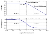
. Butterworth only dealt with filters with an even number of poles in his paper. He may have been unaware that such filters could be designed with an odd number of poles. He built his higher order filters from 2-pole filters separated by vacuum tube amplifiers. His plot of the frequency response of 2, 4, 6, 8, and 10 pole filters is shown as A, B, C, D, and E in his original graph.
Butterworth solved the equations for two- and four-pole filters, showing how the latter could be cascaded when separated by vacuum tube
amplifier
s and so enabling the construction of higher-order filters despite inductor
losses. In 1930 low-loss core materials such as molypermalloy
had not been discovered and air-cored audio inductors were rather lossy. Butterworth discovered that it was possible to adjust the component values of the filter to compensate for the winding resistance of the inductors.
He used coil forms of 1.25″ diameter and 3″ length with plug in terminals. Associated capacitors and resistors were contained inside the wound coil form. The coil formed part of the plate load resistor. Two poles were used per vacuum tube and RC coupling was used to the grid of the following tube.
Butterworth also showed that his basic low-pass filter could be modified to give low-pass
, high-pass
, band-pass
and band-stop
functionality.
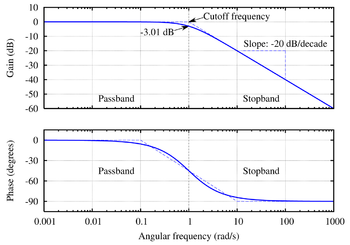 The frequency response of the Butterworth filter is maximally flat (has no ripples) in the passband and rolls off towards zero in the stopband.
When viewed on a logarithmic Bode plot
the response slopes off linearly towards negative infinity. A first-order filter's response rolls off at −6 dB
per octave
(−20 dB per decade
) (all first-order lowpass filters have the same normalized frequency response). A second-order filter decreases at −12 dB per octave, a third-order at −18 dB and so on. Butterworth filters have a monotonically changing magnitude function with ω, unlike other filter types that have non-monotonic ripple in the passband and/or the stopband.
Compared with a Chebyshev
Type I/Type II filter or an elliptic filter
, the Butterworth filter has a slower roll-off
, and thus will require a higher order to implement a particular stopband
specification, but Butterworth filters have a more linear phase response in the pass-band than Chebyshev Type I/Type II and elliptic filters can achieve.
 A simple example of a Butterworth filter is the third-order low-pass design shown in the figure on the right, with C2 = 4/3 F, R4 = 1 Ω, L1 = 3/2 H, and L3 = 1/2 H. Taking the impedance
of the capacitors C to be 1/Cs and the impedance of the inductors L to be Ls, where is the complex frequency, the circuit equations yield the transfer function
for this device:
The magnitude of the frequency response (gain) G(ω) is given by
and the phase
is given by

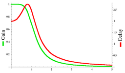 The group delay
is defined as the derivative of the phase with respect to angular frequency and is a measure of the distortion in the signal introduced by phase differences for different frequencies. The gain and the delay for this filter are plotted in the graph on the left. It can be seen that there are no ripples in the gain curve in either the passband or the stop band.
The log of the absolute value of the transfer function H(s) is plotted in complex frequency space in the second graph on the right. The function is defined by the three poles in the left half of the complex frequency plane..svg.png) These are arranged on a circle of radius unity, symmetrical about the real s axis. The gain function will have three more poles on the right half plane to complete the circle.
These are arranged on a circle of radius unity, symmetrical about the real s axis. The gain function will have three more poles on the right half plane to complete the circle.
By replacing each inductor with a capacitor and each capacitor with an inductor, a high-pass
Butterworth filter is obtained.
A band-pass
Butterworth filter is obtained by placing a capacitor in series with each inductor and an inductor in parallel with each capacitor to form resonant circuits. The value of each new component must be selected to resonate with the old component at the frequency of interest.
A band-stop
Butterworth filter is obtained by placing a capacitor in parallel with each inductor and an inductor in series with each capacitor to form resonant circuits. The value of each new component must be selected to resonate with the old component at the frequency to be rejected.
 Like all filters, the typical prototype
is the low-pass filter
, which can be modified into a high-pass filter, or placed in series with others to form band-pass and band-stop filters, and higher order versions of these.
The gain of an n-order Butterworth low pass filter is given in terms of the transfer function
H(s) as
where
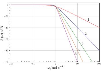
It can be seen that as n approaches infinity, the gain becomes a rectangle function and frequencies below ωc will be passed with gain , while frequencies above ωc will be suppressed. For smaller values of n, the cutoff will be less sharp.
We wish to determine the transfer function H(s) where (from Laplace transform). Since H(s)H(-s) evaluated at s = jω is simply equal to |H(jω)|2, it follows that

The poles of this expression occur on a circle of radius ωc at equally spaced points. The transfer function itself will be specified by just the poles in the negative real half-plane of s. The k-th pole is specified by

and hence;

The transfer function may be written in terms of these poles as

The denominator is a Butterworth polynomial in s.
 and
and  . The polynomials are normalized by setting
  . The normalized Butterworth polynomials then have the general form
 for n even
 for n odd
To four decimal places, they are
The normalized Butterworth polynomials can be used to determine the transfer function for any low-pass filter
cut-off frequency , as follows
 , where
Transformation to other bandforms are also possible, see prototype filter
.
 and
and  , the derivative of the gain with respect to frequency can be shown to be

which is monotonically decreasing for all since the gain G is always positive. The gain function of the Butterworth filter therefore has no ripple. Furthermore, the series expansion of the gain is given by

In other words all derivatives of the gain up to but not including the 2n-th derivative are zero, resulting in "maximal flatness". If the requirement to be monotonic is limited to the passband only and ripples are allowed in the stopband, then it is possible to design a filter of the same order, such as the inverse Chebyshev filter, that is flatter in the passband than the "maximally flat" Butterworth.
 , the slope of the log of the gain for large ω is

In decibel
s, the high-frequency roll-off
is therefore 20n dB/decade, or 6n dB/octave (the factor of 20 is used because the power is proportional to the square of the voltage gain; see 20 log rule.)
available to implement a linear analogue filter. The most often used topology for a passive realisation is Cauer topology and the most often used topology for an active realisation is Sallen–Key topology.
 The Cauer topology uses passive components (shunt capacitors and series inductors) to implement a linear analog filter. The Butterworth filter having a given transfer function can be realised using a Cauer 1-form. The kth element is given by;
 ; k = odd
 ; k = even
The filter may start with a series inductor if desired, in which case the are k odd and the
  are k even.
 The Sallen–Key topology uses active and passive components (noninverting buffers, usually op amps, resistors, and capacitors) to implement a linear analog filter. Each Sallen–Key stage implements a conjugate pair of poles; the overall filter is implemented by cascading all stages in series. If there is a real pole (in the case where
  is odd), this must be implemented separately, usually as an RC circuit
, and cascaded with the active stages.
For the second-order Sallen–Key circuit shown to the right the transfer function is given by;

We wish the denominator to be one of the quadratic terms in a Butterworth polynomial. Assuming that , this will mean that;

and;

This leaves two undefined component values that may be chosen at will.
method or the matched Z-transform method
, two different methods to discretize an analog filter design. In the case of all-pole filters such as the Butterworth, the matched Z-transform method is equivalent to the impulse invariance
method. For higher orders, digital filters are sensitive to quantization errors, so they are often calculated as cascaded biquad sections, plus one first-order or third-order section for odd orders.
 The Butterworth filter rolls off more slowly around the cutoff frequency than the Chebyshev filter
or the Elliptic filter
, but without ripple.
Filter (signal processing)
In signal processing, a filter is a device or process that removes from a signal some unwanted component or feature. Filtering is a class of signal processing, the defining feature of filters being the complete or partial suppression of some aspect of the signal...
designed to have as flat a frequency response
Frequency response
Frequency response is the quantitative measure of the output spectrum of a system or device in response to a stimulus, and is used to characterize the dynamics of the system. It is a measure of magnitude and phase of the output as a function of frequency, in comparison to the input...
as possible in the passband
Passband
A passband is the range of frequencies or wavelengths that can pass through a filter without being attenuated.A bandpass filtered signal , is known as a bandpass signal, as opposed to a baseband signal....
so that it is also termed a maximally flat magnitude filter. It was first described in 1930 by the British engineer
Engineer
An engineer is a professional practitioner of engineering, concerned with applying scientific knowledge, mathematics and ingenuity to develop solutions for technical problems. Engineers design materials, structures, machines and systems while considering the limitations imposed by practicality,...
Stephen Butterworth
Stephen Butterworth
Stephen Butterworth was a British physicist who invented the Butterworth filter, a class of electrical circuits that are used to separate different frequencies of electrical signals....
in his paper entitled "On the Theory of Filter Amplifiers".
Original paper
Butterworth had a reputation for solving "impossible" mathematical problems. At the time filter designFilter design
Filter design is the process of designing a filter , often a linear shift-invariant filter, that satisfies a set of requirements, some of which are contradictory...
required an amount of designer experience due to limitations of the theory then in use. The filter was not in common use for over 30 years after its publication. Butterworth stated that:
Such an ideal filter cannot be achieved but Butterworth showed that successively closer approximations were obtained with increasing numbers of filter elements of the right values. At the time, filters generated substantial ripple in the passband, and the choice of component values was highly interactive. Butterworth showed that a low pass filter could be designed whose cutoff frequency was normalized to 1 radian per second and whose frequency response (gain
Gain
In electronics, gain is a measure of the ability of a circuit to increase the power or amplitude of a signal from the input to the output. It is usually defined as the mean ratio of the signal output of a system to the signal input of the same system. It may also be defined on a logarithmic scale,...
) was
where ω is the angular frequency
Angular frequency
In physics, angular frequency ω is a scalar measure of rotation rate. Angular frequency is the magnitude of the vector quantity angular velocity...
in radians per second and n is the number of reactive elements (poles) in the filter. If ω = 1, the amplitude response of this type of filter in the passband is 1/ ≈ 0.707, which is half power or −3 dB
Decibel
The decibel is a logarithmic unit that indicates the ratio of a physical quantity relative to a specified or implied reference level. A ratio in decibels is ten times the logarithm to base 10 of the ratio of two power quantities...
. Butterworth only dealt with filters with an even number of poles in his paper. He may have been unaware that such filters could be designed with an odd number of poles. He built his higher order filters from 2-pole filters separated by vacuum tube amplifiers. His plot of the frequency response of 2, 4, 6, 8, and 10 pole filters is shown as A, B, C, D, and E in his original graph.
Butterworth solved the equations for two- and four-pole filters, showing how the latter could be cascaded when separated by vacuum tube
Vacuum tube
In electronics, a vacuum tube, electron tube , or thermionic valve , reduced to simply "tube" or "valve" in everyday parlance, is a device that relies on the flow of electric current through a vacuum...
amplifier
Amplifier
Generally, an amplifier or simply amp, is a device for increasing the power of a signal.In popular use, the term usually describes an electronic amplifier, in which the input "signal" is usually a voltage or a current. In audio applications, amplifiers drive the loudspeakers used in PA systems to...
s and so enabling the construction of higher-order filters despite inductor
Induction
-General use:* Induction , induction of childbirth* Rite of passage** Introduction of an individual into a body such as the armed forces** Formal introduction of a priest into possession of the position to which she or he has been presented and instituted...
losses. In 1930 low-loss core materials such as molypermalloy
MPP
MPP or M.P.P. may refer to:* 1-methyl-4-phenylpyridine, a toxic metabolite of MPTP causing symptoms of Parkinson's disease* Macro Pre-Processor, a make-like tool forming part of the package utility distributed with OpenAFS...
had not been discovered and air-cored audio inductors were rather lossy. Butterworth discovered that it was possible to adjust the component values of the filter to compensate for the winding resistance of the inductors.
He used coil forms of 1.25″ diameter and 3″ length with plug in terminals. Associated capacitors and resistors were contained inside the wound coil form. The coil formed part of the plate load resistor. Two poles were used per vacuum tube and RC coupling was used to the grid of the following tube.
Butterworth also showed that his basic low-pass filter could be modified to give low-pass
Low-pass filter
A low-pass filter is an electronic filter that passes low-frequency signals but attenuates signals with frequencies higher than the cutoff frequency. The actual amount of attenuation for each frequency varies from filter to filter. It is sometimes called a high-cut filter, or treble cut filter...
, high-pass
High-pass filter
A high-pass filter is a device that passes high frequencies and attenuates frequencies lower than its cutoff frequency. A high-pass filter is usually modeled as a linear time-invariant system...
, band-pass
Band-pass filter
A band-pass filter is a device that passes frequencies within a certain range and rejects frequencies outside that range.Optical band-pass filters are of common usage....
and band-stop
Band-stop filter
In signal processing, a band-stop filter or band-rejection filter is a filter that passes most frequencies unaltered, but attenuates those in a specific range to very low levels. It is the opposite of a band-pass filter...
functionality.
Overview
When viewed on a logarithmic Bode plot
Bode plot
A Bode plot is a graph of the transfer function of a linear, time-invariant system versus frequency, plotted with a log-frequency axis, to show the system's frequency response...
the response slopes off linearly towards negative infinity. A first-order filter's response rolls off at −6 dB
Decibel
The decibel is a logarithmic unit that indicates the ratio of a physical quantity relative to a specified or implied reference level. A ratio in decibels is ten times the logarithm to base 10 of the ratio of two power quantities...
per octave
Octave (electronics)
In electronics, an octave is a doubling or halving of a frequency. The term is derived from the musical octave which similarly describes such frequency ratios, but the prefix octa-, denoting eight, has no significance in physics...
(−20 dB per decade
Decade (log scale)
One decade is a factor of 10 difference between two numbers measured on a logarithmic scale. It is especially useful when referring to frequencies and when describing frequency response of electronic systems, such as audio amplifiers and filters.-Calculations:The factor-of-ten in a decade can be...
) (all first-order lowpass filters have the same normalized frequency response). A second-order filter decreases at −12 dB per octave, a third-order at −18 dB and so on. Butterworth filters have a monotonically changing magnitude function with ω, unlike other filter types that have non-monotonic ripple in the passband and/or the stopband.
Compared with a Chebyshev
Chebyshev filter
Chebyshev filters are analog or digital filters having a steeper roll-off and more passband ripple or stopband ripple than Butterworth filters...
Type I/Type II filter or an elliptic filter
Elliptic filter
An elliptic filter is a signal processing filter with equalized ripple behavior in both the passband and the stopband...
, the Butterworth filter has a slower roll-off
Roll-off
Roll-off is a term commonly used to describe the steepness of a transmission function with frequency, particularly in electrical network analysis, and most especially in connection with filter circuits in the transition between a passband and a stopband...
, and thus will require a higher order to implement a particular stopband
Stopband
A stopband is a band of frequencies, between specified limits, through which a circuit, such as a filter or telephone circuit, does not allow signals to pass, or the attenuation is above the required stopband attenuation level...
specification, but Butterworth filters have a more linear phase response in the pass-band than Chebyshev Type I/Type II and elliptic filters can achieve.
Example
Electrical impedance
Electrical impedance, or simply impedance, is the measure of the opposition that an electrical circuit presents to the passage of a current when a voltage is applied. In quantitative terms, it is the complex ratio of the voltage to the current in an alternating current circuit...
of the capacitors C to be 1/Cs and the impedance of the inductors L to be Ls, where is the complex frequency, the circuit equations yield the transfer function
Transfer function
A transfer function is a mathematical representation, in terms of spatial or temporal frequency, of the relation between the input and output of a linear time-invariant system. With optical imaging devices, for example, it is the Fourier transform of the point spread function i.e...
for this device:
The magnitude of the frequency response (gain) G(ω) is given by
and the phase
Phase (waves)
Phase in waves is the fraction of a wave cycle which has elapsed relative to an arbitrary point.-Formula:The phase of an oscillation or wave refers to a sinusoidal function such as the following:...
is given by
Group delay
Group delay is a measure of the time delay of the amplitude envelopes of the various sinusoidal components of a signal through a device under test, and is a function of frequency for each component...
is defined as the derivative of the phase with respect to angular frequency and is a measure of the distortion in the signal introduced by phase differences for different frequencies. The gain and the delay for this filter are plotted in the graph on the left. It can be seen that there are no ripples in the gain curve in either the passband or the stop band.
The log of the absolute value of the transfer function H(s) is plotted in complex frequency space in the second graph on the right. The function is defined by the three poles in the left half of the complex frequency plane.
By replacing each inductor with a capacitor and each capacitor with an inductor, a high-pass
High-pass filter
A high-pass filter is a device that passes high frequencies and attenuates frequencies lower than its cutoff frequency. A high-pass filter is usually modeled as a linear time-invariant system...
Butterworth filter is obtained.
A band-pass
Band-pass filter
A band-pass filter is a device that passes frequencies within a certain range and rejects frequencies outside that range.Optical band-pass filters are of common usage....
Butterworth filter is obtained by placing a capacitor in series with each inductor and an inductor in parallel with each capacitor to form resonant circuits. The value of each new component must be selected to resonate with the old component at the frequency of interest.
A band-stop
Band-stop filter
In signal processing, a band-stop filter or band-rejection filter is a filter that passes most frequencies unaltered, but attenuates those in a specific range to very low levels. It is the opposite of a band-pass filter...
Butterworth filter is obtained by placing a capacitor in parallel with each inductor and an inductor in series with each capacitor to form resonant circuits. The value of each new component must be selected to resonate with the old component at the frequency to be rejected.
Transfer function
Prototype filter
Prototype filters are electronic filter designs that are used as a template to produce a modified filter design for a particular application. They are an example of a nondimensionalised design from which the desired filter can be scaled or transformed. They are most often seen in regards to...
is the low-pass filter
Low-pass filter
A low-pass filter is an electronic filter that passes low-frequency signals but attenuates signals with frequencies higher than the cutoff frequency. The actual amount of attenuation for each frequency varies from filter to filter. It is sometimes called a high-cut filter, or treble cut filter...
, which can be modified into a high-pass filter, or placed in series with others to form band-pass and band-stop filters, and higher order versions of these.
The gain
of an n-order Butterworth low pass filter is given in terms of the transfer functionTransfer function
A transfer function is a mathematical representation, in terms of spatial or temporal frequency, of the relation between the input and output of a linear time-invariant system. With optical imaging devices, for example, it is the Fourier transform of the point spread function i.e...
H(s) as
where
- n = order of filter
- ωc = cutoff frequencyCutoff frequencyIn physics and electrical engineering, a cutoff frequency, corner frequency, or break frequency is a boundary in a system's frequency response at which energy flowing through the system begins to be reduced rather than passing through.Typically in electronic systems such as filters and...
(approximately the -3dB frequency) -
 is the DC gain (gain at zero frequency)
It can be seen that as n approaches infinity, the gain becomes a rectangle function and frequencies below ωc will be passed with gain
, while frequencies above ωc will be suppressed. For smaller values of n, the cutoff will be less sharp.We wish to determine the transfer function H(s) where
(from Laplace transform). Since H(s)H(-s) evaluated at s = jω is simply equal to |H(jω)|2, it follows thatThe poles of this expression occur on a circle of radius ωc at equally spaced points. The transfer function itself will be specified by just the poles in the negative real half-plane of s. The k-th pole is specified by
and hence;
The transfer function may be written in terms of these poles as
The denominator is a Butterworth polynomial in s.
Normalized Butterworth polynomials
The Butterworth polynomials may be written in complex form as above, but are usually written with real coefficients by multiplying pole pairs which are complex conjugates, such as and . The polynomials are normalized by setting . The normalized Butterworth polynomials then have the general form for n even for n oddTo four decimal places, they are
EWLINE
|


The normalized Butterworth polynomials can be used to determine the transfer function for any low-pass filter
Low-pass filter
A low-pass filter is an electronic filter that passes low-frequency signals but attenuates signals with frequencies higher than the cutoff frequency. The actual amount of attenuation for each frequency varies from filter to filter. It is sometimes called a high-cut filter, or treble cut filter...
cut-off frequency
, as follows , where Transformation to other bandforms are also possible, see prototype filter
Prototype filter
Prototype filters are electronic filter designs that are used as a template to produce a modified filter design for a particular application. They are an example of a nondimensionalised design from which the desired filter can be scaled or transformed. They are most often seen in regards to...
.
Maximal flatness
Assuming and , the derivative of the gain with respect to frequency can be shown to bewhich is monotonically decreasing for all
since the gain G is always positive. The gain function of the Butterworth filter therefore has no ripple. Furthermore, the series expansion of the gain is given byIn other words all derivatives of the gain up to but not including the 2n-th derivative are zero, resulting in "maximal flatness". If the requirement to be monotonic is limited to the passband only and ripples are allowed in the stopband, then it is possible to design a filter of the same order, such as the inverse Chebyshev filter, that is flatter in the passband than the "maximally flat" Butterworth.
High-frequency roll-off
Again assuming, the slope of the log of the gain for large ω isIn decibel
Decibel
The decibel is a logarithmic unit that indicates the ratio of a physical quantity relative to a specified or implied reference level. A ratio in decibels is ten times the logarithm to base 10 of the ratio of two power quantities...
s, the high-frequency roll-off
Roll-off
Roll-off is a term commonly used to describe the steepness of a transmission function with frequency, particularly in electrical network analysis, and most especially in connection with filter circuits in the transition between a passband and a stopband...
is therefore 20n dB/decade, or 6n dB/octave (the factor of 20 is used because the power is proportional to the square of the voltage gain; see 20 log rule.)
Filter design
There are a number of different filter topologiesElectronic filter topology
Electronic filter topology defines electronic filter circuits without taking note of the values of the components used but only the manner in which those components are connected....
available to implement a linear analogue filter. The most often used topology for a passive realisation is Cauer topology and the most often used topology for an active realisation is Sallen–Key topology.
Cauer topology
; k = odd; k = evenThe filter may start with a series inductor if desired, in which case the
are k odd and the are k even.Sallen–Key topology
is odd), this must be implemented separately, usually as an RC circuitRC circuit
A resistor–capacitor circuit ', or RC filter or RC network, is an electric circuit composed of resistors and capacitors driven by a voltage or current source...
, and cascaded with the active stages.
For the second-order Sallen–Key circuit shown to the right the transfer function is given by;
We wish the denominator to be one of the quadratic terms in a Butterworth polynomial. Assuming that
, this will mean that;and;
This leaves two undefined component values that may be chosen at will.
Digital implementation
Digital implementations of Butterworth and other filters are often based on the bilinear transformBilinear transform
The bilinear transform is used in digital signal processing and discrete-time control theory to transform continuous-time system representations to discrete-time and vice versa....
method or the matched Z-transform method
Matched Z-transform method
The matched Z-transform method, also called the pole–zero mapping or pole–zero matching method, is a technique for converting a continuous-time filter design to a discrete-time filter design....
, two different methods to discretize an analog filter design. In the case of all-pole filters such as the Butterworth, the matched Z-transform method is equivalent to the impulse invariance
Impulse invariance
Impulse invariance is a technique for designing discrete-time infinite-impulse-response filters from continuous-time filters in which the impulse response of the continuous-time system is sampled to produce the impulse response of the discrete-time system...
method. For higher orders, digital filters are sensitive to quantization errors, so they are often calculated as cascaded biquad sections, plus one first-order or third-order section for odd orders.
Comparison with other linear filters
Here is an image showing the gain of a discrete-time Butterworth filter next to other common filter types. All of these filters are fifth-order.Chebyshev filter
Chebyshev filters are analog or digital filters having a steeper roll-off and more passband ripple or stopband ripple than Butterworth filters...
or the Elliptic filter
Elliptic filter
An elliptic filter is a signal processing filter with equalized ripple behavior in both the passband and the stopband...
, but without ripple.