
.gif)
Antenna (radio)
Encyclopedia
An antenna is an electrical device which converts electric current
Electric current
Electric current is a flow of electric charge through a medium.This charge is typically carried by moving electrons in a conductor such as wire...
s into radio wave
Radio Wave
Radio Wave may refer to:*Radio frequency*Radio Wave 96.5, a radio station in Blackpool, UK...
s, and vice versa. It is usually used with a radio transmitter
Transmitter
In electronics and telecommunications a transmitter or radio transmitter is an electronic device which, with the aid of an antenna, produces radio waves. The transmitter itself generates a radio frequency alternating current, which is applied to the antenna. When excited by this alternating...
or radio receiver
Receiver (radio)
A radio receiver converts signals from a radio antenna to a usable form. It uses electronic filters to separate a wanted radio frequency signal from all other signals, the electronic amplifier increases the level suitable for further processing, and finally recovers the desired information through...
. In transmission
Transmission (telecommunications)
Transmission, in telecommunications, is the process of sending, propagating and receiving an analogue or digital information signal over a physical point-to-point or point-to-multipoint transmission medium, either wired, optical fiber or wireless...
, a radio transmitter applies an oscillating radio frequency
Radio frequency
Radio frequency is a rate of oscillation in the range of about 3 kHz to 300 GHz, which corresponds to the frequency of radio waves, and the alternating currents which carry radio signals...
electric current to the antenna's terminals, and the antenna radiates the energy from the current as electromagnetic wave
Electromagnetic radiation
Electromagnetic radiation is a form of energy that exhibits wave-like behavior as it travels through space...
s (radio waves). In reception, an antenna intercepts some of the power of an electromagnetic wave in order to produce a tiny voltage at its terminals, that is applied to a receiver to be amplified. An antenna can be used for both transmitting and receiving.
Antennas are essential components of all equipment that uses radio
Radio
Radio is the transmission of signals through free space by modulation of electromagnetic waves with frequencies below those of visible light. Electromagnetic radiation travels by means of oscillating electromagnetic fields that pass through the air and the vacuum of space...
. They are used in systems such as radio broadcasting, broadcast television, two-way radio
Two-way radio
A two-way radio is a radio that can both transmit and receive , unlike a broadcast receiver which only receives content. The term refers to a personal radio transceiver that allows the operator to have a two-way conversation with other similar radios operating on the same radio frequency...
, communications receiver
Communications receiver
A communications receiver is a type of radio receiver used as a component of a radio communication link.-Features:Commercial communications receivers are characterised by high stability and reliability of performance, and are generally adapted for remote control and monitoring...
s, radar
Radar
Radar is an object-detection system which uses radio waves to determine the range, altitude, direction, or speed of objects. It can be used to detect aircraft, ships, spacecraft, guided missiles, motor vehicles, weather formations, and terrain. The radar dish or antenna transmits pulses of radio...
, cell phones, and satellite communications, as well as other devices such as garage door opener
Garage door opener
A garage door opener is a motorized device that opens and closes garage doors. Most are controlled by switches on the garage wall, as well as by remote controls carried in the garage owner's cars, or more rarely, on keychains.- The electric opener :...
s, wireless microphone
Wireless microphone
A wireless microphone, as the name implies, is a microphone without a physical cable connecting it directly to the sound recording or amplifying equipment with which it is associated...
s, bluetooth
Bluetooth
Bluetooth is a proprietary open wireless technology standard for exchanging data over short distances from fixed and mobile devices, creating personal area networks with high levels of security...
enabled devices, wireless computer network
Wireless LAN
A wireless local area network links two or more devices using some wireless distribution method , and usually providing a connection through an access point to the wider internet. This gives users the mobility to move around within a local coverage area and still be connected to the network...
s, baby monitor
Baby monitor
A baby monitor, also known as a baby alarm, is a radio system used to remotely listen to sounds made by an infant. The transmitter unit, equipped with a microphone, is placed near to the child. It transmits the sounds the baby makes by radio waves to a receiver unit with a speaker carried by, or...
s, and RFID tags on merchandise.
Typically an antenna consists of an arrangement of metallic conductors ("element
Driven element
In a multielement antenna array , the driven element or active element is the element in the antenna which is electrically connected to the receiver or transmitter. In a transmitting antenna it is driven or excited by the RF current from the transmitter, and is the source of the radio waves...
s"), electrically connected (often through a transmission line
Transmission line
In communications and electronic engineering, a transmission line is a specialized cable designed to carry alternating current of radio frequency, that is, currents with a frequency high enough that its wave nature must be taken into account...
) to the receiver or transmitter. An oscillating current of electron
Electron
The electron is a subatomic particle with a negative elementary electric charge. It has no known components or substructure; in other words, it is generally thought to be an elementary particle. An electron has a mass that is approximately 1/1836 that of the proton...
s forced through the antenna by a transmitter will create an oscillating magnetic field
Magnetic field
A magnetic field is a mathematical description of the magnetic influence of electric currents and magnetic materials. The magnetic field at any given point is specified by both a direction and a magnitude ; as such it is a vector field.Technically, a magnetic field is a pseudo vector;...
around the antenna elements, while the charge
Electric charge
Electric charge is a physical property of matter that causes it to experience a force when near other electrically charged matter. Electric charge comes in two types, called positive and negative. Two positively charged substances, or objects, experience a mutual repulsive force, as do two...
of the electrons also creates an oscillating electric field
Electric field
In physics, an electric field surrounds electrically charged particles and time-varying magnetic fields. The electric field depicts the force exerted on other electrically charged objects by the electrically charged particle the field is surrounding...
along the elements. These time-varying fields radiate away from the antenna into space as a moving electromagnetic field wave. Conversely, during reception, the oscillating electric and magnetic fields of an incoming radio wave exert force on the electrons in the antenna elements, causing them to move back and forth, creating oscillating currents in the antenna.
Antennas may also contain reflective or directive elements or surfaces not connected to the transmitter or receiver, such as parasitic elements, parabolic reflector
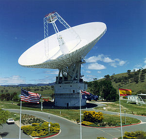
Parabolic antenna
A parabolic antenna is an antenna that uses a parabolic reflector, a curved surface with the cross-sectional shape of a parabola, to direct the radio waves. The most common form is shaped like a dish and is popularly called a dish antenna or parabolic dish...
s or horns
Horn antenna
A horn antenna or microwave horn is an antenna that consists of a flaring metal waveguide shaped like a horn to direct the radio waves. Horns are widely used as antennas at UHF and microwave frequencies, above 300 MHz...
, which serve to direct the radio waves into a beam or other desired radiation pattern
Radiation pattern
In the field of antenna design the term radiation pattern most commonly refers to the directional dependence of the strength of the radio waves from the antenna or other source ....
. Antennas can be designed to transmit or receive radio waves in all directions equally (omnidirectional antenna
Omnidirectional antenna
In radio communication, an omnidirectional antenna is an antenna which radiates radio wave power uniformly in all directions in one plane, with the radiated power decreasing with elevation angle above or below the plane, dropping to zero on the antenna's axis. This radiation pattern is often...
s), or transmit them in a beam in a particular direction, and receive from that one direction only (directional
Directional antenna
A directional antenna or beam antenna is an antenna which radiates greater power in one or more directions allowing for increased performance on transmit and receive and reduced interference from unwanted sources....
or high gain antennas).
The first antennas were built in 1888 by German physicist Heinrich Hertz in his pioneering experiments to prove the existence of electromagnetic waves predicted by the theory of James Clerk Maxwell
James Clerk Maxwell
James Clerk Maxwell of Glenlair was a Scottish physicist and mathematician. His most prominent achievement was formulating classical electromagnetic theory. This united all previously unrelated observations, experiments and equations of electricity, magnetism and optics into a consistent theory...
. Hertz placed dipole
Dipole
In physics, there are several kinds of dipoles:*An electric dipole is a separation of positive and negative charges. The simplest example of this is a pair of electric charges of equal magnitude but opposite sign, separated by some distance. A permanent electric dipole is called an electret.*A...
antennas at the focal point of parabolic reflector
Parabolic reflector
A parabolic reflector is a reflective device used to collect or project energy such as light, sound, or radio waves. Its shape is that of a circular paraboloid, that is, the surface generated by a parabola revolving around its axis...
s for both transmitting and receiving. He published his work in Annalen der Physik und Chemie (vol. 36, 1889).
Terminology
The words antenna (plural: antennas) and aerial are used interchangeably; but usually a rigid metallic structure is termed an antenna and a wire format is called an aerial. In the United KingdomUnited Kingdom
The United Kingdom of Great Britain and Northern IrelandIn the United Kingdom and Dependencies, other languages have been officially recognised as legitimate autochthonous languages under the European Charter for Regional or Minority Languages...
and other British English
British English
British English, or English , is the broad term used to distinguish the forms of the English language used in the United Kingdom from forms used elsewhere...
speaking areas the term aerial is more common, even for rigid types. The noun aerial is occasionally written with a diaeresis mark—aërial—in recognition of the original spelling of the adjective aërial from which the noun is derived.
The origin of the word antenna relative to wireless apparatus is attributed to Italian radio pioneer Guglielmo Marconi
Guglielmo Marconi
Guglielmo Marconi was an Italian inventor, known as the father of long distance radio transmission and for his development of Marconi's law and a radio telegraph system. Marconi is often credited as the inventor of radio, and indeed he shared the 1909 Nobel Prize in Physics with Karl Ferdinand...
. In 1895, while testing early radio apparatus in the Swiss Alps
Swiss Alps
The Swiss Alps are the portion of the Alps mountain range that lies within Switzerland. Because of their central position within the entire Alpine range, they are also known as the Central Alps....
at Salvan, Switzerland
Salvan, Switzerland
Salvan is a municipality in the district of Saint-Maurice, in the canton of Valais, Switzerland.-History:Salvan is first mentioned in 1018 as cum Silvano. Around 1025-31 it was mentioned as in monte Salvano. The municipality was formerly known by its German name Scharwang, however, that name is...
in the Mont Blanc
Mont Blanc
Mont Blanc or Monte Bianco , meaning "White Mountain", is the highest mountain in the Alps, Western Europe and the European Union. It rises above sea level and is ranked 11th in the world in topographic prominence...
region, Marconi experimented with long wire 'aerials'. He used a 2.5 meter vertical pole, with a wire attached to the top running down to the transmitter, as a radiating and receiving aerial element. In Italian a tent pole is known as l'antenna centrale, and the pole with the wire was simply called l'antenna. Until then wireless radiating transmitting and receiving elements were known simply as aerials or terminals. Because of his prominence, Marconi's use of the word antenna (Italian
Italian language
Italian is a Romance language spoken mainly in Europe: Italy, Switzerland, San Marino, Vatican City, by minorities in Malta, Monaco, Croatia, Slovenia, France, Libya, Eritrea, and Somalia, and by immigrant communities in the Americas and Australia...
for pole) spread among wireless researchers, and later to the general public.
In common usage, the word antenna may refer broadly to an entire assembly including support structure, enclosure (if any), etc. in addition to the actual functional components. Especially at microwave frequencies, a receiving antenna may include not only the actual electrical antenna but an integrated preamplifier and/or mixer
Frequency mixer
In electronics a mixer or frequency mixer is a nonlinear electrical circuit that creates new frequencies from two signals applied to it. In its most common application, two signals at frequencies f1 and f2 are applied to a mixer, and it produces new signals at the sum f1 + f2 and difference f1 -...
.
Overview
Antennas are required by any radio receiver or transmitter to couple its electrical connection to the electromagnetic field. RadioRadio
Radio is the transmission of signals through free space by modulation of electromagnetic waves with frequencies below those of visible light. Electromagnetic radiation travels by means of oscillating electromagnetic fields that pass through the air and the vacuum of space...
waves are electromagnetic waves which carry signals through the air (or through space) at the speed of light
Speed of light
The speed of light in vacuum, usually denoted by c, is a physical constant important in many areas of physics. Its value is 299,792,458 metres per second, a figure that is exact since the length of the metre is defined from this constant and the international standard for time...
with almost no transmission loss
Absorption (electromagnetic radiation)
In physics, absorption of electromagnetic radiation is the way by which the energy of a photon is taken up by matter, typically the electrons of an atom. Thus, the electromagnetic energy is transformed to other forms of energy for example, to heat. The absorption of light during wave propagation is...
. Radio transmitters and receivers are used to convey signals (information) in systems including broadcast (audio) radio, television
Television
Television is a telecommunication medium for transmitting and receiving moving images that can be monochrome or colored, with accompanying sound...
, mobile telephones, wi-fi
Wi-Fi
Wi-Fi or Wifi, is a mechanism for wirelessly connecting electronic devices. A device enabled with Wi-Fi, such as a personal computer, video game console, smartphone, or digital audio player, can connect to the Internet via a wireless network access point. An access point has a range of about 20...
(WLAN) data networks, trunk lines
Trunking
In modern communications, trunking is a concept by which a communications system can provide network access to many clients by sharing a set of lines or frequencies instead of providing them individually. This is analogous to the structure of a tree with one trunk and many branches. Examples of...
and point-to-point communications links (telephone, data networks), satellite links, many remote controlled devices such as garage door opener
Garage door opener
A garage door opener is a motorized device that opens and closes garage doors. Most are controlled by switches on the garage wall, as well as by remote controls carried in the garage owner's cars, or more rarely, on keychains.- The electric opener :...
s, and wireless remote sensors, among many others. Radio waves are also used directly for measurements in technologies including RADAR
Radar
Radar is an object-detection system which uses radio waves to determine the range, altitude, direction, or speed of objects. It can be used to detect aircraft, ships, spacecraft, guided missiles, motor vehicles, weather formations, and terrain. The radar dish or antenna transmits pulses of radio...
, GPS, and radio astronomy
Radio astronomy
Radio astronomy is a subfield of astronomy that studies celestial objects at radio frequencies. The initial detection of radio waves from an astronomical object was made in the 1930s, when Karl Jansky observed radiation coming from the Milky Way. Subsequent observations have identified a number of...
. In each and every case, the transmitters and receivers involved require antennas, although these are sometimes hidden (such as the antenna inside an AM radio or inside a laptop computer equipped with wi-fi).
According to their applications and technology available, antennas generally fall in one of two categories:
- OmnidirectionalOmnidirectional antennaIn radio communication, an omnidirectional antenna is an antenna which radiates radio wave power uniformly in all directions in one plane, with the radiated power decreasing with elevation angle above or below the plane, dropping to zero on the antenna's axis. This radiation pattern is often...
or only weakly directional antennas which receive or radiate more or less in all directions. These are employed when the relative position of the other station is unknown or arbitrary. They are also used at lower frequencies where a directional antenna would be too large, or simply to cut costs in applications where a directional antenna isn't required. - DirectionalDirectional antennaA directional antenna or beam antenna is an antenna which radiates greater power in one or more directions allowing for increased performance on transmit and receive and reduced interference from unwanted sources....
or beam antennas which are intended to preferentially radiate or receive in a particular direction or directional pattern.
In common usage "omnidirectional" usually refers to all horizontal directions, typically with reduced performance in the direction of the sky or the ground (a truly isotropic radiator is not even possible). A "directional" antenna usually is intended to maximize its coupling to the electromagnetic field in the direction of the other station, or sometimes to cover a particular sector such as a 120° horizontal fan pattern in the case of a panel antenna at a cell site
Cell site
A cell site is a term used to describe a site where antennas and electronic communications equipment are placed, usually on a radio mast, tower or other high place, to create a cell in a cellular network...
.
One example of omnidirectional antennas is the very common vertical antenna or whip antenna
Whip antenna
A whip antenna is an antenna consisting of a single straight flexible wire or rod, often mounted above some type of conducting surface called a ground plane. The bottom end of the whip is connected to the radio receiver or transmitter. They are designed to be flexible so that they won't break...
consisting of a metal rod (often, but not always, a quarter of a wavelength long). A dipole antenna
Dipole antenna
A dipole antenna is a radio antenna that can be made of a simple wire, with a center-fed driven element. It consists of two metal conductors of rod or wire, oriented parallel and collinear with each other , with a small space between them. The radio frequency voltage is applied to the antenna at...
is similar but consists of two such conductors extending in opposite directions, with a total length that is often, but not always, a half of a wavelength long. Dipoles are typically oriented horizontally in which case they are weakly directional: signals are reasonably well radiated toward or received from all directions with the exception of the direction along the conductor itself; this region is called the antenna blind cone or null.
Both the vertical and dipole antennas are simple in construction and relatively inexpensive. The dipole antenna, which is the basis for most antenna designs, is a balanced component, with equal but opposite voltages and currents applied at its two terminals through a balanced transmission line
Balanced line
In telecommunications and professional audio, a balanced line or balanced signal pair is a transmission line consisting of two conductors of the same type, each of which have equal impedances along their lengths and equal impedances to ground and to other circuits. The chief advantage of the...
(or to a coaxial transmission line through a so-called balun
Balun
A balun is a type of electrical transformer that can convert electrical signals that are balanced about ground to signals that are unbalanced , and the reverse. They are also often used to connect lines of differing impedance...
). The vertical antenna, on the other hand, is a monopole antenna. It is typically connected to the inner conductor of a coaxial transmission line
Coaxial cable
Coaxial cable, or coax, has an inner conductor surrounded by a flexible, tubular insulating layer, surrounded by a tubular conducting shield. The term coaxial comes from the inner conductor and the outer shield sharing the same geometric axis...
(or a matching network); the shield of the transmission line is connected to ground
Ground (electricity)
In electrical engineering, ground or earth may be the reference point in an electrical circuit from which other voltages are measured, or a common return path for electric current, or a direct physical connection to the Earth....
. In this way, the ground (or any large conductive surface) plays the role of the second conductor of a dipole, thereby forming a complete circuit. Since monopole antennas rely on a conductive ground, a so-called ground
Ground (electricity)
In electrical engineering, ground or earth may be the reference point in an electrical circuit from which other voltages are measured, or a common return path for electric current, or a direct physical connection to the Earth....
ing structure may be employed to provide a better ground contact to the earth or which itself acts as a ground plane
Ground plane
In electrical engineering, a ground plane is an electrically conductive surface.-Radio antenna theory :In telecommunication, a ground plane structure or relationship exists between the antenna and another object, where the only structure of the object is a structure which permits the antenna to...
to perform that function regardless of (or in absence of) an actual contact with the earth.
Antennas fancier than the dipole or vertical designs are usually intended to increase the directivity and consequently the gain of the antenna. This can be accomplished in many different ways leading to a plethora of antenna designs. The vast majority of designs are fed with a balanced line (unlike a monopole antenna) and are based on the dipole antenna with additional components (or elements) which increase its directionality.
For instance, a phased array
Phased array
In wave theory, a phased array is an array of antennas in which the relative phases of the respective signals feeding the antennas are varied in such a way that the effective radiation pattern of the array is reinforced in a desired direction and suppressed in undesired directions.An antenna array...
consists of two or more simple antennas which are connected together through an electrical network. This often involves a number of parallel dipole antennas with a certain spacing. Depending on the relative phase
Phase (waves)
Phase in waves is the fraction of a wave cycle which has elapsed relative to an arbitrary point.-Formula:The phase of an oscillation or wave refers to a sinusoidal function such as the following:...
introduced by the network, the same combination of dipole antennas can operate as a "broadside array" (directional normal to a line connecting the elements) or as an "end-fire array" (directional along the line connecting the elements). Antenna arrays may employ any basic (omnidirectional or weakly directional) antenna type, such as dipole, loop or slot antennas. These elements are often identical.
However a log-periodic dipole array
Log-periodic antenna
In telecommunication, a log-periodic antenna is a broadband, multi-element, unidirectional, narrow-beam antenna that has impedance and radiation characteristics that are regularly repetitive as a logarithmic function of the excitation frequency...
consists of a number of dipole elements of different lengths in order to obtain a somewhat directional antenna having an extremely wide bandwidth: these are frequently used for television reception in fringe areas. The dipole antennas composing it are all considered "active elements" since they are all electrically connected together (and to the transmission line). On the other hand, a superficially similar dipole array, the Yagi-Uda Antenna (or simply "Yagi"), has only one dipole element with an electrical connection; the other so-called parasitic elements interact with the electromagnetic field in order to realize a fairly directional antenna but one which is limited to a rather narrow bandwidth. The Yagi antenna has similar looking parasitic dipole elements but which act differently due to their somewhat different lengths. There may be a number of so-called "directors" in front of the active element in the direction of propagation, and usually a single (but possibly more) "reflector" on the opposite side of the active element.
Greater directionality can be obtained using beam-forming techniques such as a parabolic reflector
Parabolic reflector
A parabolic reflector is a reflective device used to collect or project energy such as light, sound, or radio waves. Its shape is that of a circular paraboloid, that is, the surface generated by a parabola revolving around its axis...
or a horn. Since the size of a directional antenna depends on it being large compared to the wavelength, very directional antennas of this sort are mainly feasible at UHF and microwave frequencies. On the other hand, at low frequencies (such as AM broadcast) where a practical antenna must be much smaller than a wavelength, significant directionality isn't even possible. A vertical antenna or loop antenna small compared to the wavelength is typically used, with the main design challenge being that of impedance matching
Impedance matching
In electronics, impedance matching is the practice of designing the input impedance of an electrical load to maximize the power transfer and/or minimize reflections from the load....
. With a vertical antenna a loading coil at the base of the antenna may be employed to cancel the reactive component of impedance; small loop antennas are tuned with parallel capacitors for this purpose.
An antenna lead-in is the transmission line
Transmission line
In communications and electronic engineering, a transmission line is a specialized cable designed to carry alternating current of radio frequency, that is, currents with a frequency high enough that its wave nature must be taken into account...
(or feed line
Feed line
In a radio antenna, the feed line is the cable or other transmission line that connects the antenna with the radio transmitter or receiver. In a transmitter, it feeds the radio frequency current from the transmitter to the antenna, where it is radiated as radio waves. In a receiver it transfers...
) which connects the antenna to a transmitter or receiver. The antenna feed
Antenna feed
In telecommunications and electronics, an antenna feed refers to the components of an antenna which feed the radio waves to the rest of the antenna structure, or in receiving antennas collect the incoming radio waves, convert them to electric currents and transmit them to the receiver...
may refer to all components connecting the antenna to the transmitter or receiver, such as an impedance matching
Impedance matching
In electronics, impedance matching is the practice of designing the input impedance of an electrical load to maximize the power transfer and/or minimize reflections from the load....
network in addition to the transmission line. In a so-called aperture antenna, such as a horn or parabolic dish, the "feed" may also refer to a basic antenna inside the entire system (normally at the focus of the parabolic dish or at the throat of a horn) which could be considered the one active element in that antenna system. A microwave antenna may also be fed directly from a waveguide
Waveguide
A waveguide is a structure which guides waves, such as electromagnetic waves or sound waves. There are different types of waveguides for each type of wave...
in lieu of a (conductive) transmission line
Transmission line
In communications and electronic engineering, a transmission line is a specialized cable designed to carry alternating current of radio frequency, that is, currents with a frequency high enough that its wave nature must be taken into account...
.
An antenna counterpoise
Counterpoise (ground system)
A counterpoise is a type of electrical ground that is not connected to earth. It is used in radio antenna systems when a normal earth ground cannot be used because of high soil resistance It consists of a network of wires or cables running parallel to the ground, suspended from a few centimetres...
or ground plane
Ground plane
In electrical engineering, a ground plane is an electrically conductive surface.-Radio antenna theory :In telecommunication, a ground plane structure or relationship exists between the antenna and another object, where the only structure of the object is a structure which permits the antenna to...
is a structure of conductive material which improves or substitutes for the ground. It may be connected to or insulated from the natural ground. In a monopole antenna, this aids in the function of the natural ground, particularly where variations (or limitations) of the characteristics of the natural ground interfere with its proper function. Such a structure is normally connected to the return connection of an unbalanced transmission line such as the shield of a coaxial cable
Coaxial cable
Coaxial cable, or coax, has an inner conductor surrounded by a flexible, tubular insulating layer, surrounded by a tubular conducting shield. The term coaxial comes from the inner conductor and the outer shield sharing the same geometric axis...
.
An electromagnetic wave refractor in some aperture antennas is a component which due to its shape and position functions to selectively delay or advance portions of the electromagnetic wavefront passing through it. The refractor alters the spatial characteristics of the wave on one side relative to the other side. It can, for instance, bring the wave to a focus or alter the wave front in other ways, generally in order to maximize the directivity of the antenna system. This is the radio equivalent of an optical lens.
An antenna coupling network is a passive network (generally a combination of inductive and capacitive circuit elements) used for impedance matching
Impedance matching
In electronics, impedance matching is the practice of designing the input impedance of an electrical load to maximize the power transfer and/or minimize reflections from the load....
in between the antenna and the transmitter or receiver. This may be used to improve the standing wave ratio
Standing wave ratio
In telecommunications, standing wave ratio is the ratio of the amplitude of a partial standing wave at an antinode to the amplitude at an adjacent node , in an electrical transmission line....
in order to minimize losses in the transmission line (especially at higher frequencies and/or over longer distances) and to present the transmitter or receiver with a standard resistive impedance (such as 75 ohms) that it expects to see for optimum operation.
Reciprocity
It is a fundamental property of antennas that the electrical characteristics of an antenna described in the next section, such as gainAntenna gain
In electromagnetics, an antenna's power gain or simply gain is a key performance figure which combines the antenna's directivity and electrical efficiency. As a transmitting antenna, the figure describes how well the antenna converts input power into radio waves headed in a specified direction...
, radiation pattern
Radiation pattern
In the field of antenna design the term radiation pattern most commonly refers to the directional dependence of the strength of the radio waves from the antenna or other source ....
, impedance
Electrical impedance
Electrical impedance, or simply impedance, is the measure of the opposition that an electrical circuit presents to the passage of a current when a voltage is applied. In quantitative terms, it is the complex ratio of the voltage to the current in an alternating current circuit...
, bandwidth, resonant frequency and polarization, are the same whether the antenna is transmitting
Transmitter
In electronics and telecommunications a transmitter or radio transmitter is an electronic device which, with the aid of an antenna, produces radio waves. The transmitter itself generates a radio frequency alternating current, which is applied to the antenna. When excited by this alternating...
or receiving. For example, the "receiving pattern" (sensitivity as a function of direction) of an antenna when used for reception is identical to the radiation pattern
Radiation pattern
In the field of antenna design the term radiation pattern most commonly refers to the directional dependence of the strength of the radio waves from the antenna or other source ....
of the antenna when it is driven and functions as a radiator. This is a consequence of the reciprocity theorem
Reciprocity (electromagnetism)
In classical electromagnetism, reciprocity refers to a variety of related theorems involving the interchange of time-harmonic electric current densities and the resulting electromagnetic fields in Maxwell's equations for time-invariant linear media under certain constraints...
of electromagnetics. Therefore in discussions of antenna properties no distinction is usually made between receiving and transmitting terminology, and the antenna can be viewed as either transmitting or receiving, whichever is more convenient.
A necessary condition for the aforementioned reciprocity property is that the materials in the antenna and transmission medium are linear
Linear function
In mathematics, the term linear function can refer to either of two different but related concepts:* a first-degree polynomial function of one variable;* a map between two vector spaces that preserves vector addition and scalar multiplication....
and reciprocal. Reciprocal (or bilateral) means that the material has the same response to an electric current or magnetic field in one direction, as it has to the field or current in the opposite direction. Most materials used in antennas meet these conditions, but some microwave antennas use high-tech components such as isolator
Isolator (microwave)
An isolator is a two-port device that transmits microwave or radio frequency power in one direction only. It is used to shield equipment on its input side, from the effects of conditions on its output side; for example, to prevent a microwave source being detuned by a mismatched...
s and circulator
Circulator
A circulator is a passive non-reciprocal three- or four-port device, in which microwave or radio frequency power entering any port is transmitted to the next port in rotation...
s, made of nonreciprocal materials such as ferrite
Ferrite
Ferrite may refer to:* Ferrite , iron or iron alloys with a body centred cubic crystal structure.* Ferrite , ferrimagnetic ceramic materials used in magnetic applications....
or garnet. These can be used to give the antenna a different behavior on receiving than it has on transmitting, which can be useful in applications like radar
Radar
Radar is an object-detection system which uses radio waves to determine the range, altitude, direction, or speed of objects. It can be used to detect aircraft, ships, spacecraft, guided missiles, motor vehicles, weather formations, and terrain. The radar dish or antenna transmits pulses of radio...
.
Parameters
Antennas are characterized by a number of performance measures which a user would be concerned with in selecting or designing an antenna for a particular application. Chief among these relate to the directional characteristics (as depicted in the antenna's radiation patternRadiation pattern
In the field of antenna design the term radiation pattern most commonly refers to the directional dependence of the strength of the radio waves from the antenna or other source ....
) and the resulting gain
Antenna gain
In electromagnetics, an antenna's power gain or simply gain is a key performance figure which combines the antenna's directivity and electrical efficiency. As a transmitting antenna, the figure describes how well the antenna converts input power into radio waves headed in a specified direction...
. Even in omnidirectional (or weakly directional) antennas, the gain can often be increased by concentrating more of its power in the horizontal directions, sacrificing power radiated toward the sky and ground. The antenna's power gain
Antenna gain
In electromagnetics, an antenna's power gain or simply gain is a key performance figure which combines the antenna's directivity and electrical efficiency. As a transmitting antenna, the figure describes how well the antenna converts input power into radio waves headed in a specified direction...
(or simply "gain") also takes into account the antenna's efficiency, and is often the primary figure of merit.
Resonant antennas are expected to be used around a particular resonant frequency
Resonance
In physics, resonance is the tendency of a system to oscillate at a greater amplitude at some frequencies than at others. These are known as the system's resonant frequencies...
; an antenna must therefore be built or ordered to match the frequency range of the intended application. A particular antenna design will present a particular feedpoint impedance
Electrical impedance
Electrical impedance, or simply impedance, is the measure of the opposition that an electrical circuit presents to the passage of a current when a voltage is applied. In quantitative terms, it is the complex ratio of the voltage to the current in an alternating current circuit...
. While this may affect the choice of an antenna, an antenna's impedance can also be adapted to the desired impedance level of a system using an matching network
Impedance matching
In electronics, impedance matching is the practice of designing the input impedance of an electrical load to maximize the power transfer and/or minimize reflections from the load....
while maintaining the other characteristics (except for a possible loss of efficiency).
Although these parameters can be measured
Antenna measurement
Antenna measurement techniques refers to the testing of antennas to ensure that the antenna meets specifications or simply to characterize it. Typical parameters of antennas are gain, radiation pattern, beamwidth, polarization, and impedance....
in principle, such measurements are difficult and require very specialized equipment. Beyond tuning a transmitting antenna using an SWR
Standing wave ratio
In telecommunications, standing wave ratio is the ratio of the amplitude of a partial standing wave at an antinode to the amplitude at an adjacent node , in an electrical transmission line....
meter, the typical user will depend on theoretical predictions based on the antenna design and/or on claims of a vendor.
An antenna transmits and receives radio waves with a particular polarization which can be reoriented by tilting the axis of the antenna in many (but not all) cases. The physical size of an antenna is often a practical issue, particularly at lower frequencies (longer wavelengths). Highly directional antennas need to be significantly larger than the wavelength. Resonant antennas use a conductor, or a pair of conductors, each of which is about one quarter of the wavelength in length. Antennas that are required to be very small compared to the wavelength sacrifice efficiency and cannot be very directional. Fortunately at higher frequencies (UHF, microwaves) trading off performance to obtain a smaller physical size is usually not required.
Resonant antennas
While there are broadband designs for antennas, the vast majority of antennas are based on the half-wave dipoleDipole antenna
A dipole antenna is a radio antenna that can be made of a simple wire, with a center-fed driven element. It consists of two metal conductors of rod or wire, oriented parallel and collinear with each other , with a small space between them. The radio frequency voltage is applied to the antenna at...
which has a particular resonant frequency. At its resonant frequency, the wavelength
Wavelength
In physics, the wavelength of a sinusoidal wave is the spatial period of the wave—the distance over which the wave's shape repeats.It is usually determined by considering the distance between consecutive corresponding points of the same phase, such as crests, troughs, or zero crossings, and is a...
(figured by dividing the speed of light
Speed of light
The speed of light in vacuum, usually denoted by c, is a physical constant important in many areas of physics. Its value is 299,792,458 metres per second, a figure that is exact since the length of the metre is defined from this constant and the international standard for time...
by the resonant frequency) is slightly over twice the length of the half-wave dipole (thus the name). The quarter-wave vertical antenna consists of one arm of a half-wave dipole, with the other arm replaced by a connection to ground
Ground
Ground may refer to:* Earth's surface* Soil, a mixture of clay, sand and organic matter present on the surface of the Earth and serving as substrate for plant growth and micro-organisms development...
or an equivalent ground plane
Ground plane
In electrical engineering, a ground plane is an electrically conductive surface.-Radio antenna theory :In telecommunication, a ground plane structure or relationship exists between the antenna and another object, where the only structure of the object is a structure which permits the antenna to...
(or counterpoise
Counterpoise
Counterpoise is an alternative review journal based in Gainesville, Florida . It was founded in 1997 by Charles Willett, as a project of the AIP Task Force of the American Library Association's Social Responsibilities Round Table. In January 2001, Counterpoise became a project of the Civic Media...
). A Yagi-Uda array consists of a number of resonant dipole elements, only one of which is directly connected to the transmission line. The quarter-wave elements of a dipole or vertical antenna imitate a series-resonant electrical element, since if they are driven at the resonant frequency a standing wave
Standing wave
In physics, a standing wave – also known as a stationary wave – is a wave that remains in a constant position.This phenomenon can occur because the medium is moving in the opposite direction to the wave, or it can arise in a stationary medium as a result of interference between two waves traveling...
is created with the peak current at the feed-point and the peak voltage at the far end.
A common misconception is that the ability of a resonant antenna to transmit (or receive) fails at frequencies far from the resonant frequency. The reason a dipole antenna needs to be used at the resonant frequency has to do with the impedance match between the antenna and the transmitter or receiver (and its transmission line). For instance, a dipole using a fairly thin conductor will have a purely resistive feedpoint impedance of about 63 ohms at its design frequency. Feeding that antenna with a current of 1 ampere will require 63 volts of RF, and the antenna will radiate 63 watts (ignoring losses) of radio frequency power. If that antenna is driven with 1 ampere at a frequency 20% higher, it will still radiate as efficiently but in order to do that about 200 volts would be required due to the change in the antenna's impedance which is now largely reactive (voltage out of phase with the current). A typical transmitter would not find that impedance acceptable and would deliver much less than 63 watts to it; the transmission line would be operating at a high (poor) standing wave ratio
Standing wave ratio
In telecommunications, standing wave ratio is the ratio of the amplitude of a partial standing wave at an antinode to the amplitude at an adjacent node , in an electrical transmission line....
. But using an appropriate matching network, that large reactive impedance could be converted to a resistive impedance satisfying the transmitter and accepting the available power of the transmitter.
This principle is used to construct vertical antennas substantially shorter than the 1/4 wavelength at which the antenna is resonant. By adding an inductance in series with the vertical antenna (a so-called loading coil) the capacitative reactance of this antenna can be cancelled leaving a pure resistance which can then be matched to the transmission line. Sometimes the resulting resonant frequency of such a system (antenna plus matching network) is described using the construct of "electrical length" and the use of a shorter antenna at a lower frequency than its resonant frequency is termed "electrical lengthening
Electrical lengthening
Electrical lengthening is the modification of an aerial which is shorter than a whole-number multiple of a quarter of the radiated wavelength, by means of a suitable electronic device, without changing the physical length of the aerial, in such a way that it corresponds electrically to the next...
". For example, at 30 MHz (wavelength = 10 meters) a true resonant monopole would be almost 2.5 meters (1/4 wavelength) long, and using an antenna only 1.5 meters tall would require the addition of a loading coil. Then it may be said that the coil has "lengthened" the antenna to achieve an "electrical length" of 2.5 meters, that is, 1/4 wavelength at 30 MHz where the combined system now resonates. However, the resulting resistive impedance achieved will be quite a bit lower than the impedance of a resonant monopole, likely requiring further impedance matching.
Current and voltage distribution
The antenna conductors have the lowest feed-point impedance at the resonant frequency where they are just under 1/4 wavelength long; two such conductors in line fed differentially thus realizes the familiar "half-wave dipole". When fed with an RF current at the resonant frequency, the quarter wave element contains a standing waveStanding wave
In physics, a standing wave – also known as a stationary wave – is a wave that remains in a constant position.This phenomenon can occur because the medium is moving in the opposite direction to the wave, or it can arise in a stationary medium as a result of interference between two waves traveling...
with the voltage and current largely (but not exactly) in phase quadrature, as would be obtained using a quarter wave stub of transmission line. The current reaches a minimum at the end of the element (where it has nowhere to go!) and is maximum at the feed-point. The voltage, on the other hand, is the greatest at the end of the conductor and reaches a minimum (but not zero) at the feedpoint. Making the conductor shorter or longer than 1/4 wavelength means that the voltage pattern reaches its minimum somewhere beyond the feed-point, so that the feed-point has a higher voltage and thus sees a higher impedance, as we have noted. Since that voltage pattern is almost in phase quadrature with the current, the impedance seen at the feed-point is not only much higher but mainly reactive.
It can be seen that if such an element is resonant at f0 to produce such a standing wave pattern, then feeding that element with 3f0 (whose wavelength is 1/3 that of f0) will lead to a standing wave pattern in which the voltage is likewise a minimum at the feed-point (and the current at a maximum there). Thus, an antenna element is also resonant when its length is 3/4 of a wavelength (3/2 wavelength for a complete dipole). This is true for all odd multiples of 1/4 wavelength, where the feed-point impedance is purely resistive, though larger than the resistive impedance of the 1/4 wave element. Although such an antenna is resonant and works perfectly well at the higher frequency, the antenna radiation pattern is also altered compared to the half-wave dipole.
The use of a monopole or dipole at odd multiples of the fundamental resonant frequency, however, does not extend to even multiples (thus a 1/2 wavelength monopole or 1 wavelength dipole). Now the voltage standing wave is at its peak at the feed-point, while that of the current (which must be zero at the end of the conductor) is at a minimum (but not exactly zero). The antenna is anti-resonant at this frequency. Although the reactance at the feedpoint can be cancelled using such an element length, the feed-point impedance is very high, and is highly dependent on the diameter of the conductor (which makes only a small difference at the actual resonant frequency). Such an antenna does not match the much lower characteristic impedance of available transmission lines, and is generally not used. However some equipment where transmission lines are not involved which desire a high driving point impedance may take advantage of this anti-resonance.
Bandwidth
Although a resonant antenna has a purely resistive feed-point impedance at a particular frequency, many (if not most) applications require using an antenna over a range of frequencies. An antenna's bandwidth specifies the range of frequencies over which its performance does not suffer due a poor impedance match. Also in the case of a Yagi-Uda array, the use of the antenna very far away from its design frequency reduces the antenna's directivity, thus reducing the usable bandwidth regardless of impedance matching.Except for the latter concern, the resonant frequency of a resonant antenna can always be altered by adjusting a suitable matching network. To do this efficiently one would require remotely adjusting a matching network at the site of the antenna, since simply adjusting a matching network at the transmitter (or receiver) would leave the transmission line with a poor standing wave ratio
Standing wave ratio
In telecommunications, standing wave ratio is the ratio of the amplitude of a partial standing wave at an antinode to the amplitude at an adjacent node , in an electrical transmission line....
.
Instead, it is often desired to have an antenna whose impedance does not vary so greatly over a certain bandwidth. It turns out that the amount of reactance seen at the terminals of a resonant antenna when the frequency is shifted, say, by 5%, depends very much on the diameter of the conductor used. A long thin wire used as a half-wave dipole (or quarter wave monopole) will have a reactance significantly greater than the resistive impedance it has at resonance, leading to a poor match and generally unacceptable performance. Making the element using a tube of a diameter perhaps 1/50 of its length, however, results in a reactance at this altered frequency which is not so great, and a much less serious mismatch which will only modestly damage the antenna's net performance. Thus rather thick tubes are typically used for the solid elements of such antennas, including Yagi-Uda arrays.
Rather than just using a thick tube, there are similar techniques used to the same effect such as replacing thin wire elements with cages to simulate a thicker element. This widens the bandwidth of the resonance. On the other hand, amateur radio antennas need to operate over several bands which are widely separated from each other. This can often be accomplished simply by connecting resonant elements for the different bands in parallel. Most of the transmitter's power will flow into the resonant element while the others present a high (reactive) impedance and draw little current from the same voltage. A popular solution uses so-called traps consisting of parallel resonant circuits which are strategically placed in breaks along each antenna element. When used at one particular frequency band the trap presents a very high impedance (parallel resonance) effectively truncating the element at that length, making it a proper resonant antenna. At a lower frequency the trap allows the full length of the element to be employed, albeit with a shifted resonant frequency due to the inclusion of the trap's net reactance at that lower frequency.
The bandwidth characteristics of a resonant antenna element can be characterized according to its Q
Q factor
In physics and engineering the quality factor or Q factor is a dimensionless parameter that describes how under-damped an oscillator or resonator is, or equivalently, characterizes a resonator's bandwidth relative to its center frequency....
, just as one uses to characterize the sharpness of an L-C resonant circuit
LC circuit
An LC circuit, also called a resonant circuit or tuned circuit, consists of an inductor, represented by the letter L, and a capacitor, represented by the letter C...
. However it is often assumed that there is an advantage in an antenna having a high Q
Q factor
In physics and engineering the quality factor or Q factor is a dimensionless parameter that describes how under-damped an oscillator or resonator is, or equivalently, characterizes a resonator's bandwidth relative to its center frequency....
. After all, Q is short for "quality factor" and a low Q typically signifies excessive loss (due to unwanted resistance) in a resonant L-C circuit
LC circuit
An LC circuit, also called a resonant circuit or tuned circuit, consists of an inductor, represented by the letter L, and a capacitor, represented by the letter C...
. However this understanding does not apply to resonant antennas where the resistance involved is the radiation resistance
Radiation resistance
Radiation resistance is that part of an antenna's feedpoint resistance that is caused by the radiation of electromagnetic waves from the antenna. The radiation resistance is determined by the geometry of the antenna, not by the materials of which it is made...
, a desired quantity which removes energy from the resonant element in order to radiate it (the purpose of an antenna, after all!). The Q is a measure of the ratio of reactance to resistance, so with a fixed radiation resistance
Radiation resistance
Radiation resistance is that part of an antenna's feedpoint resistance that is caused by the radiation of electromagnetic waves from the antenna. The radiation resistance is determined by the geometry of the antenna, not by the materials of which it is made...
(an element's radiation resistance is almost independent of its diameter) a greater reactance off-resonance corresponds to the poorer bandwidth of a very thin conductor. The Q of such a narrowband antenna can be as high as 15. On the other hand a thick element presents less reactance at an off-resonant frequency, and consequently a Q as low as 5. These two antennas will perform equivalently at the resonant frequency, but the second antenna will perform over a bandwidth 3 times as wide as the "hi-Q" antenna consisting of a thin conductor.
Gain
GainAntenna gain
In electromagnetics, an antenna's power gain or simply gain is a key performance figure which combines the antenna's directivity and electrical efficiency. As a transmitting antenna, the figure describes how well the antenna converts input power into radio waves headed in a specified direction...
is a parameter which measures the degree of directivity of the antenna's radiation pattern. A high-gain antenna will preferentially radiate in a particular direction. Specifically, the antenna gain, or power gain of an antenna is defined as the ratio of the intensity
Intensity (physics)
In physics, intensity is a measure of the energy flux, averaged over the period of the wave. The word "intensity" here is not synonymous with "strength", "amplitude", or "level", as it sometimes is in colloquial speech...
(power per unit surface) radiated by the antenna in the direction of its maximum output, at an arbitrary distance, divided by the intensity radiated at the same distance by a hypothetical isotropic antenna.
The gain of an antenna is a passive phenomenon - power is not added by the antenna, but simply redistributed to provide more radiated power in a certain direction than would be transmitted by an isotropic antenna. An antenna designer must take into account the application for the antenna when determining the gain. High-gain antennas have the advantage of longer range and better signal quality, but must be aimed carefully in a particular direction. Low-gain antennas have shorter range, but the orientation of the antenna is relatively inconsequential. For example, a dish antenna on a spacecraft is a high-gain device that must be pointed at the planet to be effective, whereas a typical Wi-Fi
Wi-Fi
Wi-Fi or Wifi, is a mechanism for wirelessly connecting electronic devices. A device enabled with Wi-Fi, such as a personal computer, video game console, smartphone, or digital audio player, can connect to the Internet via a wireless network access point. An access point has a range of about 20...
antenna in a laptop computer is low-gain, and as long as the base station is within range, the antenna can be in any orientation in space. It makes sense to improve horizontal range at the expense of reception above or below the antenna. Thus most antennas labelled "omnidirectional" really have some gain.
In practice, the half-wave dipole is taken as a reference instead of the isotropic radiator. The gain is then given in dBd (decibels over dipole):
-
- NOTE: 0 dBd = 2.15 dBi. It is vital in expressing gain values that the reference point be included. Failure to do so can lead to confusion and error.
Effective area or aperture
The effective areaAntenna effective area
In telecommunications, antenna effective area or effective aperture expresses an antenna's ability to collect an incident radio wave and deliver it as an electrical current at the antenna's terminals...
or effective aperture of a receiving antenna expresses the portion of the power of a passing electromagnetic wave which it delivers to its terminals, expressed in terms of an equivalent area. For instance, if a radio wave passing a given location has a flux of 1 pW / m2 (10−12 watts per square meter) and an antenna has an effective area of 12 m2, then the antenna would deliver 12 pW of RF
Radio frequency
Radio frequency is a rate of oscillation in the range of about 3 kHz to 300 GHz, which corresponds to the frequency of radio waves, and the alternating currents which carry radio signals...
power to the receiver (30 microvolts rms
Root mean square
In mathematics, the root mean square , also known as the quadratic mean, is a statistical measure of the magnitude of a varying quantity. It is especially useful when variates are positive and negative, e.g., sinusoids...
at 75 ohms). Since the receiving antenna is not equally sensitive to signals received from all directions, the effective area is a function of the direction to the source.
Due to reciprocity
Reciprocity (electromagnetism)
In classical electromagnetism, reciprocity refers to a variety of related theorems involving the interchange of time-harmonic electric current densities and the resulting electromagnetic fields in Maxwell's equations for time-invariant linear media under certain constraints...
(discussed above) the gain of an antenna used for transmitting must be proportional to its effective area when used for receiving. Consider an antenna with no loss
Copper loss
Copper loss is the term often given to heat produced by electrical currents in the conductors of transformer windings, or other electrical devices. Copper losses are an undesirable transfer of energy, as are core losses, which result from induced currents in adjacent components...
, that is, one whose electrical efficiency
Antenna efficiency
In electromagnetics, antenna efficiency or radiation efficiency is a figure of merit for an antenna. It measures the electrical losses that occur throughout the antenna while it is operating at a given frequency, or averaged over its operation across a frequency band...
is 100%. It can be shown that its effective area averaged over all directions must be equal to λ2/4π, the wavelength squared divided by 4π. Gain is defined such that the average gain over all directions for an antenna with 100% electrical efficiency
Antenna efficiency
In electromagnetics, antenna efficiency or radiation efficiency is a figure of merit for an antenna. It measures the electrical losses that occur throughout the antenna while it is operating at a given frequency, or averaged over its operation across a frequency band...
is equal to 1. Therefore the effective area Aeff in terms of the gain G in a given direction is given by:

For an antenna with an efficiency
Antenna efficiency
In electromagnetics, antenna efficiency or radiation efficiency is a figure of merit for an antenna. It measures the electrical losses that occur throughout the antenna while it is operating at a given frequency, or averaged over its operation across a frequency band...
of less than 100%, both the effective area and gain are reduced by that same amount. Therefore the above relationship between gain and effective area still holds. These are thus two different ways of expressing the same quantity. Aeff is especially convenient when computing the power that would be received by an antenna of a specified gain, as illustrated by the above example.
Radiation pattern
The radiation patternRadiation pattern
In the field of antenna design the term radiation pattern most commonly refers to the directional dependence of the strength of the radio waves from the antenna or other source ....
of an antenna is a plot of the relative field strength of the radio waves emitted by the antenna at different angles. It is typically represented by a three dimensional graph, or polar plots of the horizontal and vertical cross sections. The pattern of an ideal isotropic antenna
Isotropic radiator
An isotropic radiator is a theoretical point source of electromagnetic or sound waves which radiates the same intensity of radiation in all directions. It has no preferred direction of radiation. It radiates uniformly in all directions over a sphere centred on the source...
, which radiates equally in all directions, would look like a sphere
Sphere
A sphere is a perfectly round geometrical object in three-dimensional space, such as the shape of a round ball. Like a circle in two dimensions, a perfect sphere is completely symmetrical around its center, with all points on the surface lying the same distance r from the center point...
. Many nondirectional antennas, such as monopoles
Monopole antenna
A monopole antenna is a class of radio antenna consisting of a straight rod-shaped conductor, often mounted perpendicularly over some type of conductive surface, called a ground plane. The driving signal from the transmitter is applied, or for receiving antennas the output voltage is taken,...
and dipoles
Dipole antenna
A dipole antenna is a radio antenna that can be made of a simple wire, with a center-fed driven element. It consists of two metal conductors of rod or wire, oriented parallel and collinear with each other , with a small space between them. The radio frequency voltage is applied to the antenna at...
, emit equal power in all horizontal directions, with the power dropping off at higher and lower angles; this is called an omnidirectional pattern
Omnidirectional antenna
In radio communication, an omnidirectional antenna is an antenna which radiates radio wave power uniformly in all directions in one plane, with the radiated power decreasing with elevation angle above or below the plane, dropping to zero on the antenna's axis. This radiation pattern is often...
and when plotted looks like a torus
Torus
In geometry, a torus is a surface of revolution generated by revolving a circle in three dimensional space about an axis coplanar with the circle...
or donut.
The radiation of many antennas shows a pattern of maxima or "lobes" at various angles, separated by "null
Null
-In computing:* Null , a special marker and keyword in SQL* Null character, the zero-valued ASCII character, also designated by NUL, often used as a terminator, separator or filler* Null device, a special computer file that discards all data written to it...
s", angles where the radiation falls to zero. This is because the radio waves emitted by different parts of the antenna typically interfere, causing maxima at angles where the radio waves arrive at distant points in phase, and zero radiation at other angles where the radio waves arrive out of phase. In a directional antenna
Directional antenna
A directional antenna or beam antenna is an antenna which radiates greater power in one or more directions allowing for increased performance on transmit and receive and reduced interference from unwanted sources....
designed to project radio waves in a particular direction, the lobe in that direction is designed larger than the others and is called the "main lobe". The other lobes usually represent unwanted radiation and are called "sidelobes". The axis through the main lobe is called the "principle axis" or "boresight
Antenna boresight
In telecommunications and radar engineering, antenna boresight is the axis of maximum gain ) of a directional antenna. For most antennas the boresight is the axis of symmetry of the antenna...
axis".
Impedance
As an electro-magnetic wave travels through the different parts of the antenna system (radio, feed line, antenna, free space) it may encounter differences in impedance (E/H, V/I, etc.). At each interface, depending on the impedance match, some fraction of the wave's energy will reflect back to the source, forming a standing wave in the feed line. The ratio of maximum power to minimum power in the wave can be measured and is called the standing wave ratioStanding wave ratio
In telecommunications, standing wave ratio is the ratio of the amplitude of a partial standing wave at an antinode to the amplitude at an adjacent node , in an electrical transmission line....
(SWR). A SWR of 1:1 is ideal. A SWR of 1.5:1 is considered to be marginally acceptable in low power applications where power loss is more critical, although an SWR as high as 6:1 may still be usable with the right equipment. Minimizing impedance differences at each interface (impedance matching
Impedance matching
In electronics, impedance matching is the practice of designing the input impedance of an electrical load to maximize the power transfer and/or minimize reflections from the load....
) will reduce SWR and maximize power transfer through each part of the antenna system.
Complex
Complex number
A complex number is a number consisting of a real part and an imaginary part. Complex numbers extend the idea of the one-dimensional number line to the two-dimensional complex plane by using the number line for the real part and adding a vertical axis to plot the imaginary part...
impedance of an antenna is related to the electrical length of the antenna at the wavelength in use. The impedance of an antenna can be matched to the feed line and radio by adjusting the impedance of the feed line, using the feed line as an impedance transformer
Transformer
A transformer is a device that transfers electrical energy from one circuit to another through inductively coupled conductors—the transformer's coils. A varying current in the first or primary winding creates a varying magnetic flux in the transformer's core and thus a varying magnetic field...
. More commonly, the impedance is adjusted at the load (see below) with an antenna tuner
Antenna tuner
An antenna tuner, transmatch or antenna tuning unit is a device connected between a radio transmitter or receiver and its antenna to improve the efficiency of the power transfer between them by matching the impedance of the equipment to the antenna...
, a balun
Balun
A balun is a type of electrical transformer that can convert electrical signals that are balanced about ground to signals that are unbalanced , and the reverse. They are also often used to connect lines of differing impedance...
, a matching transformer, matching networks composed of inductor
Inductor
An inductor is a passive two-terminal electrical component used to store energy in a magnetic field. An inductor's ability to store magnetic energy is measured by its inductance, in units of henries...
s and capacitor
Capacitor
A capacitor is a passive two-terminal electrical component used to store energy in an electric field. The forms of practical capacitors vary widely, but all contain at least two electrical conductors separated by a dielectric ; for example, one common construction consists of metal foils separated...
s, or matching sections such as the gamma match.
Efficiency
Efficiency of a transmitting antenna is the ratio of power actually radiated (in all directions) to the power absorbed by the antenna terminals. The power supplied to the antenna terminals which is not radiated is converted into heat. This is usually through loss resistanceCopper loss
Copper loss is the term often given to heat produced by electrical currents in the conductors of transformer windings, or other electrical devices. Copper losses are an undesirable transfer of energy, as are core losses, which result from induced currents in adjacent components...
in the antenna's conductors, but can also be due to dielectric or magnetic core losses in antennas (or antenna systems) using such components. Such loss effectively robs power from the transmitter, requiring a stronger transmitter in order to transmit a signal of a given strength.
For instance, if a transmitter delivers 100 W into an antenna having an efficiency of 80%, then the antenna will radiate 80 W as radio waves and produce 20 W of heat. In order to radiate 100 W of power, one would need to use a transmitter capable of supplying 125 W to the antenna. Note that antenna efficiency is a separate issue from impedance matching
Impedance matching
In electronics, impedance matching is the practice of designing the input impedance of an electrical load to maximize the power transfer and/or minimize reflections from the load....
, which may also reduce the amount of power radiated using a given transmitter. If an SWR
Standing wave ratio
In telecommunications, standing wave ratio is the ratio of the amplitude of a partial standing wave at an antinode to the amplitude at an adjacent node , in an electrical transmission line....
meter reads 150 W of incident power and 50 W of reflected power, that means that 100 W have actually been absorbed by the antenna (ignoring transmission line losses). How much of that power has actually been radiated cannot be directly determined through electrical measurements at (or before) the antenna terminals, but would require (for instance) careful measurement of field strength
Field strength
In physics, the field strength of a field is the magnitude of its vector value.In theoretical physics, field strength is another name for the curvature form...
. Fortunately the loss resistance of antenna conductors such as aluminum rods can be calculated and the efficiency of an antenna using such materials predicted.
However loss resistance
Copper loss
Copper loss is the term often given to heat produced by electrical currents in the conductors of transformer windings, or other electrical devices. Copper losses are an undesirable transfer of energy, as are core losses, which result from induced currents in adjacent components...
will generally affect the feedpoint impedance, adding to its resistive (real) component. That resistance will consist of the sum of the radiation resistance
Radiation resistance
Radiation resistance is that part of an antenna's feedpoint resistance that is caused by the radiation of electromagnetic waves from the antenna. The radiation resistance is determined by the geometry of the antenna, not by the materials of which it is made...
Rr and the loss resistance Rloss. If an rms
Root mean square
In mathematics, the root mean square , also known as the quadratic mean, is a statistical measure of the magnitude of a varying quantity. It is especially useful when variates are positive and negative, e.g., sinusoids...
current I is delivered to the terminals of an antenna, then a power of I2Rr will be radiated and a power of I2Rloss will be lost as heat. Therefore the efficiency of an antenna is equal to Rr / (Rr + Rloss). Of course only the total resistance Rr + Rloss can be directly measured.

Reciprocity (electromagnetism)
In classical electromagnetism, reciprocity refers to a variety of related theorems involving the interchange of time-harmonic electric current densities and the resulting electromagnetic fields in Maxwell's equations for time-invariant linear media under certain constraints...
, the efficiency of an antenna, when used as a receiving antenna, is identical to the efficiency as defined above. The power that an antenna will deliver to a receiver (with a proper impedance match) is reduced by the same amount. However often in a receiving application, inefficiency of an antenna may be of lesser consequence or even of no consequence, notably at lower frequencies or when used to receive signals in "crowded" bands. That is true in cases where the received signal competes not against receiver noise, but against atmospheric noise or interference received by the antenna itself. The loss within the antenna will affect the intended signal and the noise/interference identically, leading to no reduction in signal to noise ratio (SNR). According to the graph shown illustrating the frequency dependence of atmospheric and man-made noise, one can see that using a receiving antenna with an efficiency of only 10% at frequencies below 10 MHz will still supply a signal to the receiver which includes noise well above the thermal limit. A decent RF amplifier in the receiver will not significantly add to this noise level or reduce the resulting SNR.
This is fortunate, since antennas at lower frequencies which are not rather large (a good fraction of a wavelength in size) are inevitably inefficient (due to the small radiation resistance Rr of small antennas). Most AM broadcast radios (except for car radios) take advantage of this principle by including a small loop antenna for reception which has an extremely poor efficiency. Using such an inefficient antenna at this low frequency (530–1650 kHz) thus has little effect on the receiver's net performance, but simply requires greater amplification by the receiver's electronics. Contrast this tiny component to the massive and very tall towers used at AM broadcast stations for transmitting at the very same frequency, where every percentage point of reduced antenna efficiency entails a substantial cost.
The definition of antenna gain
Antenna gain
In electromagnetics, an antenna's power gain or simply gain is a key performance figure which combines the antenna's directivity and electrical efficiency. As a transmitting antenna, the figure describes how well the antenna converts input power into radio waves headed in a specified direction...
or power gain already includes the effect of the antenna's efficiency. Therefore if one is trying to radiate a signal toward a receiver using a transmitter of a given power, one need only compare the gain of various antennas rather than considering the efficiency as well. This is likewise true for a receiving antenna at very high (especially microwave) frequencies, where the point is to receive a signal which is strong compared to the receiver's noise temperature. However in the case of a directional antenna used for receiving signals with the intention of rejecting interference from different directions, one is no longer concerned with the antenna efficiency, as discussed above. In this case, rather than quoting the antenna gain
Antenna gain
In electromagnetics, an antenna's power gain or simply gain is a key performance figure which combines the antenna's directivity and electrical efficiency. As a transmitting antenna, the figure describes how well the antenna converts input power into radio waves headed in a specified direction...
, one would be more concerned with the directive gain which does not include the effect of antenna (in)efficiency. The directive gain of an antenna can be computed from the published gain divided by the antenna's efficiency.
Polarization
The polarization of an antenna is the orientation of the electric field (E-plane) of the radio wave with respect to the Earth's surface and is determined by the physical structure of the antenna and by its orientation. It has nothing in common with antenna directionality terms: "horizontal", "vertical", and "circular". Thus, a simple straight wire antenna will have one polarization when mounted vertically, and a different polarization when mounted horizontally. "Electromagnetic wave polarization filters" are structures which can be employed to act directly on the electromagnetic wave to filter out wave energy of an undesired polarization and to pass wave energy of a desired polarization.Reflections generally affect polarization. For radio waves the most important reflector is the ionosphere
Ionosphere
The ionosphere is a part of the upper atmosphere, comprising portions of the mesosphere, thermosphere and exosphere, distinguished because it is ionized by solar radiation. It plays an important part in atmospheric electricity and forms the inner edge of the magnetosphere...
- signals which reflect from it will have their polarization changed unpredictably. For signals which are reflected by the ionosphere, polarization cannot be relied upon. For line-of-sight communications
Line-of-sight propagation
Line-of-sight propagation refers to electro-magnetic radiation or acoustic wave propagation. Electromagnetic transmission includes light emissions traveling in a straight line...
for which polarization can be relied upon, it can make a large difference in signal quality to have the transmitter and receiver using the same polarization; many tens of dB difference are commonly seen and this is more than enough to make the difference between reasonable communication and a broken link.
Polarization is largely predictable from antenna construction but, especially in directional antennas, the polarization of side lobes can be quite different from that of the main propagation lobe. For radio antennas, polarization corresponds to the orientation of the radiating element in an antenna. A vertical omnidirectional
Omnidirectional antenna
In radio communication, an omnidirectional antenna is an antenna which radiates radio wave power uniformly in all directions in one plane, with the radiated power decreasing with elevation angle above or below the plane, dropping to zero on the antenna's axis. This radiation pattern is often...
WiFi
WIFI
WIFI is a radio station broadcasting a brokered format. Licensed to Florence, New Jersey, USA, the station is currently operated by Florence Broadcasting Partners, LLC.This station was previously owned by Real Life Broadcasting...
antenna will have vertical polarization (the most common type). An exception is a class of elongated waveguide antennas in which vertically placed antennas are horizontally polarized. Many commercial antennas are marked as to the polarization of their emitted signals.
Polarization is the sum of the E-plane orientations over time projected onto an imaginary plane perpendicular to the direction of motion of the radio wave. In the most general case, polarization is elliptical
Ellipse
In geometry, an ellipse is a plane curve that results from the intersection of a cone by a plane in a way that produces a closed curve. Circles are special cases of ellipses, obtained when the cutting plane is orthogonal to the cone's axis...
, meaning that the polarization of the radio waves varies over time. Two special cases are linear polarization
Linear polarization
In electrodynamics, linear polarization or plane polarization of electromagnetic radiation is a confinement of the electric field vector or magnetic field vector to a given plane along the direction of propagation...
(the ellipse collapses into a line) and circular polarization
Circular polarization
In electrodynamics, circular polarization of an electromagnetic wave is a polarization in which the electric field of the passing wave does not change strength but only changes direction in a rotary type manner....
(in which the two axes of the ellipse are equal). In linear polarization the antenna compels the electric field of the emitted radio wave to a particular orientation. Depending on the orientation of the antenna mounting, the usual linear cases are horizontal and vertical polarization. In circular polarization, the antenna continuously varies the electric field of the radio wave through all possible values of its orientation with regard to the Earth's surface. Circular polarizations, like elliptical ones, are classified as right-hand polarized or left-hand polarized using a "thumb in the direction of the propagation" rule. Optical researchers use the same rule of thumb, but pointing it in the direction of the emitter, not in the direction of propagation, and so are opposite to radio engineers' use.
In practice, regardless of confusing terminology, it is important that linearly polarized antennas be matched, lest the received signal strength be greatly reduced. So horizontal should be used with horizontal and vertical with vertical. Intermediate matchings will lose some signal strength, but not as much as a complete mismatch. Transmitters mounted on vehicles with large motional freedom commonly use circularly polarized antennas so that there will never be a complete mismatch with signals from other sources.
Impedance matching
Maximum power transfer requires matching the impedance of an antenna system (as seen looking into the transmission line) to the complex conjugateComplex conjugate
In mathematics, complex conjugates are a pair of complex numbers, both having the same real part, but with imaginary parts of equal magnitude and opposite signs...
of the impedance of the receiver or transmitter. In the case of a transmitter, however, the desired matching impedance might not correspond to the dynamic output impedance of the transmitter as analyzed as a source impedance
Thévenin's theorem
In circuit theory, Thévenin's theorem for linear electrical networks states that any combination of voltage sources, current sources, and resistors with two terminals is electrically equivalent to a single voltage source V and a single series resistor R. For single frequency AC systems the theorem...
but rather the design value (typically 50 ohms) required for efficient and safe operation of the transmitting circuitry. The intended impedance is normally resistive but a transmitter (and some receivers) may have additional adjustments to cancel a certain amount of reactance in order to "tweak" the match. When a transmission line is used in between the antenna and the transmitter (or receiver) one generally would like an antenna system whose impedance is resistive and near the characteristic impedance
Characteristic impedance
The characteristic impedance or surge impedance of a uniform transmission line, usually written Z_0, is the ratio of the amplitudes of a single pair of voltage and current waves propagating along the line in the absence of reflections. The SI unit of characteristic impedance is the ohm...
of that transmission line in order to minimize the standing wave ratio
Standing wave ratio
In telecommunications, standing wave ratio is the ratio of the amplitude of a partial standing wave at an antinode to the amplitude at an adjacent node , in an electrical transmission line....
(SWR) and the increase in transmission line losses it entails, in addition to supplying a good match at the transmitter or receiver itself.
Antenna tuning generally refers to cancellation of any reactance seen at the antenna terminals, leaving only a resistive impedance which might or might not be exactly the desired impedance (that of the transmission line). Although an antenna may be designed to have a purely resistive feedpoint impedance (such as a dipole 97% of a half wavelength long) this might not be exactly true at the frequency that it is eventually used at. In some cases the physical length of the antenna can be "trimmed" to obtain a pure resistance. On the other hand, the addition of a series inductance or parallel capacitance can be used to cancel a residual capacitative or inductive reactance, respectively.
In some cases this is done in a more extreme manner, not simply to cancel a small amount of residual reactance, but to resonate an antenna whose resonance frequency is quite different than the intended frequency of operation. For instance, a "whip antenna" can be made significantly shorter than 1/4 wavelength long, for practical reasons, and then resonated using a so-called loading coil. This physically large inductor at the base of the antenna has an inductive reactance which is the opposite of the capacitative reactance that such a vertical antenna has at the desired operating frequency. The result is a pure resistance seen at feedpoint of the loading coil; unfortunately that resistance is somewhat lower than would be desired to match commercial coax
Coaxial cable
Coaxial cable, or coax, has an inner conductor surrounded by a flexible, tubular insulating layer, surrounded by a tubular conducting shield. The term coaxial comes from the inner conductor and the outer shield sharing the same geometric axis...
.
So an additional problem beyond canceling the unwanted reactance is of matching the remaining resistive impedance to the characteristic impedance
Characteristic impedance
The characteristic impedance or surge impedance of a uniform transmission line, usually written Z_0, is the ratio of the amplitudes of a single pair of voltage and current waves propagating along the line in the absence of reflections. The SI unit of characteristic impedance is the ohm...
of the transmission line. In principle this can always be done with a transformer, however the turns ratio of a transformer is not adjustable. A general matching network with at least two adjustments can be made to correct both components of impedance. Matching networks using discrete inductors and capacitors will have losses associated with those components, and will have power restrictions when used for transmitting. Avoiding these difficulties, commercial antennas are generally designed with fixed matching elements and/or feeding strategies to get an approximate match to standard coax, such as 50 or 75 Ohms. Antennas based on the dipole (rather than vertical antennas) should include a balun
Balun
A balun is a type of electrical transformer that can convert electrical signals that are balanced about ground to signals that are unbalanced , and the reverse. They are also often used to connect lines of differing impedance...
in between the transmission line and antenna element, which may be integrated into any such matching network.
Another extreme case of impedance matching occurs when using a small loop antenna
Loop antenna
A loop antenna is a radio antenna consisting of a loop of wire, tubing, or other electrical conductor with its ends connected to a balanced transmission line...
(usually, but not always, for receiving) at a relatively low frequency where it appears almost as a pure inductor. Resonating such an inductor with a capacitor at the frequency of operation not only cancels the reactance but greatly magnifies the very small radiation resistance
Radiation resistance
Radiation resistance is that part of an antenna's feedpoint resistance that is caused by the radiation of electromagnetic waves from the antenna. The radiation resistance is determined by the geometry of the antenna, not by the materials of which it is made...
of such a loop. This is implemented in most AM broadcast receivers, with a small ferrite loop antenna resonated by a capacitor which is varied along with the receiver tuning in order to maintain resonance over the AM broadcast band
Basic antenna models
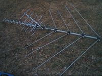
- The isotropic radiatorIsotropic radiatorAn isotropic radiator is a theoretical point source of electromagnetic or sound waves which radiates the same intensity of radiation in all directions. It has no preferred direction of radiation. It radiates uniformly in all directions over a sphere centred on the source...
is a purely theoretical antenna that radiates equally in all directions. It is considered to be a point in space with no dimensions and no mass. This antenna cannot physically exist, but is useful as a theoretical model for comparison with all other antennas. Most antennas' gains are measured with reference to an isotropic radiator, and are rated in dBi (decibels with respect to an isotropic radiator). - The dipole antennaDipole antennaA dipole antenna is a radio antenna that can be made of a simple wire, with a center-fed driven element. It consists of two metal conductors of rod or wire, oriented parallel and collinear with each other , with a small space between them. The radio frequency voltage is applied to the antenna at...
is simply two wires pointed in opposite directions arranged either horizontally or vertically, with one end of each wire connected to the radio and the other end hanging free in space. Since this is the simplest practical antenna, it is also used as a reference modelReference antennaA reference antenna is an antenna with known performance. It is normally used to calibrate other systems.Reference antennas are built with particular care taken to make them simple, robust and repeatable. In a common usage scenario a reference antenna would be used as a transfer standard. First...
for other antennas; gain with respect to a dipole is labeled as dBd. Generally, the dipole is considered to be omnidirectionalOmnidirectional antennaIn radio communication, an omnidirectional antenna is an antenna which radiates radio wave power uniformly in all directions in one plane, with the radiated power decreasing with elevation angle above or below the plane, dropping to zero on the antenna's axis. This radiation pattern is often...
in the plane perpendicular to the axis of the antenna, but it has deep nullNull (radio)In radio electronics, a null is an area or vector in an antenna's radiation pattern where the signal cancels out almost entirely.This can be an advantage, as nulls in the horizontal plane can be used to protect other transmitters from interference. If not carefully planned however, nulls can...
s in the directions of the axis. Variations of the dipole include the folded dipole, the half wave antenna, the ground plane antenna, the whipWhip antennaA whip antenna is an antenna consisting of a single straight flexible wire or rod, often mounted above some type of conducting surface called a ground plane. The bottom end of the whip is connected to the radio receiver or transmitter. They are designed to be flexible so that they won't break...
, and the J-pole. - The Yagi-Uda antenna is a directional variation of the dipole with parasitic elements added which are functionality similar to adding a reflector and lenses (directors) to focus a filament light bulb.
- The random wire antennaRandom wire antennaA random wire antenna is a radio frequency antenna consisting of a wire whose length does not bear a relation to the wavelength of the radio waves used, but is typically chosen more for convenience. This type of antenna sometimes is called the zig-zag antenna, as it may be strung back and forth...
is simply a very long (at least one quarter wavelength) wire with one end connected to the radio and the other in free space, arranged in any way most convenient for the space available. Folding will reduce effectiveness and make theoretical analysis extremely difficult. (The added length helps more than the folding typically hurts.) Typically, a random wire antenna will also require an antenna tunerAntenna tunerAn antenna tuner, transmatch or antenna tuning unit is a device connected between a radio transmitter or receiver and its antenna to improve the efficiency of the power transfer between them by matching the impedance of the equipment to the antenna...
, as it might have a random impedance that varies non-linearly with frequency. - The horn antennaHorn antennaA horn antenna or microwave horn is an antenna that consists of a flaring metal waveguide shaped like a horn to direct the radio waves. Horns are widely used as antennas at UHF and microwave frequencies, above 300 MHz...
is used where high gain is needed, the wavelength is short (microwaveMicrowaveMicrowaves, a subset of radio waves, have wavelengths ranging from as long as one meter to as short as one millimeter, or equivalently, with frequencies between 300 MHz and 300 GHz. This broad definition includes both UHF and EHF , and various sources use different boundaries...
) and space is not an issue. Horns can be narrow band or wide band, depending on their shape. A horn can be built for any frequency, but horns for lower frequencies are typically impractical. Horns are also frequently used as reference antennaReference antennaA reference antenna is an antenna with known performance. It is normally used to calibrate other systems.Reference antennas are built with particular care taken to make them simple, robust and repeatable. In a common usage scenario a reference antenna would be used as a transfer standard. First...
s. - The parabolic antennaParabolic antennaA parabolic antenna is an antenna that uses a parabolic reflector, a curved surface with the cross-sectional shape of a parabola, to direct the radio waves. The most common form is shaped like a dish and is popularly called a dish antenna or parabolic dish...
consists of an active element at the focus of a parabolic reflectorParabolic reflectorA parabolic reflector is a reflective device used to collect or project energy such as light, sound, or radio waves. Its shape is that of a circular paraboloid, that is, the surface generated by a parabola revolving around its axis...
to reflect the waves into a plane wave. Like the horn it is used for high gain, microwave applications, such as satellite dishSatellite dishA satellite dish is a dish-shaped type of parabolic antenna designed to receive microwaves from communications satellites, which transmit data transmissions or broadcasts, such as satellite television.-Principle of operation:...
es. - The patch antennaPatch antennaA patch antenna is a type of radio antenna with a low profile, which can be mounted on a flat surface. It consists of a flat rectangular sheet or "patch" of metal, mounted over a larger sheet of metal called a ground plane. The assembly is usually contained inside a plastic radome, which...
consists mainly of a square conductor mounted over a groundplane. Another example of a planar antenna is the tapered slot antenna (TSA), as the Vivaldi-antennaVivaldi-antennaA Vivaldi-antenna is a co-planar broadband-antenna, which is made from a on both sides metalized dielectric plate.The feeding line excites a circular space via a microstrip line, terminated with a sector-shaped area....
.
Practical antennas
Although any circuit can radiate if driven with a signal of high enough frequency, most practical antennas are specially designed to radiate efficiently at a particular frequency. An example of an inefficient antenna is the simple Hertzian dipole antennaDipole antenna
A dipole antenna is a radio antenna that can be made of a simple wire, with a center-fed driven element. It consists of two metal conductors of rod or wire, oriented parallel and collinear with each other , with a small space between them. The radio frequency voltage is applied to the antenna at...
, which radiates over wide range of frequencies and is useful for its small size. A more efficient variation of this is the half-wave dipole, which radiates with high efficiency when the signal wavelength is twice the electrical length of the antenna.
One of the goals of antenna design is to minimize the reactance of the device so that it appears as a resistive load. An "antenna inherent reactance" includes not only the distributed reactance of the active antenna but also the natural reactance due to its location and surroundings (as for example, the capacity relation inherent in the position of the active antenna relative to ground). Reactance can be eliminated by operating the antenna at its resonant frequency, when its capacitive and inductive reactances are equal and opposite, resulting in a net zero reactive current. If this is not possible, compensating inductors or capacitors can instead be added to the antenna to cancel its reactance as far as the source is concerned.
Once the reactance has been eliminated, what remains is a pure resistance, which is the sum of two parts: the ohmic resistance of the conductors, and the radiation resistance
Radiation resistance
Radiation resistance is that part of an antenna's feedpoint resistance that is caused by the radiation of electromagnetic waves from the antenna. The radiation resistance is determined by the geometry of the antenna, not by the materials of which it is made...
. Power absorbed by the ohmic resistance becomes waste heat, and that absorbed by the radiation resistance becomes radiated electromagnetic energy. The greater the ratio of radiation resistance to ohmic resistance, the more efficient the antenna.
Effect of ground
Antennas are typically used in an environment where other objects are present that may have an effect on their performance. Height above ground has a very significant effect on the radiation pattern of some antenna types.At frequencies used in antennas, the ground behaves mainly as a dielectric
Dielectric
A dielectric is an electrical insulator that can be polarized by an applied electric field. When a dielectric is placed in an electric field, electric charges do not flow through the material, as in a conductor, but only slightly shift from their average equilibrium positions causing dielectric...
. The conductivity of ground at these frequencies is negligible. When an electromagnetic wave arrives at the surface of an object, two waves are created: one enters the dielectric and the other is reflected. If the object is a conductor, the transmitted wave is negligible and the reflected wave has almost the same amplitude as the incident one. When the object is a dielectric, the fraction reflected depends (among other things) on the angle of incidence
Angle of incidence
Angle of incidence is a measure of deviation of something from "straight on", for example:* in the approach of a ray to a surface, or* the angle at which the wing or horizontal tail of an airplane is installed on the fuselage, measured relative to the axis of the fuselage.-Optics:In geometric...
. When the angle of incidence is small (that is, the wave arrives almost perpendicularly) most of the energy traverses the surface and very little is reflected. When the angle of incidence is near 90° (grazing incidence) almost all the wave is reflected.
Most of the electromagnetic waves emitted by an antenna to the ground below the antenna at moderate (say < 60°) angles of incidence enter the earth and are absorbed (lost). But waves emitted to the ground at grazing angles, far from the antenna, are almost totally reflected. At grazing angles, the ground behaves as a mirror. Quality of reflection depends on the nature of the surface. When the irregularities of the surface are smaller than the wavelength, reflection is good.
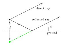
If the receiver is placed at some height above the ground, waves reflected by ground will travel a little longer distance to arrive to the receiver than direct waves. The distance will be the same only if the receiver is close to ground.
In the drawing at right, the angle has been drawn
 far bigger than in reality. The distance between the antenna and its image is
  .
.The situation is a bit more complex because the reflection of electromagnetic waves depends on the polarization of the incident wave. As the refractive index
Refractive index
In optics the refractive index or index of refraction of a substance or medium is a measure of the speed of light in that medium. It is expressed as a ratio of the speed of light in vacuum relative to that in the considered medium....
of the ground (average value
 ) is bigger than the refractive index of the air (
 ), the direction of the component of the electric field parallel to the ground inverses at the reflection. This is equivalent to a phase shift of
  radians or 180°. The vertical component of the electric field reflects without changing direction. This sign inversion of the parallel component and the non-inversion of the perpendicular component would also happen if the ground were a good electrical conductor.
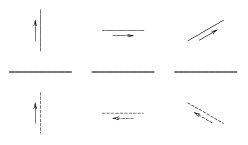
For a vertical polarized emission antenna the far electric field of the electromagnetic wave produced by the direct ray plus the reflected ray is:

The sign inversion for the parallel field case just changes a cosine to a sine:
-

In these two equations:-
 is the electrical field radiated by the antenna if there were no ground.
 -
 is the wave number.
 -
 is the wave length.
 -
 is the distance between antenna and its image (twice the height of the center of the antenna).
For emitting and receiving antennas situated near the ground (in a building or on a mast) far from each other, distances traveled by direct and reflected rays are nearly the same. There is no induced phase shift. If the emission is polarized vertically, the two fields (direct and reflected) add and there is maximum of received signal. If the emission is polarized horizontally, the two signals subtract and the received signal is minimum. This is depicted in the image at right. In the case of vertical polarization, there is always a maximum at earth level (left pattern). For horizontal polarization, there is always a minimum at earth level. Note that in these drawings the ground is considered as a perfect mirror, even for low angles of incidence. In these drawings, the distance between the antenna and its image is just a few wavelengths. For greater distances, the number of lobes increases.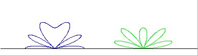
Note that the situation is different—and more complex—if reflections in the ionosphere occur. This happens over very long distances (thousands of kilometers). There is not a direct ray but several reflected rays that add with different phase shifts.
This is the reason why almost all public address radio emissions have vertical polarization. As public users are near ground, horizontal polarized emissions would be poorly received. Observe household and automobile radio receivers. They all have vertical antennas or horizontal ferrite antennas for vertical polarized emissions. In cases where the receiving antenna must work in any position, as in mobile phoneMobile phoneA mobile phone is a device which can make and receive telephone calls over a radio link whilst moving around a wide geographic area. It does so by connecting to a cellular network provided by a mobile network operator...
s, the emitter and receivers in base stations use circular polarizedCircular polarizationIn electrodynamics, circular polarization of an electromagnetic wave is a polarization in which the electric field of the passing wave does not change strength but only changes direction in a rotary type manner....
electromagnetic waves.
Classical (analog) television emissions are an exception. They are almost always horizontally polarized, because the presence of buildings makes it unlikely that a good emitter antenna image will appear. However, these same buildings reflect the electromagnetic waves and can create ghost imagesGhosting (television)In television, a ghost is a replica of the transmitted image, offset in position, that is super-imposed on top of the main image on an analogue broadcast.-Common causes:Common causes of ghosts are:...
. Using horizontal polarization, reflections are attenuated because of the low reflection of electromagnetic waves whose magnetic field is parallel to the dielectric surface near the Brewster's angleBrewster's angleBrewster's angle is an angle of incidence at which light with a particular polarization is perfectly transmitted through a transparent dielectric surface, with no reflection. When unpolarized light is incident at this angle, the light that is reflected from the surface is therefore perfectly...
. Vertically polarized analog television has been used in some rural areas.
In digital terrestrial televisionDigital terrestrial televisionDigital terrestrial television is the technological evolution of broadcast television and advance from analog television, which broadcasts land-based signals...
reflections are less obtrusive, due to the inherent robustness of digital signalDigital signalA digital signal is a physical signal that is a representation of a sequence of discrete values , for example of an arbitrary bit stream, or of a digitized analog signal...
ling and built-in error correctionError detection and correctionIn information theory and coding theory with applications in computer science and telecommunication, error detection and correction or error control are techniques that enable reliable delivery of digital data over unreliable communication channels...
.
Mutual impedance and interaction between antennas
Current circulating in any antenna induces currents in all others. One can postulate a mutual impedance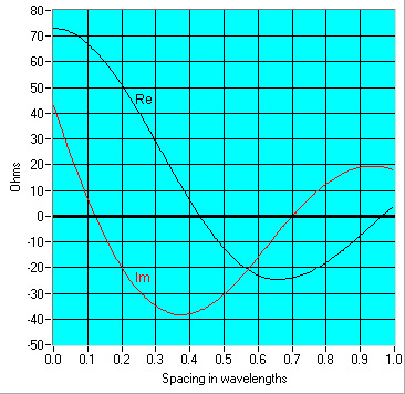
 between two antennas that has the same significance as the
  in ordinary coupled inductors. The mutual impedance
  between two antennas is defined as:
where is the current flowing in antenna 1 and
  is the voltage that would have to be applied to antenna 2–with antenna 1 removed–to produce the current in the antenna 2 that was produced by antenna 1.
From this definition, the currents and voltages applied in a set of coupled antennas are: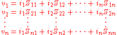
where:-
 is the voltage applied to the antenna
-
 is the impedance of antenna
-
 is the mutual impedance between antennas
  and
and 
Note that, as is the case for mutual inductances,
This is a consequence of Lorentz reciprocity. If some of the elements are not fed (there is a short circuit instead a feeder cable), as is the case in television antennas (Yagi-Uda antennasYagi antennaA Yagi-Uda array, commonly known simply as a Yagi antenna, is a directional antenna consisting of a driven element and additional parasitic elements...
), the corresponding are zero. Those elements are called parasitic elements. Parasitic elements are unpowered elements that either reflect or absorb and reradiate RF energy.
In some geometrical settings, the mutual impedance between antennas can be zero. This is the case for crossed dipoles used in circular polarization antennas.
See also
- Amateur radioAmateur radioAmateur radio is the use of designated radio frequency spectrum for purposes of private recreation, non-commercial exchange of messages, wireless experimentation, self-training, and emergency communication...
- Antenna measurementAntenna measurementAntenna measurement techniques refers to the testing of antennas to ensure that the antenna meets specifications or simply to characterize it. Typical parameters of antennas are gain, radiation pattern, beamwidth, polarization, and impedance....
- AWX antennaAWX antennaAn AWX antenna is an antenna which means that it can be used for All Wave radio frequency and is shaped like X.It has two "V" shaped elements. Two types to place these two elements exist for this antenna. First, one element is placed left side spreading out for left and the other element is placed...
:Category:Radio frequency antenna types
:Category:Radio frequency propagation- Cellular repeaterCellular repeaterA cellular repeater, cell phone repeater, or wireless cellular signal booster, a type of bi-directional amplifier as commonly named in the wireless telecommunications industry, is a device used for boosting the cell phone reception to the local area by the usage of a reception antenna, a signal...
- DXingDXingDXing is the hobby of tuning in and identifying distant radio or television signals, or making two way radio contact with distant stations in amateur radio, citizens' band radio or other two way radio communications. Many DXers also attempt to receive written verifications of reception from the...
- ElectromagnetismElectromagnetismElectromagnetism is one of the four fundamental interactions in nature. The other three are the strong interaction, the weak interaction and gravitation...
- Mast radiatorMast radiatorA mast radiator is a radio mast or tower in which the whole structure itself functions as an antenna. This design is commonly used for transmitting antennas operating at low frequencies, in the VLF, LF and MF ranges, in particular those used for AM broadcasting. The metal mast is electrically...
- Mobile modem
- Numerical Electromagnetics CodeNumerical Electromagnetics CodeThe Numerical Electromagnetics Code is a popular antenna modeling software package for wire and surface antennas. It is credited to Gerald J. Burke and Andrew J. Poggio, and was originally written in FORTRAN in the 1970s...
- Radio masts and towersRadio masts and towersRadio masts and towers are, typically, tall structures designed to support antennas for telecommunications and broadcasting, including television. They are among the tallest man-made structures...
- Radio telescopeRadio telescopeA radio telescope is a form of directional radio antenna used in radio astronomy. The same types of antennas are also used in tracking and collecting data from satellites and space probes...
- RF connectorRF connectorA coaxial RF connector is an electrical connector designed to work at radio frequencies in the multi-megahertz range.RF connectors are typically used with coaxial cables and are designed to maintain the shielding that the coaxial design offers. Better models also minimize the change in transmission...
- Satellite televisionSatellite televisionSatellite television is television programming delivered by the means of communications satellite and received by an outdoor antenna, usually a parabolic mirror generally referred to as a satellite dish, and as far as household usage is concerned, a satellite receiver either in the form of an...
- Smart antennaSmart antennaSmart antennas are antenna arrays with smart signal processing algorithms used to identify spatial signal signature such as the direction of arrival of the signal, and use it to calculate beamforming vectors, to track and locate the antenna beam on the mobile/target...
- Television antennaTelevision antennaA television antenna, or TV aerial, is an antenna specifically designed for the reception of over the air broadcast television signals, which are transmitted at frequencies from about 41 to 250 MHz in the VHF band, and 470 to 960 MHz in the UHF band in different countries...
- TETRATerrestrial Trunked RadioTerrestrial Trunked Radio is a professional mobile radio and two-way transceiver specification...
- Whip antennaWhip antennaA whip antenna is an antenna consisting of a single straight flexible wire or rod, often mounted above some type of conducting surface called a ground plane. The bottom end of the whip is connected to the radio receiver or transmitter. They are designed to be flexible so that they won't break...
- Wi-FiWi-FiWi-Fi or Wifi, is a mechanism for wirelessly connecting electronic devices. A device enabled with Wi-Fi, such as a personal computer, video game console, smartphone, or digital audio player, can connect to the Internet via a wireless network access point. An access point has a range of about 20...
General references
- Antenna Theory (3rd edition), by C. Balanis, Wiley, 2005, ISBN 0-471-66782-X;
- Antenna Theory and Design (2nd edition), by W. Stutzman and G. Thiele, Wiley, 1997, ISBN 0-471-02590-9;
- Antennas (3rd edition), by J. Kraus and R. Marhefka, McGraw-Hill, 2001, ISBN 0-072-32103-2;
- Antennenbuch, by Karl Rothammel, publ. Franck'sche Verlagshandlung Stuttgart, 1991, ISBN 3-440-05853-0; other editions (in German)
- Antennas for portable Devices, Zhi Ning Chen (edited), John Wiley & Sons in March 2007
- Broadband Planar Antennas: Design and Applications, Zhi Ning Chen and M. Y. W. Chia, John Wiley & Sons in February 2006
- The ARRL Antenna Book (15th edition), ARRL, 1988, ISBN 0-87259-207-5
"Practical antenna" references
- Antenna Theory antenna-theory.com
- Patch Antenna: From Simulation to Realization EM Talk
- Why an Antenna Radiates at ARRL
- Why Antennas Radiate, Stuart G. Downs, WY6EE (PDF)
- Understanding electromagnetic fields and antenna radiation takes (almost) no math, Ron Schmitt, EDN Magazine, March 2 2000 (PDF)
- Tests of FM/VHF receiving antennas.
- http://www.tvantennasperth.com.au/Diyantennas.html :"Antenna Gain"
- Antennas: Generalities, Principle of operation, As electronic component, Hertz Marconi and Other types Antennas etc etc
Theory and simulations
- http://www.dipoleanimator.com
- EM Talk, "Microstrip Patch Antenna", (Theory and simulation of microstrip patch antenna)
- "Online Calculations and Conversions " Formulas for simulating and optimizing Antenna specs and placement
- "Microwave Antenna Design Calculator" Provides quick estimation of antenna size required for a given gain and frequency. 3 dB and 10 dB beamwidths are also derived; the calculator additionally gives the far-field range required for a given antenna.
- Sophocles J. Orfanidis, "Electromagnetic Waves and Antennas", Rutgers University (20 PDF Chaps. Basic theory, definitions and reference)
- Hans Lohninger, "Learning by Simulations: Physics: Coupled Radiators". vias.org, 2005. (ed. Interactive simulation of two coupled antennas)
- NEC Lab - NEC Lab is a tool that uses Numerical Electromagnetics Code and Artificial Intelligence to design and simulate antennas.
- Justin Smith "Aerials". A.T.V (Aerials and Television), 2009. (ed. Article on the (basic) theory and use of FM, DAB & TV aerials)
- Antennas Research Group, "Virtual (Reality) Antennas". Democritus University of Thrace, 2005.
- "Support > Knowledgebase > RF Basics > Antennas / Cables > dBi vs. dBd detail". MaxStream, Inc., 2005. (ed. How to measure antenna gain)
- Yagis and Log Periodics, Astrosurf article.
- Raines, J. K., "Virtual Outer Conductor for Linear Antennas," Microwave Journal, Vol. 52, No. 1, January, 2009, pp. 76–86
- Tests of FM/VHF receiving antennas.
Effect of ground references- Electronic Radio and Engineering. F.E. Terman. McGraw-Hill
- Lectures on physics. Feynman, Leighton and Sands. Addison-Wesley
- Classical Electricity and Magnetism. W. Panofsky and M. Phillips. Addison-Wesley
Patents and USPTO
- CLASS 343, Communication: Radio Wave Antenna
Further reading
- Antennas for Base Stations in Wireless Communications, edited by Zhi Ning Chen and Kwai-Man Luk, McGraw-Hill Companies, Inc, USA in May 2009
-

