
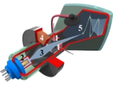
Oscilloscope
Encyclopedia

Voltage
Voltage, otherwise known as electrical potential difference or electric tension is the difference in electric potential between two points — or the difference in electric potential energy per unit charge between two points...
s, usually as a two-dimensional graph of one or more electrical potential differences using the vertical or 'Y' axis, plotted as a function of time, (horizontal or 'x' axis). Although an oscilloscope displays voltage on its vertical axis, any other quantity that can be converted to a voltage can be displayed as well. In most instances, oscilloscopes show events that repeat with either no change, or change slowly.
Oscilloscopes are commonly used to observe the exact wave shape
Waveform
Waveform means the shape and form of a signal such as a wave moving in a physical medium or an abstract representation.In many cases the medium in which the wave is being propagated does not permit a direct visual image of the form. In these cases, the term 'waveform' refers to the shape of a graph...
of an electrical signal. In addition to the amplitude of the signal, an oscilloscope can show distortion, the time between two events (such as pulse width, period, or rise time) and relative timing of two related signals.
Oscilloscopes are used in the sciences, medicine, engineering, and telecommunications industry. General-purpose instruments are used for maintenance of electronic equipment and laboratory work. Special-purpose oscilloscopes may be used for such purposes as analyzing an automotive ignition system, or to display the waveform of the heartbeat as an electrocardiogram
Electrocardiogram
Electrocardiography is a transthoracic interpretation of the electrical activity of the heart over a period of time, as detected by electrodes attached to the outer surface of the skin and recorded by a device external to the body...
.
Originally all oscilloscopes used cathode ray tube
Cathode ray tube
The cathode ray tube is a vacuum tube containing an electron gun and a fluorescent screen used to view images. It has a means to accelerate and deflect the electron beam onto the fluorescent screen to create the images. The image may represent electrical waveforms , pictures , radar targets and...
s as their display element and linear amplifiers for signal processing, (commonly referred to as CROs) however, modern oscilloscopes have LCD or LED screens, fast analog-to-digital converter
Analog-to-digital converter
An analog-to-digital converter is a device that converts a continuous quantity to a discrete time digital representation. An ADC may also provide an isolated measurement...
s and digital signal processors. Although not as commonplace, some oscilloscopes used storage CRTs to display single events for a limited time. Oscilloscope peripheral modules for general purpose laptop or desktop personal computer
Personal computer
A personal computer is any general-purpose computer whose size, capabilities, and original sales price make it useful for individuals, and which is intended to be operated directly by an end-user with no intervening computer operator...
s use the computer's display, allowing them to be used as test instruments.
Features and uses
Display and general external appearance
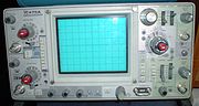
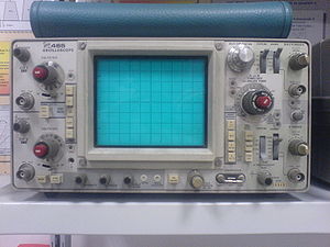
The basic oscilloscope, as shown in the illustration, is typically divided into four sections: the display, vertical controls, horizontal controls and trigger controls. The display is usually a CRT or LCD panel which is laid out with both horizontal and vertical reference lines referred to as the graticule. In addition to the screen, most display sections are equipped with three basic controls, a focus knob, an intensity knob and a beam finder button.The vertical section controls the amplitude of the displayed signal. This section carries a Volts-per-Division (Volts/Div) selector knob, an AC/DC/Ground selector switch and the vertical (primary) input for the instrument. Additionally, this section is typically equipped with the vertical beam position knob.
The horizontal section controls the time base or “sweep” of the instrument. The primary control is the Seconds-per-Division (Sec/Div) selector switch. Also included is a horizontal input for plotting dual X-Y axis signals. The horizontal beam position knob is generally located in this section.
The trigger section controls the start event of the sweep. The trigger can be set to automatically restart after each sweep or it can be configured to respond to an internal or external event. The principal controls of this section will be the source and coupling selector switches. An external trigger input (EXT Input) and level adjustment will also be included.
In addition to the basic instrument, most oscilloscopes are supplied with a probe as shown. The probe will connect to any input on the instrument and typically has a resistor of ten times the oscilloscope's input impedance. This results in a .1 (-10X) attenuation factor, but helps to isolate the capacitive load presented by the probe cable from the signal being measured. Some probes have a switch allowing the operator to bypass the resistor when appropriate.
Size and portability
Most modern oscilloscopes are lightweight, portable instruments that are compact enough to be easily carried by a single person. In addition to the portable units, the market offers a number of miniature battery-powered instruments for field service applications. Laboratory grade oscilloscopes, especially older units which use vacuum tubeVacuum tube
In electronics, a vacuum tube, electron tube , or thermionic valve , reduced to simply "tube" or "valve" in everyday parlance, is a device that relies on the flow of electric current through a vacuum...
s, are generally bench-top devices or may be mounted into dedicated carts. Special-purpose oscilloscopes may be rack-mounted or permanently mounted into a custom instrument housing.
Inputs
The signal to be measured is fed to one of the input connectors, which is usually a coaxial connector such as a BNCBNC connector
The BNC connector ' is a common type of RF connector used for coaxial cable. It is used with radio, television, and other radio-frequency electronic equipment, test instruments, video signals, and was once a popular computer network connector. BNC connectors are made to match the characteristic...
or UHF type
UHF connector
The UHF connector, also called the Amphenol coaxial connector,is a World War II threaded RF connector design, from an era whenUHF referred to frequencies over 30 MHz.Originally intended for use as a video connector in RADAR applications,...
. Binding post
Binding post
A binding post is a connector commonly used on electronic test equipment to terminate a single wire or test lead. They are also found on loudspeakers and audio amplifiers as well as other electrical equipment....
s or banana plugs may be used for lower frequencies.
If the signal source has its own coaxial connector, then a simple coaxial cable
Coaxial cable
Coaxial cable, or coax, has an inner conductor surrounded by a flexible, tubular insulating layer, surrounded by a tubular conducting shield. The term coaxial comes from the inner conductor and the outer shield sharing the same geometric axis...
is used; otherwise, a specialised cable called a "scope probe
Test probe
A test probe is a physical device used to connect electronic test equipment to the device under test . They range from very simple, rugged devices to complex probes that are sophisticated, expensive, and fragile.- Voltage probes :Voltage probes are intended to measure voltages on the DUT...
", supplied with the oscilloscope, is used. In general, for routine use, an open wire test lead for connecting to the point being observed is not satisfactory, and a probe is generally necessary.
General-purpose oscilloscopes usually present an input impedance of 1 megohm
Ohm
The ohm is the SI unit of electrical resistance, named after German physicist Georg Simon Ohm.- Definition :The ohm is defined as a resistance between two points of a conductor when a constant potential difference of 1 volt, applied to these points, produces in the conductor a current of 1 ampere,...
in parallel with a small but known capacitance such as 20 picofarads. This allows the use of standard oscilloscope probes. Scopes for use with very high frequencies may have 50-ohm inputs, which must be either connected directly to a 50-ohm signal source or used with Z0 or active probes.
Less-frequently-used inputs include one (or two) for triggering the sweep, horizontal deflection for X-Y mode displays, and trace brightening/darkening, sometimes called "Z-axis" inputs.
Probes
Open wire test leads (flying leads) are likely to pick up interference, so they are not suitable for low level signals. Furthermore, the leads have a high inductance, so they are not suitable for high frequencies. Using a shielded cable (i.e., coaxial cable) is better for low level signals. Coaxial cable also has lower inductance, but it has higher capacitance: a typical 50 ohm cable has about 90 pF per meter. Consequently, a one meter direct (1X) coaxial probe will load a circuit with a capacitance of about 110 pF and a resistance of 1 megohm.To minimize loading, attenuator probes (e.g., 10X probes) are used. A typical probe uses a 9 megohm series resistor shunted by a low-value capacitor to make an RC compensated divider with the cable capacitance and scope input. The RC time constants are adjusted to match. For example, the 9 megohm series resistor is shunted by a 12.2 pF capacitor for a time constant of 110 microseconds. The cable capacitance of 90 pF in parallel with the scope input of 20 pF and 1 megohm (total capacitance 110 pF) also gives a time constant of 110 microseconds. In practice, there will be an adjustment so the operator can precisely match the low frequency time constant (called compensating the probe). Matching the time constants makes the attenuation independent of frequency. At low frequencies (where the resistance of R is much less than the reactance of C), the circuit looks like a resistive divider; at high frequencies (resistance much greater than reactance), the circuit looks like a capacitive divider.
The result is a frequency compensated probe for modest frequencies that presents a load of about 10 megohms shunted by 12 pF. Although such a probe is an improvement, it does not work when the time scale shrinks to several cable transit times (transit time is typically 5 ns). In that time frame, the cable looks like its characteristic impedance, and there will be reflections from the transmission line mismatch at the scope input and the probe that causes ringing. The modern scope probe uses lossy low capacitance transmission lines and sophisticated frequency shaping networks to make the 10X probe perform well at several hundred megahertz. Consequently, there are other adjustments for completing the compensation.
Probes with 10:1 attenuation are by far the most common; for large signals (and slightly-less capacitive loading), 100:1 probes are not rare. There are also probes that contain switches to select 10:1 or direct (1:1) ratios, but one must be aware that the 1:1 setting has significant capacitance (tens of pF) at the probe tip, because the whole cable's capacitance is now directly connected.
Good oscilloscopes allow for probe attenuation, easily showing effective sensitivity at the probe tip. Some of the best ones have indicator lamps behind translucent windows in the panel to prompt the user to read effective sensitivity. The probe connectors (modified BNCs
BNC connector
The BNC connector ' is a common type of RF connector used for coaxial cable. It is used with radio, television, and other radio-frequency electronic equipment, test instruments, video signals, and was once a popular computer network connector. BNC connectors are made to match the characteristic...
) have an extra contact to define the probe's attenuation. (A certain value of resistor, connected to ground, "encodes" the attenuation.)
There are special high-voltage probes which also form compensated attenuators with the oscilloscope input; the probe body is physically large, and one made by Tektronix requires partly filling a canister surrounding the series resistor with volatile liquid fluorocarbon to displace air. At the oscilloscope end is a box with several waveform-trimming adjustments. For safety, a barrier disc keeps one's fingers distant from the point being examined. Maximum voltage is in the low tens of kV. (Observing a high-voltage ramp can create a staircase waveform with steps at different points every repetition, until the probe tip is in contact. Until then, a tiny arc charges the probe tip, and its capacitance holds the voltage (open circuit). As the voltage continues to climb, another tiny arc charges the tip further.)
There are also current probes, with cores that surround the conductor carrying current to be examined. One type has a hole for the conductor, and requires that the wire be passed through the hole; it's for semi-permanent or permanent mounting. However, other types, for testing, have a two-part core that permit them to be placed around a wire. Inside the probe, a coil wound around the core provides a current into an appropriate load, and the voltage across that load is proportional to current. However, this type of probe can sense AC, only.
A more-sophisticated probe (originally made by Tektronix) includes a magnetic flux sensor (Hall effect
Hall effect
The Hall effect is the production of a voltage difference across an electrical conductor, transverse to an electric current in the conductor and a magnetic field perpendicular to the current...
sensor) in the magnetic circuit. The probe connects to an amplifier, which feeds (low frequency) current into the coil to cancel the sensed field; the magnitude of that current provides the low-frequency part of the current waveform, right down to DC. The coil still picks up high frequencies. There is a combining network akin to a loudspeaker crossover network.
Focus control
This control adjusts CRT focus to obtain the sharpest, most-detailed trace. In practice, focus needs to be adjusted slightly when observing quite-different signals, which means that it needs to be an external control. Flat-panel displays do not need focus adjustments and therefore do not include this control.Intensity control
This adjusts trace brightness. Slow traces on CRT oscilloscopes need less, and fast ones, especially if not often repeated, require more. On flat panels, however, trace brightness is essentially independent of sweep speed, because the internal signal processing effectively synthesizes the display from the digitized data.Astigmatism
Can also be called "Shape" or "spot shape". Adjusts the relative voltages on two of the CRT anodes such that a displayed spot changes from elliptical in one plane through a circular spot to an elipse at 90 degrees to the first. This control may be absent from simpler oscilloscope designs or may even be an internal control. It is not necessary with flat panel displays.Beam finder
Modern oscilloscopes have direct-coupled deflection amplifiers, which means the trace could be deflected off-screen. They also might have their CRT beam blanked without the operator knowing it. In such cases, the screen is blank. To help in restoring the display quickly and without experimentation, the beam finder circuit overrides any blanking and ensures that the beam will not be deflected off-screen; it limits the deflection. With a display, it's usually very easy to restore a normal display. (While active, beam-finder circuits might temporarily distort the trace severely, however this is acceptable.)Graticule
The graticule is a grid of squares that serve as reference marks for measuring the displayed trace. These markings, whether located directly on the screen or on a removable plastic filter, usually consist of a 1 cm grid with closer tick marks (often at 2 mm) on the centre vertical and horizontal axis. One expects to see ten major divisions across the screen; the number of vertical major divisions varies. Comparing the grid markings with the waveform permits one to measure both voltage (vertical axis) and time (horizontal axis). Frequency can also be determined by measuring the waveform period and calculating its reciprocal.On old and lower-cost CRT oscilloscopes the graticule is a sheet of plastic, often with light-diffusing markings and concealed lamps at the edge of the graticule. The lamps had a brightness control. Higher-cost instruments have the graticule marked on the inside face of the CRT, to eliminate parallax
Parallax
Parallax is a displacement or difference in the apparent position of an object viewed along two different lines of sight, and is measured by the angle or semi-angle of inclination between those two lines. The term is derived from the Greek παράλλαξις , meaning "alteration"...
errors; better ones also had adjustable edge illumination with diffusing markings. (Diffusing markings appear bright.) Digital oscilloscopes, however, generate the graticule markings on the display in the same way as the trace.
External graticules also protect the glass face of the CRT from accidental impact. Some CRT oscilloscopes with internal graticules have an unmarked tinted sheet plastic light filter to enhance trace contrast; this also serves to protect the faceplate of the CRT.
Accuracy and resolution of measurements using a graticule is relatively limited; better instruments sometimes have movable bright markers on the trace that permit internal circuits to make more refined measurements.
Both calibrated vertical sensitivity and calibrated horizontal time are set in 1 - 2 - 5 - 10 steps. This leads, however, to some awkward interpretations of minor divisions. At 2, each of the five minor divisions is 0.4, so one has to think 0.4, 0.8, 1.2, and 1.6, which is rather awkward. One Tektronix plug-in used a 1 - 2.5 - 5 - 10 sequence, which simplified estimating. The "2.5" didn't look as "neat", but was very welcome.
Timebase controls
These select the horizontal speed of the CRT's spot as it creates the trace; this process is commonly referred to as the sweep. In all but the least-costly modern oscilloscopes, the sweep speed is selectable and calibrated in units of time per major graticule division. Quite a wide range of sweep speeds is generally provided, from seconds to as fast as picoseconds (in the fastest) per division. Usually, a continuously-variable control (often a knob in front of the calibrated selector knob) offers uncalibrated speeds, typically slower than calibrated. This control provides a range somewhat greater than that of consecutive calibrated steps, making any speed available between the extremes.Holdoff control
Found on some better analog oscilloscopes, this varies the time (holdoff) during which the sweep circuit ignores triggers. It provides a stable display of some repetitive events in which some triggers would create confusing displays. It is usually set to minimum, because a longer time decreases the number of sweeps per second, resulting in a dimmer trace. See trigger holdoff for a more detailed description.Vertical sensitivity, coupling, and polarity controls
To accommodate a wide range of input amplitudes, a switch selects calibrated sensitivity of the vertical deflection. Another control, often in front of the calibrated-selector knob, offers a continuously-variable sensitivity over a limited range from calibrated to less-sensitive settings.Often the observed signal is offset by a steady component, and only the changes are of interest. A switch (AC position) connects a capacitor in series with the input that passes only the changes (provided that they are not too slow -- "slow" would mean visible). However, when the signal has a fixed offset of interest, or changes quite slowly, the input is connected directly (DC switch position). Most oscilloscopes offer the DC input option. For convenience, to see where zero volts input currently shows on the screen, many oscilloscopes have a third switch position (GND) that disconnects the input and grounds it. Often, in this case, the user centers the trace with the Vertical Position control.
Better oscilloscopes have a polarity selector. Normally, a positive input moves the trace upward, but this permits inverting—positive deflects the trace downward.
Horizontal sensitivity control
This control is found only on more elaborate oscilloscopes; it offers adjustable sensitivity for external horizontal inputs.Vertical position control
The vertical position control moves the whole displayed trace up and down. It is used to set the no-input trace exactly on the center line of the graticule, but also permits offsetting vertically by a limited amount. With direct coupling, adjustment of this control can compensate for a limited DC component of an input.Horizontal position control
The horizontal position control moves the display sidewise. It usually sets the left end of the trace at the left edge of the graticule, but it can displace the whole trace when desired. This control also moves the X-Y mode traces sidewise in some instruments, and can compensate for a limited DC component as for vertical position.Dual-trace controls
* (Please see Dual and Multiple-trace Oscilloscopes, below.)Each input channel usually has its own set of sensitivity, coupling, and position controls, although some four-trace oscilloscopes have only minimal controls for their third and fourth channels.
Dual-trace oscilloscopes have a mode switch to select either channel alone, both channels, or (in some) an X-Y display, which uses the second channel for X deflection. When both channels are displayed, the type of channel switching can be selected on some oscilloscopes; on others, the type depends upon timebase setting. If manually selectable, channel switching can be free-running (asynchronous), or between consecutive sweeps. Some Philips dual-trace analog oscilloscopes had a fast analog multiplier, and provided a display of the product of the input channels.
Multiple-trace oscilloscopes have a switch for each channel to enable or disable display of that trace's signal.
Delayed-sweep controls
* (Please see Delayed Sweep, below.)These include controls for the delayed-sweep timebase, which is calibrated, and often also variable. The slowest speed is several steps faster than the slowest main sweep speed, although the fastest is generally the same. A calibrated multiturn delay time control offers wide range, high resolution delay settings; it spans the full duration of the main sweep, and its reading corresponds to graticule divisions (but with much finer precision). Its accuracy is also superior to that of the display.
A switch selects display modes: Main sweep only, with a brightened region showing when the delayed sweep is advancing, delayed sweep only, or (on some) a combination mode.
Good CRT oscilloscopes include a delayed-sweep intensity control, to allow for the dimmer trace of a much-faster delayed sweep that nevertheless occurs only once per main sweep. Such oscilloscopes also are likely to have a trace separation control for multiplexed display of both the main and delayed sweeps together.
Sweep trigger controls
* (Please see Triggered Sweep, below.)A switch selects the Trigger Source. It can be an external input, one of the vertical channels of a dual or multiple-trace oscilloscope, or the AC line (mains) frequency. Another switch enables or disables Auto trigger mode, or selects single sweep, if provided in the oscilloscope. Either a spring-return switch position or a pushbutton arms single sweeps.
A Level control varies the voltage on the waveform which generates a trigger, and the Slope switch selects positive-going or negative-going polarity at the selected trigger level.
Triggered sweeps
A triggered sweep starts at a selected point on the signal, providing a stable display. In this way, triggering allows the display of periodic signals such as sine waves and square waves, as well as nonperiodic signals such as single pulses, or pulses that don't recur at a fixed rate.
With triggered sweeps, the scope will blank the beam and start to reset the sweep circuit each time the beam reaches the extreme right side of the screen. For a period of time, called holdoff, (extendable by a front-panel control on some better oscilloscopes), the sweep circuit resets completely and ignores triggers. Once holdoff expires, the next trigger starts a sweep. The trigger event is usually the input waveform reaching some user-specified threshold voltage (trigger level) in the specified direction (going positive or going negative—trigger polarity).
In some cases, variable holdoff time can be really useful to make the sweep ignore interfering triggers that occur before the events one wants to observe. In the case of repetitive, but quite-complex waveforms, variable holdoff can create a stable display that can't otherwise practically be obtained.
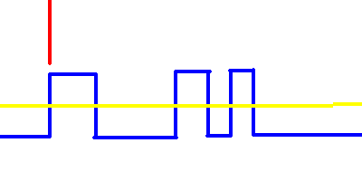
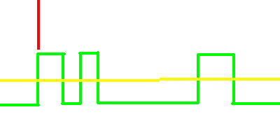
Holdoff
Trigger holdoff defines a certain period following a trigger during which the scope will not trigger again. This makes it easier to establish a stable view of a waveformWaveform
Waveform means the shape and form of a signal such as a wave moving in a physical medium or an abstract representation.In many cases the medium in which the wave is being propagated does not permit a direct visual image of the form. In these cases, the term 'waveform' refers to the shape of a graph...
with multiple edges which would otherwise cause another trigger.
Example
Imagine the following repeating waveform: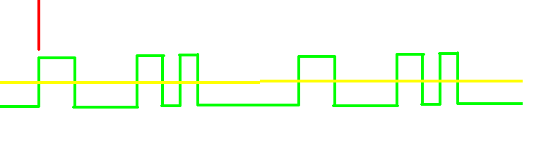
The greenline is the waveform, the red vertical partial line represents the location of the trigger, and the yellow line represents the trigger level. If the scope was simply set to trigger on every rising edge, this waveform would cause three triggers for each cycle:
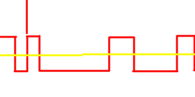
Assuming the signal is fairly high frequency
Frequency
Frequency is the number of occurrences of a repeating event per unit time. It is also referred to as temporal frequency.The period is the duration of one cycle in a repeating event, so the period is the reciprocal of the frequency...
, your scope would probably look something like this:
Except that on the scope, each trigger would be the same channel, and so would be the same color.
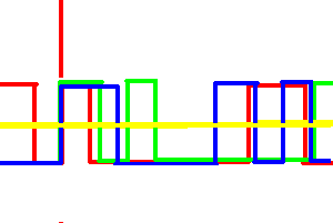
What we want to do is set the scope to only trigger on one edge per cycle, so we need to set the holdoff to be a little less than the period of the waveform. That will prevent if from triggering more than once per cycle, but still allow it to trigger on the first edge of the next cycle.
Automatic sweep mode
Triggered sweeps can display a blank screen if there are no triggers. To avoid this, these sweeps include a timing circuit that generates free-running triggers so a trace is always visible. Once triggers arrive, the timer stops providing pseudo-triggers. Automatic sweep mode can be de-selected when observing low repetition rates.
Recurrent sweeps
If the input signal is periodic, the sweep repetition rate can be adjusted to display a few cycles of the waveform. Early (tube) oscilloscopes and lowest-cost oscilloscopes have sweep oscillators that run continuously, and are uncalibrated. Such oscilloscopes are very simple, comparatively inexpensive, and were useful in radio servicing and some TV servicing. Measuring voltage or time is possible, but only with extra equipment, and is quite inconvenient. They are primarily qualitative instruments.They have a few (widely spaced) frequency ranges, and relatively wide-range continuous frequency control within a given range. In use, the sweep frequency is set to slightly lower than some submultiple of the input frequency, to display typically at least two cycles of the input signal (so all details are visible). A very simple control feeds an adjustable amount of the vertical signal (or possibly, a related external signal) to the sweep oscillator. The signal triggers beam blanking and a sweep retrace sooner than it would occur free-running, and the display becomes stable.
Single sweeps
Some oscilloscopes offer these—the sweep circuit is manually armed (typically by a pushbutton or equivalent) "Armed" means it's ready to respond to a trigger. Once the sweep is complete, it resets, and will not sweep until re-armed. This mode, combined with a oscilloscope camera, captures single-shot events.Types of trigger include:
- external trigger, a pulse from an external source connected to a dedicated input on the scope.
- edge trigger, an edge-detector that generates a pulse when the input signal crosses a specified threshold voltage in a specified direction. These are the most-common types of triggers; the level control sets the threshold voltage, and the slope control selects the direction (negative or positive-going). (The first sentence of the description also applies to the inputs to some digital logic circuits; those inputs have fixed threshold and polarity response.)
- video trigger, a circuit that extracts synchronizing pulses from videoVideoVideo is the technology of electronically capturing, recording, processing, storing, transmitting, and reconstructing a sequence of still images representing scenes in motion.- History :...
formats such as PALPALPAL, short for Phase Alternating Line, is an analogue television colour encoding system used in broadcast television systems in many countries. Other common analogue television systems are NTSC and SECAM. This page primarily discusses the PAL colour encoding system...
and NTSCNTSCNTSC, named for the National Television System Committee, is the analog television system that is used in most of North America, most of South America , Burma, South Korea, Taiwan, Japan, the Philippines, and some Pacific island nations and territories .Most countries using the NTSC standard, as...
and triggers the timebase on every line, a specified line, every field, or every frame. This circuit is typically found in a waveform monitorWaveform monitorA waveform monitor is a special type of oscilloscope used in television production applications. It is typically used to measure and display the level, or voltage, of a video signal with respect to time....
device, although some better oscilloscopes include this function. - delayed trigger, which waits a specified time after an edge trigger before starting the sweep. As described under delayed sweeps, a trigger delay circuit (typically the main sweep) extends this delay to a known and adjustable interval. In this way, the operator can examine a particular pulse in a long train of pulses.
Some recent designs of oscilloscopes include more sophisticated triggering schemes; these are described toward the end of this article.
Delayed sweeps
These are found on more-sophisticated oscilloscopes, which contain a second set of timebase circuits for a delayed sweep. A delayed sweep provides a very-detailed look at some small selected portion of the main timebase. The main timebase serves as a controllable delay, after which the delayed timebase starts. This can start when the delay expires, or can be triggered (only) after the delay expires. Ordinarily, the delayed timebase is set for a faster sweep, sometimes much faster, such as 1000:1. At extreme ratios, jitter in the delays on consecutive main sweeps degrades the display, but delayed-sweep triggers can overcome that.The display shows the vertical signal in one of several modes—the main timebase, or the delayed timebase only, or a combination. When the delayed sweep is active, the main sweep trace brightens while the delayed sweep is advancing. In one combination mode, provided only on some oscilloscopes, the trace changes from the main sweep to the delayed sweep once the delayed sweep starts, although less of the delayed fast sweep is visible for longer delays. Another combination mode multiplexes (alternates) the main and delayed sweeps so that both appear at once; a trace separation control displaces them.
Dual and multiple-trace oscilloscopes
Oscilloscopes with two vertical inputs, referred to as dual-trace oscilloscopes, are extremely useful and commonplace.Using a single-beam CRT, they multiplex
Multiplexing
The multiplexed signal is transmitted over a communication channel, which may be a physical transmission medium. The multiplexing divides the capacity of the low-level communication channel into several higher-level logical channels, one for each message signal or data stream to be transferred...
the inputs, usually switching between them fast enough to display two traces apparently at once. Less common are oscilloscopes with more traces; four inputs are common among these, but a few (Kikusui, for one) offered a display of the sweep trigger signal if desired. Some multi-trace oscilloscopes use the external trigger input as an optional vertical input, and some have third and fourth channels with only minimal controls. In all cases, the inputs, when independently displayed, are time-multiplexed, but dual-trace oscilloscopes often can add their inputs to display a real-time analog sum. (Inverting one channel provides a difference, provided that neither channel is overloaded. This difference mode can provide a moderate-performance differential input.)
Switching channels can be asynchronous, that is, free-running, with trace blanking while switching, or after each horizontal sweep is complete. Asynchronous switching is usually designated "Chopped", while sweep-synchronized is designated "Alt[ernate]". A given channel is alternately connected and disconnected, leading to the term "chopped". Multi-trace oscilloscopes also switch channels either in chopped or alternate modes.
In general, chopped mode is better for slower sweeps. It is possible for the internal chopping rate to be a multiple of the sweep repetition rate, creating blanks in the traces, but in practice this is rarely a problem; the gaps in one trace are overwritten by traces of the following sweep. A few oscilloscopes had a modulated chopping rate to avoid this occasional problem. Alternate mode, however, is better for faster sweeps.
True dual-beam CRT oscilloscopes did exist, but were not common. One type (Cossor, U.K.) had a beam-splitter plate in its CRT, and single-ended deflection following the splitter. (More details are near the end of this article; see "CRT Invention". Others had two complete electron guns, requiring tight control of axial (rotational) mechanical alignment in manufacturing the CRT. Beam-splitter types had horizontal deflection common to both vertical channels, but dual-gun oscilloscopes could have separate time bases, or use one time base for both channels. Multiple-gun CRTs (up to ten guns) were made in past decades. With ten guns, the envelope (bulb) was cylindrical throughout its length.
The vertical amplifier
In an analog oscilloscope, the vertical amplifier acquires the signal[s] to be displayed. In better oscilloscopes, it delays them by a fraction of a microsecond, and provides a signal large enough to deflect the CRT's beam. That deflection is at least somewhat beyond the edges of the graticule, and more typically some distance off-screen. The amplifier has to have low distortion to display its input accurately (it must be linear), and it has to recover quickly from overloads. As well, its time-domain response has to represent transients accurately—minimal overshoot, rounding, and tilt of a flat pulse top.A vertical input goes to a frequency-compensated step attenuator to reduce large signals to prevent overload. The attenuator feeds a low-level stage (or a few), which in turn feed gain stages (and a delay-line driver if there is a delay). Following are more gain stages, up to the final output stage which develops a large signal swing (tens of volts, sometimes over 100 volts) for CRT electrostatic deflection.
In dual and multiple-trace oscilloscopes, an internal electronic switch selects the relatively low-level output of one channel's amplifiers and sends it to the following stages of the vertical amplifier, which is only a single channel, so to speak, from that point on.
In free-running ("chopped") mode, the oscillator (which may be simply a different operating mode of the switch driver) blanks the beam before switching, and unblanks it only after the switching transients have settled.
Part way through the amplifier is a feed to the sweep trigger circuits, for internal triggering from the signal. This feed would be from an individual channel's amplifier in a dual or multi-trace oscilloscope, the channel depending upon the setting of the trigger source selector.
This feed precedes the delay (if there is one), which allows the sweep circuit to unblank the CRT and start the forward sweep, so the CRT can show the triggering event. High-quality analog delays add a modest cost to a oscilloscope, and are omitted in oscilloscopes that are cost-sensitive.
The delay, itself, comes from a special cable with a pair of conductors wound around a flexible magnetically-soft core. The coiling provides distributed inductance, while a conductive layer close to the wires provides distributed capacitance. The combination is a wideband transmission line with considerable delay per unit length. Both ends of the delay cable require matched impedances to avoid reflections.
X-Y mode
Most modern oscilloscopes have several inputs for voltages, and thus can be used to plot one varying voltage versus another. This is especially useful for graphing I-V curves (currentElectric current
Electric current is a flow of electric charge through a medium.This charge is typically carried by moving electrons in a conductor such as wire...
versus voltage
Voltage
Voltage, otherwise known as electrical potential difference or electric tension is the difference in electric potential between two points — or the difference in electric potential energy per unit charge between two points...
characteristics) for components such as diode
Diode
In electronics, a diode is a type of two-terminal electronic component with a nonlinear current–voltage characteristic. A semiconductor diode, the most common type today, is a crystalline piece of semiconductor material connected to two electrical terminals...
s, as well as Lissajous patterns
Lissajous curve
In mathematics, a Lissajous curve , also known as Lissajous figure or Bowditch curve, is the graph of a system of parametric equationswhich describe complex harmonic motion...
. Lissajous figures are an example of how an oscilloscope can be used to track phase
Phase (waves)
Phase in waves is the fraction of a wave cycle which has elapsed relative to an arbitrary point.-Formula:The phase of an oscillation or wave refers to a sinusoidal function such as the following:...
differences between multiple input signals. This is very frequently used in broadcast engineering
Broadcast engineering
Broadcast engineering is the field of electrical engineering, and now to some extent computer engineering and information technology, which deals with radio and television broadcasting...
to plot the left and right stereophonic channels, to ensure that the stereo generator is calibrated properly. Historically, stable Lissajous figures were used to show that two sine waves had a relatively simple frequency relationship, a numerically-small ratio. They also indicated phase difference between two sine waves of the same frequency.
Complete loss of signal in an X-Y display means that the CRT's beam strikes a small spot, which risks burning the phosphor. Older phosphors burned more easily. Some dedicated X-Y displays reduce beam current greatly, or blank the display entirely, if there are no inputs present.
Bandwidth
Bandwidth is a measure of the range of frequencies that can be displayed; it refers primarily to the vertical amplifier, although the horizontal deflection amplifier has to be fast enough to handle the fastest sweeps. The bandwidth of the oscilloscope is limited by the vertical amplifiers and the CRT (in analog instruments) or by the sampling rate of the analog to digital converter in digital instruments. The bandwidth is defined as the frequency at which the sensitivity is 0.707 of the sensitivity at lower frequency (a drop of 3 dBDecibel
The decibel is a logarithmic unit that indicates the ratio of a physical quantity relative to a specified or implied reference level. A ratio in decibels is ten times the logarithm to base 10 of the ratio of two power quantities...
). The rise time
Rise time
In electronics, when describing a voltage or current step function, rise time refers to the time required for a signal to change from a specified low value to a specified high value...
of the fastest pulse that can be resolved by the scope is related to its bandwidth approximately:
Bandwidth in Hz x rise time in seconds = 0.35
For example, a oscilloscope intended to resolve pulses with a rise time of 1 nanosecond would have a bandwidth of 350 MHz.
For a digital oscilloscope, a rule of thumb is that the continuous sampling rate should be ten times the highest frequency desired to resolve; for example a 20 megasample/second rate would be applicable for measuring signals up to about 2 megahertz.
Other features
Some oscilloscopes have cursors, which are lines that can be moved about the screen to measure the time interval between two points, or the difference between two voltages. A few older oscilloscopes simply brightened the trace at movable locations. These cursors are more accurate than visual estimates referring to graticule lines.Better quality general purpose oscilloscopes include a calibration signal for setting up the compensation of test probes; this is (often) a 1 kHz square-wave signal of a definite peak-to-peak voltage available at a test terminal on the front panel. Some better oscilloscopes also have a squared-off loop for checking and adjusting current probes.
Sometimes the event that the user wants to see may only happen occasionally.
To catch these events, some oscilloscopes, known as "storage scopes", preserve the most recent sweep on the screen. This was originally achieved by using a special CRT, a "storage tube
Storage tube
Mostly obsolete, a storage tube is a special monochromatic CRT whose screen has a kind of 'memory' : when a portion of the screen is illuminated by the CRT's electron gun, it stays lit until a screen erase command is given...
", which would retain the image of even a very brief event for a long time.
Some digital oscilloscopes can sweep at speeds as slow as once per hour, emulating a strip chart recorder
Chart recorder
A chart recorder is an electromechanical device that records an electrical or mechanical input trend onto a piece of paper . Chart recorders may record several inputs using different color pens and may record onto strip charts or circular charts...
.
That is, the signal scrolls across the screen from right to left. Most oscilloscopes with this facility switch from a sweep to a strip-chart mode at about one sweep per ten seconds. This is because otherwise, the scope looks broken: it's collecting data, but the dot cannot be seen.
In current oscilloscopes, digital signal sampling is more often used for all but the simplest models. Samples feed fast analog-to-digital converters, following which all signal processing (and storage) is digital.
Many oscilloscopes have different plug-in modules for different purposes, e.g., high-sensitivity amplifiers of relatively narrow bandwidth, differential amplifiers, amplifiers with four or more channels, sampling plugins for repetitive signals of very high frequency, and special-purpose plugins, including audio/ultrasonic spectrum analyzers, and stable-offset-voltage direct-coupled channels with relatively high gain.
Examples of use
.gif)
Troubleshooting
Troubleshooting is a form of problem solving, often applied to repair failed products or processes. It is a logical, systematic search for the source of a problem so that it can be solved, and so the product or process can be made operational again. Troubleshooting is needed to develop and...
malfunctioning electronic equipment. One of the advantages of a scope is that it can graphically show signals: where a voltmeter
Voltmeter
A voltmeter is an instrument used for measuring electrical potential difference between two points in an electric circuit. Analog voltmeters move a pointer across a scale in proportion to the voltage of the circuit; digital voltmeters give a numerical display of voltage by use of an analog to...
may show a totally unexpected voltage, a scope may reveal that the circuit is oscillating. In other cases the precise shape or timing of a pulse is important.
In a piece of electronic equipment, for example, the connections between stages (e.g. electronic mixer
Electronic mixer
An electronic mixer is a device that combines two or more electrical or electronic signals into one or two composite output signals. There are two basic circuits that both use the term mixer, but they are very different types of circuits: additive mixers and multiplying mixers...
s, electronic oscillator
Electronic oscillator
An electronic oscillator is an electronic circuit that produces a repetitive electronic signal, often a sine wave or a square wave. They are widely used in innumerable electronic devices...
s, amplifier
Amplifier
Generally, an amplifier or simply amp, is a device for increasing the power of a signal.In popular use, the term usually describes an electronic amplifier, in which the input "signal" is usually a voltage or a current. In audio applications, amplifiers drive the loudspeakers used in PA systems to...
s) may be 'probed' for the expected signal, using the scope as a simple signal tracer. If the expected signal is absent or incorrect, some preceding stage of the electronics is not operating correctly. Since most failures occur because of a single faulty component, each measurement can prove that half of the stages of a complex piece of equipment either work, or probably did not cause the fault.
Once the faulty stage is found, further probing can usually tell a skilled technician exactly which component has failed. Once the component is replaced, the unit can be restored to service, or at least the next fault can be isolated. This sort of troubleshooting is typical of radio and TV receivers, as well as audio amplifiers, but can apply to quite-different devices such as electronic motor drives.
Another use is to check newly designed circuitry. Very often a newly designed circuit will misbehave because of design errors, bad voltage levels, electrical noise etc. Digital electronics usually operate from a clock, so a dual-trace scope which shows both the clock signal and a test signal dependent upon the clock is useful. Storage scopes are helpful for "capturing" rare electronic events that cause defective operation.
Pictures of use
Selection
Oscilloscopes generally have a checklist of some set of the above features. The basic measure of virtue is the bandwidth of its vertical amplifiers. Typical scopes for general purpose use should have a bandwidth of at least 100 MHz, although much lower bandwidths are acceptable for audio-frequency applications.A useful sweep range is from one second to 100 nanoseconds, with triggering and delayed sweep.
The chief benefit of a quality oscilloscope is the quality of the trigger circuit.
If the trigger is unstable, the display will always be fuzzy.
The quality improves roughly as the frequency response and voltage stability of the trigger increase.
Analog oscilloscopes have been almost totally displaced by digital storage scopes except for the low bandwidth (< 60 MHz) segment of the market. Greatly increased sample rates have eliminated the display of incorrect signals, known as "aliasing", that was sometimes present in the first generation of digital scopes. The used test equipment market, particularly on-line auction venues, typically have a wide selection of older analog scopes available. However it is becoming more difficult to obtain replacement parts for these instruments and repair services are generally unavailable from the original manufacturer.
, a 350 MHz bandwidth (BW), 2.5 giga-samples per second (GS/s), dual-channel digital storage scope costs about US$7000 new. The current true real-time analog bandwidth record, , is held by the LeCroy Wavemaster 8 ZI series of oscilloscopes with a 45 GHz BW and a sample rate of 120 GSa/s. The current equivalent time sampling bandwidth record for sampling digital storage oscilloscopes, , is held by the LeCroy WaveExpert series with a 100 GHz bandwidth.
On the lowest end, an inexpensive hobby-grade single-channel DSO can now be purchased for under $90 as of June 2011. These often have limited bandwidth but fulfill the basic functions of an oscilloscope.
Software
Many oscilloscopes today provide one or more external interfaces to allow remote instrument controlInstrument control
Instrument control consists of connecting a desktop instrument to a computer and taking measurements.-History:In the late 1960s the first bus used for communication was developed by Hewlett-Packard and was called HP-IB...
by external software. These interfaces (or buses) include GPIB, Ethernet
Ethernet
Ethernet is a family of computer networking technologies for local area networks commercially introduced in 1980. Standardized in IEEE 802.3, Ethernet has largely replaced competing wired LAN technologies....
, serial port
Serial port
In computing, a serial port is a serial communication physical interface through which information transfers in or out one bit at a time...
, and USB.
Types and models
The following section is a brief summary of various types and models available. For a detailed discussion, refer to the other article.Cathode-ray oscilloscope (CRO)
.jpg)
Cathode ray tube
The cathode ray tube is a vacuum tube containing an electron gun and a fluorescent screen used to view images. It has a means to accelerate and deflect the electron beam onto the fluorescent screen to create the images. The image may represent electrical waveforms , pictures , radar targets and...
, a vertical amplifier
Amplifier
Generally, an amplifier or simply amp, is a device for increasing the power of a signal.In popular use, the term usually describes an electronic amplifier, in which the input "signal" is usually a voltage or a current. In audio applications, amplifiers drive the loudspeakers used in PA systems to...
, a timebase, a horizontal amplifier and a power supply. These are now called 'analog' scopes to distinguish them from the 'digital' scopes that became common in the 1990s and 2000s.
Analog scopes do not necessarily include a calibrated reference grid for size measurement of waves, and they may not display waves in the traditional sense of a line segment sweeping from left to right. Instead, they could be used for signal analysis by feeding a reference signal into one axis and the signal to measure into the other axis. For an oscillating reference and measurement signal, this results in a complex looping pattern referred to as a lissajous curve
Lissajous curve
In mathematics, a Lissajous curve , also known as Lissajous figure or Bowditch curve, is the graph of a system of parametric equationswhich describe complex harmonic motion...
. The shape of the curve can be interpreted to identify properties of the measurement signal in relation to the reference signal, and is useful across a wide range of oscillation frequencies.
Dual-beam oscilloscope
The dual-beam analog oscilloscope can display two signals simultaneously. A special dual-beam CRTCathode ray tube
The cathode ray tube is a vacuum tube containing an electron gun and a fluorescent screen used to view images. It has a means to accelerate and deflect the electron beam onto the fluorescent screen to create the images. The image may represent electrical waveforms , pictures , radar targets and...
generates and deflects two separate beams. Although multi-trace analog oscilloscopes can simulate a dual-beam display with chop and alternate sweeps, those features do not provide simultaneous displays. (Real time digital oscilloscopes offer the same benefits of a dual-beam oscilloscope, but they do not require a dual-beam display.)
Analog storage oscilloscope
Trace storage is an extra feature available on some analog scopes; they used direct-view storage CRTs. Storage allows the trace pattern that normally decays in a fraction of a second to remain on the screen for several minutes or longer. An electrical circuit can then be deliberately activated to store and erase the trace on the screen.Digital oscilloscopes
While analog devices make use of continually varying voltages, digital devices employ binary numbers which correspond to samples of the voltage. In the case of digital oscilloscopes, an analog-to-digital converter (ADC) is used to change the measured voltages into digital information.The digital storage oscilloscope, or DSO for short, is now the preferred type for most industrial applications, although simple analog CROs are still used by hobbyists. It replaces the unreliable storage method used in analog storage scopes with digital memory
Computer memory
In computing, memory refers to the physical devices used to store programs or data on a temporary or permanent basis for use in a computer or other digital electronic device. The term primary memory is used for the information in physical systems which are fast In computing, memory refers to the...
, which can store data as long as required without degradation. It also allows complex processing of the signal by high-speed digital signal processing
Digital signal processing
Digital signal processing is concerned with the representation of discrete time signals by a sequence of numbers or symbols and the processing of these signals. Digital signal processing and analog signal processing are subfields of signal processing...
circuits.
Digital sampling oscilloscopes operate on the same principle as analog sampling oscilloscopes and like their analog partners, are of great use when analyzing high frequency signals. That is, signals whose frequencies are higher than the oscilloscope's sampling rate.
A digital phosphor Oscilloscope (DPO) is a digital oscilloscope but instead of a CRT, it uses a digital flat panel display, usually a liquid crystal
Liquid crystal
Liquid crystals are a state of matter that have properties between those of a conventional liquid and those of a solid crystal. For instance, an LC may flow like a liquid, but its molecules may be oriented in a crystal-like way. There are many different types of LC phases, which can be...
panel. These are becoming the de facto digital oscillosope system. With the relentless march of technological progress: DPOs can offer significant enhancements over traditional oscilloscopes, such as different colour traces for different inputs or signal types or even parts of the displayed signal. Also a DPO can emulate long persistence phosphors in traditional CRT systems. Many designs can also provide near real time information on the displayed waveform such as amplitude (including average; peak; peak to peak; and RMS), repetition rate and even more complex functions such as fourier transforms.
Mixed-signal oscilloscopes
A mixed-signal oscilloscope (or MSO) has two kinds of inputs, a small number (typically two or four) of analog channels, and a larger number (typically sixteen) of digital channels.Mixed-domain oscilloscopes
A mixed-domain oscilloscope (or MDO) has three kinds of inputs, a small number (typically two or four) analog channels, a larger number (typically sixteen) digital channels, and one RF channel. It provides the ability to accurately time-correlate analog, digital, and RF signals with each other, and allows the user to see how the RF spectrum changes over time.Handheld oscilloscopes
Handheld oscilloscopes (also called scopemeters) are useful for many test and field service applications. Today, a hand held oscilloscope is usually a digital sampling oscilloscope, using a liquid crystalLiquid crystal
Liquid crystals are a state of matter that have properties between those of a conventional liquid and those of a solid crystal. For instance, an LC may flow like a liquid, but its molecules may be oriented in a crystal-like way. There are many different types of LC phases, which can be...
display.
PC-based oscilloscopes (PCO)
A new type of "oscilloscope" is emerging that consists of a specialized signal acquisition board (which can be an external USB or Parallel portParallel port
A parallel port is a type of interface found on computers for connecting various peripherals. In computing, a parallel port is a parallel communication physical interface. It is also known as a printer port or Centronics port...
device, or an internal add-on PCI or ISA
Industry Standard Architecture
Industry Standard Architecture is a computer bus standard for IBM PC compatible computers introduced with the IBM Personal Computer to support its Intel 8088 microprocessor's 8-bit external data bus and extended to 16 bits for the IBM Personal Computer/AT's Intel 80286 processor...
card).
Related instruments
A large number of instruments used in a variety of technical fields are really oscilloscopes with inputs, calibration, controls, display calibration, etc., specialized and optimized for a particular application. Examples of such oscilloscope-based instruments include waveform monitorWaveform monitor
A waveform monitor is a special type of oscilloscope used in television production applications. It is typically used to measure and display the level, or voltage, of a video signal with respect to time....
s for analyzing video levels in television productions and medical devices such as vital function monitors and electrocardiogram and electroencephalogram instruments. In automobile repair, an ignition analyzer is used to show the spark waveforms for each cylinder. All of these are essentially oscilloscopes, performing the basic task of showing the changes in one or more input signals over time in an X-Y display.
Other instruments convert the results of their measurements to a repetitive electrical signal, and incorporate an oscilloscope as a display element. Such complex measurement systems include spectrum analyzer
Spectrum analyzer
A spectrum analyzer measures the magnitude of an input signal versus frequency within the full frequency range of the instrument. The primary use is to measure the power of the spectrum of known and unknown signals...
s, transistor analyzers, and time domain reflectometers (TDRs). Unlike an oscilloscope, these instruments automatically generate stimulus or sweep a measurement parameter.
History
The BraunKarl Ferdinand Braun
Karl Ferdinand Braun was a German inventor, physicist and Nobel laureate in physics. Braun contributed significantly to the development of the radio and television technology: he shared with Guglielmo Marconi the 1909 Nobel Prize in Physics.-Biography:Braun was born in Fulda, Germany, and...
tube was known in 1897, and in 1899 Jonathan Zenneck
Jonathan Zenneck
Jonathan Adolf Wilhelm Zenneck was a physicist and electrical engineer. Zenneck was born in Ruppertshofen, Württemberg. Zenneck contributed to researches in radio circuit performance and to the scientific and educational contributions to the literature of the pioneer radio art...
equipped it with beam-forming plates and a magnetic field for sweeping the trace. Early cathode ray tubes had been applied experimentally to laboratory measurements as early as the 1920s, but suffered from poor stability of the vacuum and the cathode emitters. V. K. Zworykin described a permanently sealed, high-vacuum cathode ray tube with a thermionic emitter in 1931. This stable and reproducible component allowed General Radio
General Radio
General Radio Company was a broad-line manufacturer of electronic test equipment. Started in Cambridge, Massachusetts in 1915, the company moved to West Concord in the 1950s. There, it became a major player in the automatic test equipment business, manufacturing a line of testers for assembled...
to manufacture an oscilloscope that was usable outside a laboratory setting.
Use as props
In the 1950s and 1960s, oscilloscopes were frequently used in movies and television programTelevision program
A television program , also called television show, is a segment of content which is intended to be broadcast on television. It may be a one-time production or part of a periodically recurring series...
s to represent generic scientific and technical equipment. The 1963–65 U.S. TV show The Outer Limits
The Outer Limits (1963 TV series)
The Outer Limits is an American television series that aired on ABC from 1963 to 1965. The series is similar in style to the earlier The Twilight Zone, but with a greater emphasis on science fiction, rather than fantasy stories...
famously used an image of fluctuating sine wave
Sine wave
The sine wave or sinusoid is a mathematical function that describes a smooth repetitive oscillation. It occurs often in pure mathematics, as well as physics, signal processing, electrical engineering and many other fields...
s on an oscilloscope as the background to its opening credits ("There is nothing wrong with your television set....").
Television legend Ernie Kovacs
Ernie Kovacs
Ernie Kovacs was a Hungarian American comedian and actor.Kovacs' uninhibited, often ad-libbed, and visually experimental comedic style came to influence numerous television comedy programs for years after his death in an automobile accident...
utilized an oscilloscope display as a visual transition piece between his comedy "blackouts
Blackout gag
A blackout gag is a term mainly used in broad, rapid-fire, slapstick comedy to describe a manner in which a gag or joke is executed. The term is derived from burlesque and vaudeville, when the lights were quickly turned off after the punchline of a joke to accentuate it and/or allow for audience...
" video segments. It was most notably used with the synchronized playback of a German language version of the song "Mack the Knife
Mack the Knife
"Mack the Knife" or "The Ballad of Mack the Knife", originally "Die Moritat von Mackie Messer", is a song composed by Kurt Weill with lyrics by Bertolt Brecht for their music drama Die Dreigroschenoper, or, as it is known in English, The Threepenny Opera. It premiered in Berlin in 1928 at the...
". They were televised during his monthly ABC Television Network specials during the late 1950s until his death in 1962.
See also
- Eye patternEye patternIn telecommunication, an eye pattern, also known as an eye diagram, is an oscilloscope display in which a digital data signal from a receiver is repetitively sampled and applied to the vertical input, while the data rate is used to trigger the horizontal sweep...
- PhonodeikPhonodeikThe Phonodeik is an sound recording apparatus invented by Dayton Miller in 1908. The Phonodeik converts sound waves into visual images. The name was suggested by Edward W. Morley. Before electronic oscilloscopes, this device was used for analyzing sounds waves...
- Tennis for TwoTennis for TwoTennis for Two was a game developed in 1958 on an analog computer, which simulates a game of tennis or ping pong on an oscilloscope. Created by American physicist William Higinbotham, it is important in the history of video games as one of the first electronic games to use a graphical...
- Oscilloscope game - Time-domain reflectometryTime-domain reflectometryTime-domain reflectometry or TDR is a measurement technique used to determine the characteristics of electrical lines by observing reflected waveforms. Time-domain transmissometry is an analogous technique that measures the transmitted impulse...
- VectorscopeVectorscopeA vectorscope is a special type of oscilloscope used in both audio and video applications. Whereas an oscilloscope or waveform monitor normally displays a plot of signal vs. time, a vectorscope displays an X-Y plot of two signals, which can reveal details about the relationship between these two...
- Waveform monitorWaveform monitorA waveform monitor is a special type of oscilloscope used in television production applications. It is typically used to measure and display the level, or voltage, of a video signal with respect to time....