
Test probe
Encyclopedia

Electronic test equipment
Electronic test equipment is used to create signals and capture responses from electronic Devices Under Test . In this way, the proper operation of the DUT can be proven or faults in the device can be traced and repaired...
to the device under test
Device under test
Device under test , also known as unit under test , is a term commonly used to refer to a manufactured product undergoing testing.-In semiconductor testing:...
(DUT). They range from very simple, rugged devices to complex probes that are sophisticated, expensive, and fragile.
Voltage probes
Voltage probes are intended to measure voltages on the DUT. Ideally, the test instrument and its probe will not affect the voltage being measured. Practically, that translates into the test instrument and its probe presenting a high impedance that will not load the DUT. In many situations, an impedance with a resistive component of a megohm is adequate. For AC measurements, the reactive component of impedance may be more important than the resistive.Because of the high frequencies often involved, oscilloscope
Oscilloscope
An oscilloscope is a type of electronic test instrument that allows observation of constantly varying signal voltages, usually as a two-dimensional graph of one or more electrical potential differences using the vertical or 'Y' axis, plotted as a function of time,...
s do not normally use simple wires to connect to the DUT. Instead, a specific scope probe is used. Scope probes use a coaxial cable
Coaxial cable
Coaxial cable, or coax, has an inner conductor surrounded by a flexible, tubular insulating layer, surrounded by a tubular conducting shield. The term coaxial comes from the inner conductor and the outer shield sharing the same geometric axis...
to transmit the signal from the tip of the probe to the oscilloscope, preserving high frequencies for more accurate oscilloscope operation.
Scope probes fall into two main categories: passive and active.
Passive scope probes contain no active electronic parts, such as transistor
Transistor
A transistor is a semiconductor device used to amplify and switch electronic signals and power. It is composed of a semiconductor material with at least three terminals for connection to an external circuit. A voltage or current applied to one pair of the transistor's terminals changes the current...
s, so they require no external power.
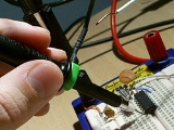
Simple test leads
VoltmeterVoltmeter
A voltmeter is an instrument used for measuring electrical potential difference between two points in an electric circuit. Analog voltmeters move a pointer across a scale in proportion to the voltage of the circuit; digital voltmeters give a numerical display of voltage by use of an analog to...
probes usually consist of single wires that are equipped on one end with a connector that fits the user's voltmeter and on the other end with a rigid plastic section (the probe itself) that allows the user to safely hold the probe while being protected from the danger of electric shock
Electric shock
Electric Shock of a body with any source of electricity that causes a sufficient current through the skin, muscles or hair. Typically, the expression is used to denote an unwanted exposure to electricity, hence the effects are considered undesirable....
. Within the plastic body of the probe, the wire is connected to a rigid, pointed metal tip that makes the actual contact with the DUT.
For most measurements, such as voltage, current, measurement of two-terminal components such as resistors and capacitors, etc. two probes are used, one of which may be positive relative to the other. Voltmeter probes are usually colored red (for the positive probe) and black (for the negative probe). Either probe may be replaced with a wire ending in an alligator clip, allowing a connection to the DUT that does not need to be held. Some probes allow an alligator clip to be screwed onto their ends, covering the metal point.
Ordinary voltmeter probes can be used for voltages up to about 1,000 volt
Volt
The volt is the SI derived unit for electric potential, electric potential difference, and electromotive force. The volt is named in honor of the Italian physicist Alessandro Volta , who invented the voltaic pile, possibly the first chemical battery.- Definition :A single volt is defined as the...
s and currents
Electric current
Electric current is a flow of electric charge through a medium.This charge is typically carried by moving electrons in a conductor such as wire...
of a few amperes. Depending upon the accuracy required, they can be used for frequencies ranging from DC to a few kilohertz
Hertz
The hertz is the SI unit of frequency defined as the number of cycles per second of a periodic phenomenon. One of its most common uses is the description of the sine wave, particularly those used in radio and audio applications....
.
The test leads are usually made with finely stranded wire to keep them flexible. The insulation is chosen to be both flexible and have a breakdown voltage safe at the voltmeter's highest ranges (e.g., 600 volts). The many fine strands and the thick insulation make for wire thicker than ordinary hookup wire, sometimes termed test prod wire.
When very small voltages or currents, very low or very high resistances, etc., are measured, shields, guards, and techniques such as Kelvin sensing are used.
Multiplier probes for voltmeters contain a high resistance network for high voltage measurements,for example, the high voltage in a televisionCRT
Cathode ray tube
The cathode ray tube is a vacuum tube containing an electron gun and a fluorescent screen used to view images. It has a means to accelerate and deflect the electron beam onto the fluorescent screen to create the images. The image may represent electrical waveforms , pictures , radar targets and...
power supply, or for a microwave oven magentron power supply. Readings on the voltmeter must be multiplied by 10 or 100, depending on the probe.
Tweezer probes
Tweezer probes are a pair of simple probes fixed to a tweezerTweezers
Tweezers are tools used for picking up and manipulating objects too small to be easily handled with the human hands. They are probably derived from tongs, pincers, or scissors-like pliers used to grab or hold hot objects since the dawn of recorded history...
mechanism to measure voltages or other electronic circuit parameters between closely spaced pins, operated with one hand.
Pogo pins
Spring probes (a.k.a. "pogo pinPogo pin
A Pogo pin is a device used in electronics to establish a connection between two printed circuit boards. Named by analogy with the pogo stick toy, the pogo pin usually takes the form of a slender cylinder containing two sharp, spring-loaded pins...
s") are spring-loaded pins used in electrical test fixture
Test fixture
A test fixture is something used to consistently test some item, device, or piece of software.-Electronics:Circuit boards, electronic components, and chips are held in place and subjected to controlled electronic test signals. One example is a bed of nails tester.-Software:Test fixture refers to...
s to contact test points, component leads, and other conductive features of the DUT (Device Under Test). These probes are usually press-fit into probe sockets, to allow their easy replacement on test fixture
Test fixture
A test fixture is something used to consistently test some item, device, or piece of software.-Electronics:Circuit boards, electronic components, and chips are held in place and subjected to controlled electronic test signals. One example is a bed of nails tester.-Software:Test fixture refers to...
s which may remain in service for decades, testing many thousands of DUTs in automatic test equipment
Automatic test equipment
Automatic or Automated Test Equipment is any apparatus that performs tests on a device, known as the Device Under Test , using automation to quickly perform measurements and evaluate the test results...
.
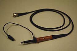
Oscilloscope probes
Oscilloscopes display the instantaneous waveform of varying electrical quantities, unlike other instruments which give numerical values of relatively stable quantities.Oscilloscopes, and other instruments which must acquire an accurate representation of a high-frequency signal use shielded cables. Open wire test leads (flying leads) are likely to pick up interference, so they are not suitable for low-level signals. Furthermore, the inductance of the leads is not negligible at high frequencies, making them unsuitable for this use. Using a shielded cable (i.e., coaxial cable) is better for low-level signals. Coaxial cable has lower inductance, but higher capacitance: a typical 50 ohm cable has about 90 pF per meter. Consequently, a one-meter direct (1×) coaxial probe will load a circuit with a capacitance of about 110 pF and a resistance of 1 megohm.
Passive probes
To minimize loading, attenuator probes (e.g., 10× probes) are used. A typical probe uses a 9 megohm series resistor shunted by a low-value capacitor to make an RC compensated divider with the cable capacitance and scope input. The RC time constants are adjusted to match. For example, the 9 megohm series resistor is shunted by a 12.2 pF capacitor for a time constant of 110 microseconds. The cable capacitance of 90 pF in parallel with the scope input of 20 pF and 1 megohm (total capacitance 110 pF) also gives a time constant of 110 microseconds. In practice, there will be an adjustment so the operator can precisely match the low frequency time constant (called compensating the probe). Matching the time constants makes the attenuation independent of frequency. At low frequencies (where the resistance of R is much less than the reactance of C), the circuit looks like a resistive divider; at high frequencies (resistance much greater than reactance), the circuit looks like a capacitive divider.The result is a frequency compensated probe for modest frequencies that presents a load of about 10 megohms shunted by 12 pF. Although such a probe is an improvement, it does not work when the time scale shrinks to several cable transit times (transit time is typically 5 ns). In that time frame, the cable looks like its characteristic impedance, and there will be reflections from the transmission line mismatch at the scope input and the probe that causes ringing. The modern scope probe uses lossy low capacitance transmission lines and sophisticated frequency shaping networks to make the 10× probe perform well at several hundred megahertz. Consequently, there are other adjustments for completing the compensation.
A directly connected test probe (so called 1× probe) puts the unwanted lead capacitance across the circuit under test. For a typical coaxial cable
Coaxial cable
Coaxial cable, or coax, has an inner conductor surrounded by a flexible, tubular insulating layer, surrounded by a tubular conducting shield. The term coaxial comes from the inner conductor and the outer shield sharing the same geometric axis...
, loading is of the order of 100pF per meter (the length of a typical test lead).
Attenuator probes minimize capacitive loading with an attenuator, but reduce the magnitude of the signal delivered to the instrument. A 10× attenuator will reduce the capacitive load by a factor of about 10. The attenuator must have an accurate ratio over the whole range of frequencies of interest; the input impedance of the instrument becomes part of the attenuator. A DC attenuator with resistive divider is supplemented with capacitors, so that the frequency response is predictable over the range of interest.
The RC time constant matching method works as long as the transit time of the shielded cable is much less than the time scale of interest. That means that the shielded cable can be viewed as a lumped capacitor rather than an inductor. Transit time on a 1 meter cable is about 5 ns. Consequently, these probes will work to a few megahertz, but after that transmission line effects cause trouble.
At high frequencies, the probe impedance will be low.
Capacitance
In electromagnetism and electronics, capacitance is the ability of a capacitor to store energy in an electric field. Capacitance is also a measure of the amount of electric potential energy stored for a given electric potential. A common form of energy storage device is a parallel-plate capacitor...
and ringing
Ringing (signal)
In electronics, signal processing, and video, ringing is unwanted oscillation of a signal, particularly in the step response...
. The resistor serves to minimize the loading that the cable capacitance would impose on the DUT. In series with the normal 1 megohm input impedance of the oscilloscope, the 9 megohm resistor creates a 10× voltage divider so such probes are normally known as either low cap(acitance) probes or 10× probes, often printed with the letter X or x instead of the multiplication sign, and usually spoken of as "a times-ten probe".
Because the oscilloscope input has some parasitic capacitance in parallel with the 1 megohm resistance, the 9 megohm resistor must also be bypassed by a capacitor to prevent it from forming a severe RC low-pass filter
Low-pass filter
A low-pass filter is an electronic filter that passes low-frequency signals but attenuates signals with frequencies higher than the cutoff frequency. The actual amount of attenuation for each frequency varies from filter to filter. It is sometimes called a high-cut filter, or treble cut filter...
with the 'scope's parasitic capacitance. The amount of bypass capacitance must be carefully matched with the input capacitance of the oscilloscope so that the capacitors also form a 10× voltage divider. In this way, the probe provides a uniform 10× attenuation from DC (with the attenuation provided by the resistors) to very high AC frequencies (with the attenuation provided by the capacitors).
In the past, the bypass capacitor in the probe head was adjustable (to achieve this 10× attenuation). More modern probe designs use a laser-trimmed
Laser trimming
Laser trimming is the manufacturing process of using a laser to adjust the operating parameters of an electronic circuit.One of the most common applications uses a laser to burn away small portions of resistors, raising their resistance value...
thick-film
Thick film technology
Thick film technology is used to produce electronic devices such as surface mount devices, hybrid integrated circuits and sensors.Thick film circuits are widely used, in automotive industry, both in sensors ex...
electronic circuit in the head that combines the 9 megohm resistor with a fixed-value bypass capacitor; they then place a small adjustable capacitor in parallel with the oscilloscope's input capacitance. Either way, the probe must be adjusted so that it provides uniform attenuation at all frequencies. This is referred to as compensating the probe. Compensation is usually accomplished by probing a square wave
Square wave
A square wave is a kind of non-sinusoidal waveform, most typically encountered in electronics and signal processing. An ideal square wave alternates regularly and instantaneously between two levels...
and adjusting the compensating capacitor until the oscilloscope displays the most accurate waveshape. Newer, faster probes have more complex compensation arrangements and may occasionally require further adjustments.
100× passive probes are also available, as are some designs specialized for use at very high voltages (up to 25 kV).
Passive probes usually connect to the oscilloscope using a BNC connector
BNC connector
The BNC connector ' is a common type of RF connector used for coaxial cable. It is used with radio, television, and other radio-frequency electronic equipment, test instruments, video signals, and was once a popular computer network connector. BNC connectors are made to match the characteristic...
. Most 10× probes are equivalent to a load of about 10-15 pF and 10 megohms on the DUT, with 100× probes loading the circuit less.
Lo Z probes
Z0 probes are a specialized type of low-capacitance passive probe used in low-impedanceElectrical impedance
Electrical impedance, or simply impedance, is the measure of the opposition that an electrical circuit presents to the passage of a current when a voltage is applied. In quantitative terms, it is the complex ratio of the voltage to the current in an alternating current circuit...
, very-high-frequency circuits. They are similar in design to 10× passive probes but at much lower impedance levels. The probe cables usually have a characteristic impedance of 50 ohms and connect to oscilloscopes with a matched 50 ohm (rather than 1 megohm) input impedance. At the tip, these probes use a 450 ohm (for 10× attenuation) or 950 ohm (for 20× attenuation) series resistor (rather than the 9 megohm resistor of the 10× probe). High-impedance scope probes are designed for the conventional 1 megohm oscilloscope, but at high frequencies mismatch between the scope input impedance and the cable impedance presents a transmission line mismatch. A high frequency oscilloscope presents a matched load (usually 50 ohms) at its input, which minimizes reflections at the scope.
In principle this type of probe can be used at any frequency, but at DC and lower frequencies the low 50 ohm impedance will load the circuit under test unacceptably—parasitic impedances limit very-high-frequency circuits to operating at low impedance, but at lower frequencies high impedances are normal. An attenuator can be used to minimize loading. These probes are also called resistive divider probes, since a 50 ohm transmission line presents a purely resistive load. A 21× divider probe consists of a 1000 ohm series resistor and a short 50 ohm transmission line . Tektronix sells a 10× divider probe with 9 GHz bandwidth with a 450 ohm series resistor.
The Z0 name refers to the fact that the coaxial cable matches the characteristic impedance
Characteristic impedance
The characteristic impedance or surge impedance of a uniform transmission line, usually written Z_0, is the ratio of the amplitudes of a single pair of voltage and current waves propagating along the line in the absence of reflections. The SI unit of characteristic impedance is the ohm...
of the oscilloscope. This provides far better high-frequency performance than an unmatched passive probe can achieve, but at the expense of the low 500-ohm load offered by the probe tip to the DUT. Parasitic capacitance at the probe tip is very low so, for very high-frequency signals, the Z0 probe can offer lower loading than any hi-Z probe and even many active probes.
Active scope probes
Active scope probes use a small, usually FET-based amplifierAmplifier
Generally, an amplifier or simply amp, is a device for increasing the power of a signal.In popular use, the term usually describes an electronic amplifier, in which the input "signal" is usually a voltage or a current. In audio applications, amplifiers drive the loudspeakers used in PA systems to...
mounted directly within the probe head, and a screened lead. By doing this they are able to obtain exceptionally low parasitic capacitance and high DC resistance (It is common to see capacitance of 1 picofarad or less with 1 megohm resistance). They are connected to the oscilloscope in the same fashion as passive Z0 probes (using 50 ohm coaxial cable terminated at the oscilloscope's input).
Active probes have several disadvantages which have kept them from replacing passive probes for all applications:
- They are several times more expensive than passive probes.
- They require power (but this is usually supplied by the oscilloscope).
- Their dynamic range is limited, sometimes as low as 3 to 5 volts.
- They can be damaged by overvoltage, either from the signal or electrostatic dischargeElectrostatic dischargeElectrostatic discharge is a serious issue in solid state electronics, such as integrated circuits. Integrated circuits are made from semiconductor materials such as silicon and insulating materials such as silicon dioxide...
.
To overcome their often-limited dynamic range, many active probes allow the user to introduce an offset voltage. The total dynamic range is still limited, but the user may be able to adjust its centerpoint so that voltages in the range of, for example, zero to five volts may be measured rather than -2.5 to +2.5.
Because of their inherent low voltage rating, there is little need to provide a large amount of insulation to ensure operator safety against electric shock. This allows the probe heads on active probes to be extremely small, making them very convenient for use with modern high-density electronic packaging. Because of their size and excellent electrical characteristics, they are strongly preferred for troubleshooting digital electronics.
Before the advent of high-performance solid-state electronics a very few active probes were built using small vacuum tubes as the amplifiers.
At extreme high frequencies a modern digital scope requires that the user solder a preamp to the DUT to get 50GS/s, 20 GHz performance.
Differential probes
Differential probes are optimized for acquiring differential signalsDifferential signaling
Differential signaling is a method of transmitting information electrically by means of two complementary signals sent on two separate wires. The technique can be used for both analog signaling, as in some audio systems, and digital signaling, as in RS-422, RS-485, Ethernet , PCI Express and USB...
. To maximize the common-mode rejection ratio
Common-mode rejection ratio
The common-mode rejection ratio of a differential amplifier is the tendency of the devices to reject the input signals common to both input leads...
(CMRR), differential probes must provide two signal paths that are as nearly identical as possible, matched in overall attenuation, frequency response, and time delay.
In the past, this was done by designing passive probes with two signal paths, requiring a differential amplifier
Differential amplifier
A differential amplifier is a type of electronic amplifier that amplifies the difference between two voltages but does not amplify the particular voltages.- Theory :Many electronic devices use differential amplifiers internally....
stage at or near the oscilloscope. (A very few early probes fitted the differential amplifier into a rather-bulky probe head using vacuum tubes.) With advances in solid-state electronics, it has become practical to put the differential amplifier directly within the probe head, greatly easing the requirements on the rest of the signal path (since it now becomes single-ended rather than differential and the need to match parameters on the signal path is removed). A modern differential probe usually has two metal extensions which can be adjusted by the operator to simultaneously touch the appropriate two points on the DUT. Very high CMRRs are thereby made possible.
Additional probe features
All scope probes contain some facility for grounding (earthing) the probe to the circuit's reference voltage. This is usually accomplished by connecting a very short pigtail wire from the probe head to ground. Inductance in the ground wire can lead to distortion in the observed signal, so this wire is kept as short as possible. Some probes use a small ground foot instead of any wire, allowing the ground link to be as short as 10 mm.Most probes allow a variety of "tips" to be installed. A small, pointed tip is the most common, but "hook tips" that hold onto the test point are also very commonly used. Tips that have a small plastic insulating foot with indentations into it can make it easier to probe very-fine-pitch integrated circuits; the indentations mate with the pitch of the IC leads, stabilizing the probe against the shaking of the user's hand and thereby help to maintain contact on the desired pin. Various styles of feet accommodate various pitches of the IC leads. Different types of tips can also be used for probes for other instruments.
Some probes contain a push button. Pressing the button will either disconnect the signal (and send a ground signal to the 'scope) or cause the 'scope to identify the trace in some other way. This feature is very useful when simultaneously using more than one probe as it lets the user correlate probes and traces on the 'scope screen.
Some probe designs have additional pins surrounding the BNC or use a more complex connector than a BNC. These extra connections allow the probe to inform the oscilloscope of its attenuation factor (10×, 100×, other). The oscilloscope can then adjust its user displays to automatically take into account the attenuation and other factors caused by the probe. These extra pins can also be used to supply power to active probes.
Some ×10 probes have a "×1/×10" switch. The "×1" position bypasses the attenuator and compensating network, and can be used when working with very small signals that would be below the scope's sensitivity limit if attenuated by ×10.
Interchangeability
Because of their standardized design, passive probes (including Z0 probes) from any manufacturer can usually be used with any oscilloscope (although specialized features such as the automatic readout adjustment may not work). Passive probes with voltage dividers may not be compatible with a particular scope. The compensation adjustment capacitor only allows for compensation over a small range of oscilloscope input capacitance values. The probe compensation range must be compatible with the oscilloscope input capacitance.On the other hand, active probes are almost always vendor-specific due to their power requirements, offset voltage controls, etc. Probe manufacturers sometimes offer external amplifiers or plug-in AC power adapters that allow their probes to be used with any oscilloscope.
High-voltage probes
By inserting a large resistorResistor
A linear resistor is a linear, passive two-terminal electrical component that implements electrical resistance as a circuit element.The current through a resistor is in direct proportion to the voltage across the resistor's terminals. Thus, the ratio of the voltage applied across a resistor's...
in series with the probe and providing good electrical insulation
Electrical insulation
thumb|250px|[[Coaxial Cable]] with dielectric insulator supporting a central coreThis article refers to electrical insulation. For insulation of heat, see Thermal insulation...
, it is possible to create a probe that allows an ordinary voltmeter to measure very high voltages (up to about 50 kV). The value of the resistor must be chosen to form an appropriate voltage divider with the input resistance of the voltmeter. Because of the very high value of the resistor needed (several megohms
Ohm
The ohm is the SI unit of electrical resistance, named after German physicist Georg Simon Ohm.- Definition :The ohm is defined as a resistance between two points of a conductor when a constant potential difference of 1 volt, applied to these points, produces in the conductor a current of 1 ampere,...
), high voltage probes are mainly used for measuring DC and low frequency AC; the RC circuit
RC circuit
A resistor–capacitor circuit ', or RC filter or RC network, is an electric circuit composed of resistors and capacitors driven by a voltage or current source...
that is formed with the parasitic capacitance
Parasitic capacitance
In electrical circuits, parasitic capacitance, stray capacitance or, when relevant, self-capacitance , is an unavoidable and usually unwanted capacitance that exists between the parts of an electronic component or circuit simply because of their proximity to each other...
of the voltmeter input will attenuate higher frequencies.
Current probes
A current probe generates a voltage proportional to a current in the circuit being measured; as the proportionality constant is known, instruments that respond to voltage can be calibrated to indicate current. Current probes can be used both by measuring instruments and oscilloscopes.Sampling resistor
The classic current probe is a low valued resistor (a "sampling resistor" or "current shunt") inserted in the current's path. The current is determined by measuring the voltage drop across the resistor and using Ohm's lawOhm's law
Ohm's law states that the current through a conductor between two points is directly proportional to the potential difference across the two points...
. The sampling resistance needs to be small enough not to affect circuit operation significantly, but large enough to provide a good reading. The method is valid for both AC and DC measurements. A disadvantage of this method is the need to break the circuit to introduce the shunt. Another problem is measuring the voltage across the shunt when common-mode voltages are present; a differential voltage measurement is needed.
Alternating current probes
Alternating currents are relatively easy to measure as transformers can be used.A current transformer
Current transformer
In electrical engineering, a current transformer is used for measurement of electric currents. Current transformers, together with voltage transformers , are known as instrument transformers...
is commonly used to measure alternating currents. The current to be measured is forced through the primary winding (often a single turn) and the current through the secondary winding is found by measuring the voltage across a current-sense resistor (or "burden resistor"). The secondary winding has a burden resistor to set the current scale. The properties of a transformer offer many advantages. The current transformer rejects common mode voltages, so an accurate single-ended voltage measurement can be made on a grounded secondary. The effective series resistance
 of the primary winding is set by the burden resistor on the secondary winding
  and the transformer turns ratio
  , where:
  .
. The core of some current transformers is split and hinged; it is opened and clipped around the wire to be sensed, then closed, making it unnecessary to free one end of the conductor and thread it through the core.
Another clip-on design is the Rogowski coil
Rogowski coil
A Rogowski coil, named after Walter Rogowski, is an electrical device for measuring alternating current or high speed current pulses. It consists of a helical coil of wire with the lead from one end returning through the centre of the coil to the other end, so that both terminals are at the same...
. It is a magnetically balanced coil that measures current by electronically evaluating the line integral around a current.
High-frequency, small-signal, passive current probes typically have a frequency range of several kilohertz to over 100 MHz. The Tektronix P6022 has a range from 935 Hz to 200 MHz.
Direct-current probes
Transformers cannot be used to probe direct currentDirect current
Direct current is the unidirectional flow of electric charge. Direct current is produced by such sources as batteries, thermocouples, solar cells, and commutator-type electric machines of the dynamo type. Direct current may flow in a conductor such as a wire, but can also flow through...
s (DC).
Some DC probe designs use the nonlinear properties of a magnetic material to measure DC.
Other current probes use Hall effect
Hall effect
The Hall effect is the production of a voltage difference across an electrical conductor, transverse to an electric current in the conductor and a magnetic field perpendicular to the current...
sensors to measure the magnetic field
Magnetic field
A magnetic field is a mathematical description of the magnetic influence of electric currents and magnetic materials. The magnetic field at any given point is specified by both a direction and a magnitude ; as such it is a vector field.Technically, a magnetic field is a pseudo vector;...
around a wire produced by an electric current
Electric current
Electric current is a flow of electric charge through a medium.This charge is typically carried by moving electrons in a conductor such as wire...
through the wire without the need to interrupt the circuit to fit the probe. They are available for both voltmeters and oscilloscopes. Most current probes are self-contained, drawing power from a battery or the instrument, but a few require the use of an external amplifier unit. (See also: Clamp meter)
Hybrid AC/DC current probes
More advanced current probes combine a Hall effect sensor with a current transformer. The Hall effect sensor measures the DC and low frequency components of the signal and the current transformer measures the high frequency components. These signals are combined in the amplifier circuit to yield a wide band signal extending from DC to over 50 MHz. The Tektronix A6302 current probe and AM503 amplifier combination is an example of such a system.Near-field probes
Near-field probes allow the measurement of an electromagnetic fieldElectromagnetic field
An electromagnetic field is a physical field produced by moving electrically charged objects. It affects the behavior of charged objects in the vicinity of the field. The electromagnetic field extends indefinitely throughout space and describes the electromagnetic interaction...
. They are commonly used to measure electrical noise
Noise
In common use, the word noise means any unwanted sound. In both analog and digital electronics, noise is random unwanted perturbation to a wanted signal; it is called noise as a generalisation of the acoustic noise heard when listening to a weak radio transmission with significant electrical noise...
and other undesirable electromagnetic radiation
Electromagnetic radiation
Electromagnetic radiation is a form of energy that exhibits wave-like behavior as it travels through space...
from the DUT, although they can also be used to spy on the workings of the DUT without introducing much loading
Loading
In electrical transmission lines, the term loading means the insertion of impedance into a circuit to change the characteristics of the circuit....
into the circuitry.
They are commonly connected to spectrum analyzer
Spectrum analyzer
A spectrum analyzer measures the magnitude of an input signal versus frequency within the full frequency range of the instrument. The primary use is to measure the power of the spectrum of known and unknown signals...
s.
Temperature probes
Voltmeters commonly allow the connection of a temperature probe, allowing them to make contact measurements of surface temperatures. The probe may be a thermistorThermistor
A thermistor is a type of resistor whose resistance varies significantly with temperature, more so than in standard resistors. The word is a portmanteau of thermal and resistor...
, a thermocouple
Thermocouple
A thermocouple is a device consisting of two different conductors that produce a voltage proportional to a temperature difference between either end of the pair of conductors. Thermocouples are a widely used type of temperature sensor for measurement and control and can also be used to convert a...
, or a temperature-dependent resistor
Resistance thermometer
Resistance thermometers, also called resistance temperature detectors or resistive thermal devices , are sensors used to measure temperature by correlating the resistance of the RTD element with temperature. Most RTD elements consist of a length of fine coiled wire wrapped around a ceramic or glass...
, usually made of platinum
Platinum
Platinum is a chemical element with the chemical symbol Pt and an atomic number of 78. Its name is derived from the Spanish term platina del Pinto, which is literally translated into "little silver of the Pinto River." It is a dense, malleable, ductile, precious, gray-white transition metal...
; the probe and the instrument using it must be designed to work together.
Demodulator probes
To measure or display the modulating waveform of a modulatedModulation
In electronics and telecommunications, modulation is the process of varying one or more properties of a high-frequency periodic waveform, called the carrier signal, with a modulating signal which typically contains information to be transmitted...
high-frequency signal—for example, an amplitude-modulated
Amplitude modulation
Amplitude modulation is a technique used in electronic communication, most commonly for transmitting information via a radio carrier wave. AM works by varying the strength of the transmitted signal in relation to the information being sent...
radio signal—a probe fitted with a simple diode
Diode
In electronics, a diode is a type of two-terminal electronic component with a nonlinear current–voltage characteristic. A semiconductor diode, the most common type today, is a crystalline piece of semiconductor material connected to two electrical terminals...
demodulator can be used. The probe will output the modulating waveform without the high-frequency carrier
Carrier wave
In telecommunications, a carrier wave or carrier is a waveform that is modulated with an input signal for the purpose of conveying information. This carrier wave is usually a much higher frequency than the input signal...
.