

Operational amplifier applications
Encyclopedia
This article illustrates some typical applications of operational amplifier
s. A simplified schematic notation is used, and the reader is reminded that many details such as device selection and power supply connections are not shown.
Resistors used in practical solid-state op-amp circuits are typically in the kΩ range. Resistors much greater than 1 MΩ cause excessive thermal noise and make the circuit operation susceptible to significant errors due to bias or leakage currents.
Practical operational amplifiers draw a small current from each of their inputs due to bias requirements and leakage. These currents flow through the resistances connected to the inputs and produce small voltage drops across those resistances. In AC signal applications this seldom matters. If high-precision DC operation is required, however, these voltage drops need to be considered. The design technique is to try to ensure that these voltage drops are equal for both inputs, and therefore cancel. If these voltage drops are equal and the common-mode rejection ratio
of the operational amplifier is good, there will be considerable cancellation and improvement in DC accuracy.
If the input currents into the operational amplifier are equal, to reduce offset voltage the designer must ensure that the DC resistance looking out of each input is also matched. In general input currents differ, the difference being called the input offset current, Ios. Matched external input resistances Rin will still produce an input voltage error of Rin·Ios . Most manufacturers provide a method for tuning the operational amplifier to balance the input currents (e.g., "offset null" or "balance" pins that can interact with an external voltage source attached to a potentiometer). Otherwise, a tunable external voltage can be added to one of the inputs in order to balance out the offset effect. In cases where a design calls for one input to be short-circuited to ground, that short circuit can be replaced with a variable resistance that can be tuned to mitigate the offset problem.
Note that many operational amplifiers that have MOSFET
-based input stages have input leakage currents that will truly be negligible to most designs.
Power supply imperfections (e.g., power signal ripple, non-zero source impedance) may lead to noticeable deviations from ideal operational amplifier behavior. For example, operational amplifiers have a specified power supply rejection ratio
that indicates how well the output can reject signals that appear on the power supply inputs. Power supply inputs are often noisy in large designs because the power supply is used by nearly every component in the design, and inductance effects prevent current from being instantaneously delivered to every component at once. As a consequence, when a component requires large injections of current (e.g., a digital component that is frequently switching from one state to another), nearby components can experience sagging at their connection to the power supply. This problem can be mitigated with copious use of bypass capacitor
s connected across each power supply pin and ground. When bursts of current are required by a component, the component can bypass the power supply by receiving the current directly from the nearby capacitor (which is then slowly recharged by the power supply).
Additionally, current drawn into the operational amplifier from the power supply can be used as inputs to external circuitry that augment the capabilities of the operational amplifier. For example, an operational amplifier may not be fit for a particular high-gain application because its output would be required to generate signals outside of the safe range generated by the amplifier. In this case, an external push–pull amplifier can be controlled by the current into and out of the operational amplifier. Thus, the operational amplifier may itself operate within its factory specified bounds while still allowing the negative feedback path to include a large output signal well outside of those bounds.

An inverting amplifier uses negative feedback
to invert (i.e., negate
) and amplify
a voltage. In particular, the Rin–Rf resistor network acts as an electronic seesaw
(i.e., a class-1 lever
) where the inverting (i.e., −) input of the operational amplifier is like a fulcrum
about which the seesaw pivots. That is, because the operational amplifier is in a negative-feedback configuration, its internal high gain effectively fixes the inverting (i.e., −) input at the same 0 V (ground) voltage of the non-inverting (i.e., +) input, which is similar to the stiff mechanical support provided by the fulcrum of the seesaw. Continuing the analogy,
Hence, the amplifier output is related to the input as in .
.
So the voltage gain of the amplifier is where the negative sign is a convention indicating that the output is negated. For example, if Rf is 10 kΩ and Rin is 1 kΩ, then the gain is −10 kΩ/1 kΩ, or −10 (or −10 V/V). Moreover, the input impedance
of the device is because the operational amplifier's inverting (i.e., −) input is a virtual ground
.
In a real operational amplifier, the current into its two inputs is small but non-zero (e.g., due to input bias currents). The current into the inverting (i.e., −) input of the operational amplifier is drawn across the Rin and Rf resistors in parallel, which appears like a small parasitic voltage difference between the inverting (i.e., −) and non-inverting (i.e., +) inputs of the operational amplifier. To mitigate this practical problem, a third resistor of value can be added between the non-inverting (i.e., +) input and the true ground. This resistor does not affect the idealized operation of the device because no current enters the ideal non-inverting input. However, in the practical case, if input currents are roughly equivalent, the voltage added at the inverting input will match the voltage at the non-inverting input, and so this common-mode signal
will be ignored by the operational amplifier (which operates on differences
between its inputs).

Amplifies a voltage (multiplies by a constant greater than 1)
The circuit shown computes the difference
of two voltages multiplied by some constant. In particular, the output voltage is:

The differential input impedance Zin (i.e., the impedance between the two input pins) is approximately R1 + R2. The input currents vary with the operating point of the circuit. Consequently, if the two sources feeding this circuit have appreciable output impedance
, then non-linearities can appear in the output. An instrumentation amplifier mitigates these problems.

Used as a buffer amplifier
to eliminate loading effects (e.g., connecting a device with a high source impedance to a device with a low input impedance
).

 (realistically, the differential input impedance of the op-amp itself, 1 MΩ to 1 TΩ)
Due to the strong (i.e., unity gain) feedback and certain non-ideal characteristics of real operational amplifiers, this feedback system is prone to have poor stability margin
s. Consequently, the system may be unstable
when connected to sufficiently capacitive loads. In these cases, a lag compensation
network (e.g., connecting the load to the voltage follower through a resistor) can be used to restore stability. The manufacturer data sheet for the operational amplifier may provide guidance for the selection of components in external compensation networks. Alternatively, another operational amplifier can be chosen that has more appropriate internal compensation.
 A summing amplifier sums several (weighted) voltages:


Combines very high input impedance
, high common-mode rejection, low DC offset, and other properties used in making very accurate, low-noise measurements
Produces a very low distortion sine wave
. Uses negative temperature compensation in the form of a light bulb or diode.
By using an RC network to add slow negative feedback
to the inverting Schmitt trigger, a relaxation oscillator
is formed. The feedback through the RC network causes the Schmitt trigger output to oscillate in an endless symmetric square wave
(i.e., the Schmitt trigger in this configuration is an astable multivibrator).
Bistable
output that indicates which of the two inputs has a higher voltage. That is,
where and
and  are nominally the positive and negative supply voltages (which are not shown in the diagram).
The threshold detector with hysteresis
, very similar to the zero crossing threshold detector
, consists of an operational amplifier
and a series of resistors that provide hysteresis. Like other detectors, this device functions as a voltage
switch, but with an important difference. The state of the detector output is not directly affected by input voltage, but instead by the voltage drop across its input terminals (here, referred to as Va). From Kirchhoff's Current Law
, this value depends both on Vin and the output voltage of the threshold detector itself, both multiplied by a resistor ratio.
Unlike the zero crossing detector, the detector with hysteresis does not switch when Vin is zero, rather the output becomes Vsat+ when Va becomes positive and Vsat- when Va becomes negative. Further examination of the Va equation reveals that Vin can exceed zero (positive or negative) by a certain magnitude before the output of the detector is caused to switch. By adjusting the value of R1, the magnitude of Vin that will cause the detector to switch can be increased or decreased. This property often proves very useful in various applications, including signal generators.
with hysteresis
.

In this configuration, the input voltage is applied through the resistor (which may be the source internal resistance) to the non-inverting input and the inverting input is grounded or referenced. The hysteresis curve is non-inverting and the switching thresholds are
  where
where  is the greatest output magnitude of the operational amplifier.

Alternatively, the input source and the ground may be swapped. Now the input voltage is applied directly to the inverting input and the non-inverting input is grounded or referenced. The hysteresis curve is inverting and the switching thresholds are . Such a configuration is used in the relaxation oscillator shown below.
 Integrates
the (inverted) signal over time
(where and
and  are functions of time,
  is the output voltage of the integrator at time t = 0.)
Differentiates
the (inverted) signal over time.

Simulates an inductor
(i.e., provides inductance
without the use of a possibly costly inductor). The circuit exploits the fact that the current flowing through a capacitor behaves through time as the voltage across an inductor. The capacitor used in this circuit is smaller than the inductor it simulates and its capacitance is less subject to changes in value due to environmental changes.
This circuit is unsuitable for applications relying on the back EMF property of an inductor as this will be limited in a gyrator circuit to the voltage supplies of the op-amp.
Creates a resistor
having a negative value for any signal generator

In general, the components ,
,  , and
, and  need not be resistors; they can be any component that can be described with an impedance
.
The voltage drop VF across the forward biased diode in the circuit of a passive rectifier is undesired. In this active version, the problem is solved by connecting the diode in the negative feedback loop. The op-amp compares the output voltage across the load with the input voltage and increases its own output voltage with the value of VF. As a result, the voltage drop VF is compensated and the circuit behaves very nearly as an ideal (super) diode
with VF = 0 V.
The circuit has speed limitations at high frequency because of the slow negative feedback and due to the low slew rate of many non-ideal op-amps.
Note that this implementation does not consider temperature stability and other non-ideal effects.
where is the saturation current
and is the thermal voltage.
when the voltage is greater than zero, it can be approximated by:

The output voltage is given by:
Application note – Texas Instruments
Application note
Operational amplifier
An operational amplifier is a DC-coupled high-gain electronic voltage amplifier with a differential input and, usually, a single-ended output...
s. A simplified schematic notation is used, and the reader is reminded that many details such as device selection and power supply connections are not shown.
Input offset problems
It is important to note that the equations shown below, pertaining to each type of circuit, assume that an ideal op amp is used. Those interested in construction of any of these circuits for practical use should consult a more detailed reference. See the External links and Further reading sections.Resistors used in practical solid-state op-amp circuits are typically in the kΩ range. Resistors much greater than 1 MΩ cause excessive thermal noise and make the circuit operation susceptible to significant errors due to bias or leakage currents.
Practical operational amplifiers draw a small current from each of their inputs due to bias requirements and leakage. These currents flow through the resistances connected to the inputs and produce small voltage drops across those resistances. In AC signal applications this seldom matters. If high-precision DC operation is required, however, these voltage drops need to be considered. The design technique is to try to ensure that these voltage drops are equal for both inputs, and therefore cancel. If these voltage drops are equal and the common-mode rejection ratio
Common-mode rejection ratio
The common-mode rejection ratio of a differential amplifier is the tendency of the devices to reject the input signals common to both input leads...
of the operational amplifier is good, there will be considerable cancellation and improvement in DC accuracy.
If the input currents into the operational amplifier are equal, to reduce offset voltage the designer must ensure that the DC resistance looking out of each input is also matched. In general input currents differ, the difference being called the input offset current, Ios. Matched external input resistances Rin will still produce an input voltage error of Rin·Ios . Most manufacturers provide a method for tuning the operational amplifier to balance the input currents (e.g., "offset null" or "balance" pins that can interact with an external voltage source attached to a potentiometer). Otherwise, a tunable external voltage can be added to one of the inputs in order to balance out the offset effect. In cases where a design calls for one input to be short-circuited to ground, that short circuit can be replaced with a variable resistance that can be tuned to mitigate the offset problem.
Note that many operational amplifiers that have MOSFET
MOSFET
The metal–oxide–semiconductor field-effect transistor is a transistor used for amplifying or switching electronic signals. The basic principle of this kind of transistor was first patented by Julius Edgar Lilienfeld in 1925...
-based input stages have input leakage currents that will truly be negligible to most designs.
Power supply effects
Although the power supplies are not shown in the operational amplifier designs below, they can be critical in operational amplifier design.Power supply imperfections (e.g., power signal ripple, non-zero source impedance) may lead to noticeable deviations from ideal operational amplifier behavior. For example, operational amplifiers have a specified power supply rejection ratio
Power supply rejection ratio
In electronics, power supply rejection ratio or PSRR is a term widely used in the electronic amplifier or voltage regulator datasheets; used to describe the amount of noise from a power supply that a particular device can reject.-Definition:The PSRR is defined as the ratio of the change in supply...
that indicates how well the output can reject signals that appear on the power supply inputs. Power supply inputs are often noisy in large designs because the power supply is used by nearly every component in the design, and inductance effects prevent current from being instantaneously delivered to every component at once. As a consequence, when a component requires large injections of current (e.g., a digital component that is frequently switching from one state to another), nearby components can experience sagging at their connection to the power supply. This problem can be mitigated with copious use of bypass capacitor
Decoupling capacitor
A decoupling capacitor is a capacitor used to decouple one part of an electrical network from another. Noise caused by other circuit elements is shunted through the capacitor, reducing the effect they have on the rest of the circuit....
s connected across each power supply pin and ground. When bursts of current are required by a component, the component can bypass the power supply by receiving the current directly from the nearby capacitor (which is then slowly recharged by the power supply).
Additionally, current drawn into the operational amplifier from the power supply can be used as inputs to external circuitry that augment the capabilities of the operational amplifier. For example, an operational amplifier may not be fit for a particular high-gain application because its output would be required to generate signals outside of the safe range generated by the amplifier. In this case, an external push–pull amplifier can be controlled by the current into and out of the operational amplifier. Thus, the operational amplifier may itself operate within its factory specified bounds while still allowing the negative feedback path to include a large output signal well outside of those bounds.
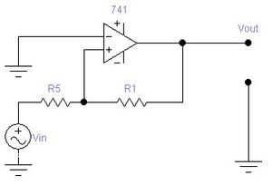
Inverting amplifier
An inverting amplifier uses negative feedback
Negative feedback
Negative feedback occurs when the output of a system acts to oppose changes to the input of the system, with the result that the changes are attenuated. If the overall feedback of the system is negative, then the system will tend to be stable.- Overview :...
to invert (i.e., negate
Negation (algebra)
Negation is the mathematical operation that reverses the sign of a number. Thus the negation of a positive number is negative, and the negation of a negative number is positive. The negation of zero is zero...
) and amplify
Amplifier
Generally, an amplifier or simply amp, is a device for increasing the power of a signal.In popular use, the term usually describes an electronic amplifier, in which the input "signal" is usually a voltage or a current. In audio applications, amplifiers drive the loudspeakers used in PA systems to...
a voltage. In particular, the Rin–Rf resistor network acts as an electronic seesaw
Seesaw
A seesaw is a long, narrow board pivoted in the middle so that, as one end goes up, the other goes down.-Mechanics:Mechanically a seesaw is a lever and fulcrum....
(i.e., a class-1 lever
Lever
In physics, a lever is a rigid object that is used with an appropriate fulcrum or pivot point to either multiply the mechanical force that can be applied to another object or resistance force , or multiply the distance and speed at which the opposite end of the rigid object travels.This leverage...
) where the inverting (i.e., −) input of the operational amplifier is like a fulcrum
Fulcrum
Fulcrum is the support about which a lever pivots. It may also refer to:* Fulcrum , part of a percussionist's grip* MiG-29 Fulcrum, a Soviet fighter aircraftIn fiction:...
about which the seesaw pivots. That is, because the operational amplifier is in a negative-feedback configuration, its internal high gain effectively fixes the inverting (i.e., −) input at the same 0 V (ground) voltage of the non-inverting (i.e., +) input, which is similar to the stiff mechanical support provided by the fulcrum of the seesaw. Continuing the analogy,
- Just as the movement of one end of the seesaw is opposite the movement of the other end of the seesaw, positive movement away from 0 V at the input of the Rin–Rf network is matched by negative movement away from 0 V at the output of the network; thus, the amplifier is said to be inverting.
- In the seesaw analogy, the mechanical momentMoment (physics)In physics, the term moment can refer to many different concepts:*Moment of force is the tendency of a force to twist or rotate an object; see the article torque for details. This is an important, basic concept in engineering and physics. A moment is valued mathematically as the product of the...
or torqueTorqueTorque, moment or moment of force , is the tendency of a force to rotate an object about an axis, fulcrum, or pivot. Just as a force is a push or a pull, a torque can be thought of as a twist....
from the force on one side of the fulcrum is balanced exactly by the force on the other side of the fulcrum; consequently, asymmetric lengths in the seesaw allow for small forces on one side of the seesaw to generate large forces on the other side of the seesaw. In the inverting amplifier, electrical current, like torque, is conserved across the Rin–Rf network and relative differences between the Rin and Rf resistors allow small voltages on one side of the network to generate large voltages (with opposite sign) on the other side of the network. Thus, the device amplifies (and inverts) the input voltage. However, in this analogy, it is the reciprocalMultiplicative inverseIn mathematics, a multiplicative inverse or reciprocal for a number x, denoted by 1/x or x−1, is a number which when multiplied by x yields the multiplicative identity, 1. The multiplicative inverse of a fraction a/b is b/a. For the multiplicative inverse of a real number, divide 1 by the...
s of the resistances (i.e., the conductances or admittanceAdmittanceIn electrical engineering, the admittance is a measure of how easily a circuit or device will allow a current to flow. It is defined as the inverse of the impedance . The SI unit of admittance is the siemens...
s) that play the role of lengths in the seesaw.
Hence, the amplifier output is related to the input as in
.So the voltage gain of the amplifier is
where the negative sign is a convention indicating that the output is negated. For example, if Rf is 10 kΩ and Rin is 1 kΩ, then the gain is −10 kΩ/1 kΩ, or −10 (or −10 V/V). Moreover, the input impedanceInput impedance
The input impedance of an electrical network is the equivalent impedance "seen" by a power source connected to that network. If the source provides known voltage and current, such impedance can be calculated using Ohm's Law...
of the device is
because the operational amplifier's inverting (i.e., −) input is a virtual groundVirtual ground
Virtual ground is a node of the circuit that is maintained at a steady reference potential, without being connected directly to the reference potential...
.
In a real operational amplifier, the current into its two inputs is small but non-zero (e.g., due to input bias currents). The current into the inverting (i.e., −) input of the operational amplifier is drawn across the Rin and Rf resistors in parallel, which appears like a small parasitic voltage difference between the inverting (i.e., −) and non-inverting (i.e., +) inputs of the operational amplifier. To mitigate this practical problem, a third resistor of value
can be added between the non-inverting (i.e., +) input and the true ground. This resistor does not affect the idealized operation of the device because no current enters the ideal non-inverting input. However, in the practical case, if input currents are roughly equivalent, the voltage added at the inverting input will match the voltage at the non-inverting input, and so this common-mode signalCommon-mode signal
Common-mode signal is the component of an analog signal which is present with one sign on all considered conclusions. In electronics where the signal is transferred with differential voltage use, the common-mode signal is called a half-sum of voltages:...
will be ignored by the operational amplifier (which operates on differences
Differential amplifier
A differential amplifier is a type of electronic amplifier that amplifies the difference between two voltages but does not amplify the particular voltages.- Theory :Many electronic devices use differential amplifiers internally....
between its inputs).
Non-inverting amplifier
Amplifies a voltage (multiplies by a constant greater than 1)
- Input impedance
- The input impedance is at least the impedance between non-inverting (
 ) and inverting (
 ) inputs, which is typically 1 MΩ to 10 TΩ, plus the impedance of the path from the inverting (
 ) input to ground (i.e.,
  in parallel with
  ).
). - Because negative feedback ensures that the non-inverting and inverting inputs match, the input impedance is actually much higher.
- The input impedance is at least the impedance between non-inverting (
- Although this circuit has a large input impedance, it suffers from error of input bias current.
- The non-inverting (
 ) and inverting (
 ) inputs draw small leakage currents into the operational amplifier.
 - These input currents generate voltages that act like unmodeled input offsets. These unmodeled effects can lead to noise on the output (e.g., offsets or drift).
- Assuming that the two leaking currents are matched, their effect can be mitigated by ensuring the DC impedance looking out of each input is the same.
- The voltage produced by each bias current is equal to the product of the bias current with the equivalent DC impedance looking out of each input. Making those impedances equal makes the offset voltage at each input equal, and so the non-zero bias currents will have no impact on the difference between the two inputs.
- A resistor of value
- which is the equivalent resistance of
 in parallel with
  , between the
  source and the non-inverting (
 ) input will ensure the impedances looking out of each input will be matched.
- The matched bias currents will then generate matched offset voltages, and their effect will be hidden to the operational amplifier (which acts on the difference between its inputs) so long as the CMRRCommon-mode rejection ratioThe common-mode rejection ratio of a differential amplifier is the tendency of the devices to reject the input signals common to both input leads...
is good.
- Very often, the input currents are not matched.
- Most operational amplifiers provide some method of balancing the two input currents (e.g., by way of an external potentiometerPotentiometerA potentiometer , informally, a pot, is a three-terminal resistor with a sliding contact that forms an adjustable voltage divider. If only two terminals are used , it acts as a variable resistor or rheostat. Potentiometers are commonly used to control electrical devices such as volume controls on...
). - Alternatively, an external offset can be added to the operational amplifier input to nullify the effect.
- Another solution is to insert a variable resistor between the
 source and the non-inverting (
 ) input. The resistance can be tuned until the offset voltages at each input are matched.
 - Operational amplifiers with MOSFETMOSFETThe metal–oxide–semiconductor field-effect transistor is a transistor used for amplifying or switching electronic signals. The basic principle of this kind of transistor was first patented by Julius Edgar Lilienfeld in 1925...
-based input stages have input currents that are so small that they often can be neglected.
- Most operational amplifiers provide some method of balancing the two input currents (e.g., by way of an external potentiometer
- The non-inverting (
Differential amplifier
- The name "differential amplifier" should not be confused with the "differentiator," which is also shown on this page.
- The "instrumentation amplifier," which is also shown on this page, is a modification of the differential amplifier that also provides high input impedanceInput impedanceThe input impedance of an electrical network is the equivalent impedance "seen" by a power source connected to that network. If the source provides known voltage and current, such impedance can be calculated using Ohm's Law...
.
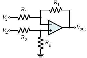
The circuit shown computes the difference
Subtraction
In arithmetic, subtraction is one of the four basic binary operations; it is the inverse of addition, meaning that if we start with any number and add any number and then subtract the same number we added, we return to the number we started with...
of two voltages multiplied by some constant. In particular, the output voltage is:
The differential input impedance Zin (i.e., the impedance between the two input pins) is approximately R1 + R2. The input currents vary with the operating point of the circuit. Consequently, if the two sources feeding this circuit have appreciable output impedance
Output impedance
The output impedance, source impedance, or internal impedance of an electronic device is the opposition exhibited by its output terminals to an alternating current of a particular frequency as a result of resistance, inductance and capacitance...
, then non-linearities can appear in the output. An instrumentation amplifier mitigates these problems.
- Under the condition that the Rf/R1 = Rg/R2, the output expression becomes:
-
 where
where  is the differential gain of the circuit.
- Moreover, the amplifier synthesized with this choice of parameters has good common-mode rejectionCommon-mode rejection ratioThe common-mode rejection ratio of a differential amplifier is the tendency of the devices to reject the input signals common to both input leads...
in theory because components of the signals that have V1 = V2 are not expressed on the output. Although this property is described here with resistances, it is a more general property of the impedances in the circuit. So, for example, if a compensation capacitor is added across any resistor (e.g., to improve phase marginPhase marginIn electronic amplifiers, phase margin is the difference between the phase, measured in degrees, of an amplifier's output signal and 180°, as a function of frequency. The PM is taken as positive at frequencies below where the open-loop phase first crosses 180°, i.e. the signal becomes inverted,...
and ensure closed-loop stabilityBIBO stabilityIn electrical engineering, specifically signal processing and control theory, BIBO stability is a form of stability for linear signals and systems that take inputs. BIBO stands for Bounded-Input Bounded-Output...
of the operational amplifier), similar changes need to be made in the rest of the circuit to maintain the ratio balance. Otherwise, high-frequency components common to both V1 and V2 can express themselves on the output. Additionally, because of leakageLeakage (electronics)In electronics, leakage may refer to a gradual loss of energy from a charged capacitor. It is primarily caused by electronic devices attached to the capacitors, such as transistors or diodes, which conduct a small amount of current even when they are turned off...
or bias currents in a real operational amplifier, it is usually desirable for the impedance looking out each input to the operational amplifier to be equal to the impedance looking out of the other input of the operational amplifier. Otherwise, the same current into each operational amplifier input will generate a parasitic differential signal and thus a parasitic output component. Consequently, choosing R1 = R2 and Rf = Rg is common in practice.
- In the special case when Rf/R1 = Rg/R2, as before, and Rf = R1, the differential gain A = 1, and the circuit is a differential follower with:

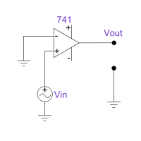
Voltage follower (Unity Buffer Amplifier)
Used as a buffer amplifier
Buffer amplifier
A buffer amplifier is one that provides electrical impedance transformation from one circuit to another...
to eliminate loading effects (e.g., connecting a device with a high source impedance to a device with a low input impedance
Input impedance
The input impedance of an electrical network is the equivalent impedance "seen" by a power source connected to that network. If the source provides known voltage and current, such impedance can be calculated using Ohm's Law...
).
(realistically, the differential input impedance of the op-amp itself, 1 MΩ to 1 TΩ)Due to the strong (i.e., unity gain) feedback and certain non-ideal characteristics of real operational amplifiers, this feedback system is prone to have poor stability margin
Phase margin
In electronic amplifiers, phase margin is the difference between the phase, measured in degrees, of an amplifier's output signal and 180°, as a function of frequency. The PM is taken as positive at frequencies below where the open-loop phase first crosses 180°, i.e. the signal becomes inverted,...
s. Consequently, the system may be unstable
BIBO stability
In electrical engineering, specifically signal processing and control theory, BIBO stability is a form of stability for linear signals and systems that take inputs. BIBO stands for Bounded-Input Bounded-Output...
when connected to sufficiently capacitive loads. In these cases, a lag compensation
Frequency compensation
In electrical engineering, frequency compensation is a technique used in amplifiers, and especially in amplifiers employing negative feedback. It usually has two primary goals: To avoid the unintentional creation of positive feedback, which will cause the amplifier to oscillate, and to control...
network (e.g., connecting the load to the voltage follower through a resistor) can be used to restore stability. The manufacturer data sheet for the operational amplifier may provide guidance for the selection of components in external compensation networks. Alternatively, another operational amplifier can be chosen that has more appropriate internal compensation.
Summing amplifier
- When
 , and
, and  independent
- When

- Output is inverted
- Input impedance of the nth input is
 (
( is a virtual groundVirtual groundVirtual ground is a node of the circuit that is maintained at a steady reference potential, without being connected directly to the reference potential...
)
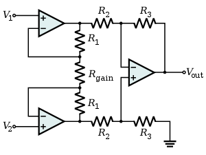
Instrumentation amplifier
Combines very high input impedance
Input impedance
The input impedance of an electrical network is the equivalent impedance "seen" by a power source connected to that network. If the source provides known voltage and current, such impedance can be calculated using Ohm's Law...
, high common-mode rejection, low DC offset, and other properties used in making very accurate, low-noise measurements
- Is made by adding a non-inverting bufferBuffer amplifierA buffer amplifier is one that provides electrical impedance transformation from one circuit to another...
to each input of the differential amplifier to increase the input impedance.
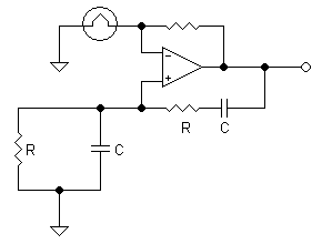
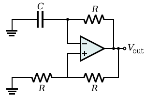
Wien bridge oscillator
Produces a very low distortion sine wave
Sine wave
The sine wave or sinusoid is a mathematical function that describes a smooth repetitive oscillation. It occurs often in pure mathematics, as well as physics, signal processing, electrical engineering and many other fields...
. Uses negative temperature compensation in the form of a light bulb or diode.
Relaxation oscillator
By using an RC network to add slow negative feedback
Negative feedback
Negative feedback occurs when the output of a system acts to oppose changes to the input of the system, with the result that the changes are attenuated. If the overall feedback of the system is negative, then the system will tend to be stable.- Overview :...
to the inverting Schmitt trigger, a relaxation oscillator
Relaxation oscillator
A relaxation oscillator is an oscillator based upon the behavior of a physical system's return to equilibrium after being disturbed. That is, a dynamical system within the oscillator continuously dissipates its internal energy...
is formed. The feedback through the RC network causes the Schmitt trigger output to oscillate in an endless symmetric square wave
Square wave
A square wave is a kind of non-sinusoidal waveform, most typically encountered in electronics and signal processing. An ideal square wave alternates regularly and instantaneously between two levels...
(i.e., the Schmitt trigger in this configuration is an astable multivibrator).
Comparator

Bistable
Bistability
Bistability is a fundamental phenomenon in nature. Something that is bistable can be resting in either of two states. These rest states need not be symmetric with respect to stored energy...
output that indicates which of the two inputs has a higher voltage. That is,
where
and are nominally the positive and negative supply voltages (which are not shown in the diagram).Threshold detector
The threshold detector with hysteresis
Hysteresis
Hysteresis is the dependence of a system not just on its current environment but also on its past. This dependence arises because the system can be in more than one internal state. To predict its future evolution, either its internal state or its history must be known. If a given input alternately...
, very similar to the zero crossing threshold detector
Zero crossing threshold detector
200px|thumb|right|Circuit DiagramA zero crossing detector is used for detecting the zero crossings of AC signals. A typical AC signal is the sine wave which goes up and down the zero level. Many electronic systems need to know 'when' the signal crossed the zero level...
, consists of an operational amplifier
Operational amplifier
An operational amplifier is a DC-coupled high-gain electronic voltage amplifier with a differential input and, usually, a single-ended output...
and a series of resistors that provide hysteresis. Like other detectors, this device functions as a voltage
Voltage
Voltage, otherwise known as electrical potential difference or electric tension is the difference in electric potential between two points — or the difference in electric potential energy per unit charge between two points...
switch, but with an important difference. The state of the detector output is not directly affected by input voltage, but instead by the voltage drop across its input terminals (here, referred to as Va). From Kirchhoff's Current Law
Kirchhoff's circuit laws
Kirchhoff's circuit laws are two equalities that deal with the conservation of charge and energy in electrical circuits, and were first described in 1845 by Gustav Kirchhoff...
, this value depends both on Vin and the output voltage of the threshold detector itself, both multiplied by a resistor ratio.
Unlike the zero crossing detector, the detector with hysteresis does not switch when Vin is zero, rather the output becomes Vsat+ when Va becomes positive and Vsat- when Va becomes negative. Further examination of the Va equation reveals that Vin can exceed zero (positive or negative) by a certain magnitude before the output of the detector is caused to switch. By adjusting the value of R1, the magnitude of Vin that will cause the detector to switch can be increased or decreased. This property often proves very useful in various applications, including signal generators.
Zero level detector
- Acts as a comparator with one input tied to ground.
- When input is at zero, op-amp output is zero (assuming split supplies.)
- Zener diode can be used to clipClipper (electronics)In electronics, a clipper is a device designed to prevent the output of a circuit from exceeding a predetermined voltage level without distorting the remaining part of the applied waveform....
output at set levels.
Schmitt trigger
A bistable multivibrator implemented as a comparatorComparator
In electronics, a comparator is a device that compares two voltages or currents and switches its output to indicate which is larger. They are commonly used in devices such as Analog-to-digital converters .- Input voltage range :...
with hysteresis
Hysteresis
Hysteresis is the dependence of a system not just on its current environment but also on its past. This dependence arises because the system can be in more than one internal state. To predict its future evolution, either its internal state or its history must be known. If a given input alternately...
.
In this configuration, the input voltage is applied through the resistor
(which may be the source internal resistance) to the non-inverting input and the inverting input is grounded or referenced. The hysteresis curve is non-inverting and the switching thresholds are where is the greatest output magnitude of the operational amplifier.Alternatively, the input source and the ground may be swapped. Now the input voltage is applied directly to the inverting input and the non-inverting input is grounded or referenced. The hysteresis curve is inverting and the switching thresholds are
. Such a configuration is used in the relaxation oscillator shown below.Inverting integrator
Integral
Integration is an important concept in mathematics and, together with its inverse, differentiation, is one of the two main operations in calculus...
the (inverted) signal over time
(where
and are functions of time, is the output voltage of the integrator at time t = 0.)- Note that this can also be viewed as a low-passLow-pass filterA low-pass filter is an electronic filter that passes low-frequency signals but attenuates signals with frequencies higher than the cutoff frequency. The actual amount of attenuation for each frequency varies from filter to filter. It is sometimes called a high-cut filter, or treble cut filter...
electronic filterElectronic filterElectronic filters are electronic circuits which perform signal processing functions, specifically to remove unwanted frequency components from the signal, to enhance wanted ones, or both...
. It is a filter with a single pole at DC (i.e., where ) and gain.
 - There are several potential problems with this circuit.
- It is usually assumed that the input
 has zero DC component (i.e., has a zero average value). Otherwise, unless the capacitor is periodically discharged, the output will drift outside of the operational amplifier's operating range.
 - Even when
 has no offset, the leakage or bias currents into the operational amplifier inputs can add an unexpected offset voltage to
  that causes the output to drift. Balancing input currents and replacing the non-inverting (
 ) short-circuit to ground with a resistor with resistance
  can reduce the severity of this problem.
 - Because this circuit provides no DC feedback (i.e., the capacitor appears like an open circuit to signals with
 ), the offset of the output may not agree with expectations (i.e.,
  may be out of the designer's control with the present circuit).
- It is usually assumed that the input
- Many of these problems can be made less severe by adding a large resistor
 in parallel with the feedback capacitor. At significantly high frequencies, this resistor will have negligible effect. However, at low frequencies where there are drift and offset problems, the resistor provides the necessary feedback to hold the output steady at the correct value. In effect, this resistor reduces the DC gain of the "integrator" – it goes from infinite to some finite value
  .
.
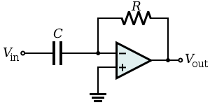
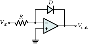
Inverting differentiator
Differentiates
Derivative
In calculus, a branch of mathematics, the derivative is a measure of how a function changes as its input changes. Loosely speaking, a derivative can be thought of as how much one quantity is changing in response to changes in some other quantity; for example, the derivative of the position of a...
the (inverted) signal over time.
- Note that this can also be viewed as a high-passHigh-pass filterA high-pass filter is a device that passes high frequencies and attenuates frequencies lower than its cutoff frequency. A high-pass filter is usually modeled as a linear time-invariant system...
electronic filterElectronic filterElectronic filters are electronic circuits which perform signal processing functions, specifically to remove unwanted frequency components from the signal, to enhance wanted ones, or both...
. It is a filter with a single zero at DC (i.e., where angular frequencyAngular frequencyIn physics, angular frequency ω is a scalar measure of rotation rate. Angular frequency is the magnitude of the vector quantity angular velocity...
 radians) and gain. The high-pass characteristics of a differentiating amplifier (i.e., the low-frequency zero) can lead to stability challenges when the circuit is used in an analog servo loop (e.g., in a PID controllerPID controllerA proportional–integral–derivative controller is a generic control loop feedback mechanism widely used in industrial control systems – a PID is the most commonly used feedback controller. A PID controller calculates an "error" value as the difference between a measured process variable and a...
with a significant derivative gain). In particular, as a root locus analysisRoot locusRoot locus analysis is a graphical method for examining how the roots of a system change with variation of a certain system parameter, commonly the gain of a feedback system. This is a technique used in the field of control systems developed by Walter R...
would show, increasing feedback gain will drive a closed-loop pole toward marginal stability at the DC zero introduced by the differentiator.
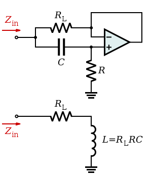
Inductance gyrator
Simulates an inductor
Inductor
An inductor is a passive two-terminal electrical component used to store energy in a magnetic field. An inductor's ability to store magnetic energy is measured by its inductance, in units of henries...
(i.e., provides inductance
Inductance
In electromagnetism and electronics, inductance is the ability of an inductor to store energy in a magnetic field. Inductors generate an opposing voltage proportional to the rate of change in current in a circuit...
without the use of a possibly costly inductor). The circuit exploits the fact that the current flowing through a capacitor behaves through time as the voltage across an inductor. The capacitor used in this circuit is smaller than the inductor it simulates and its capacitance is less subject to changes in value due to environmental changes.
This circuit is unsuitable for applications relying on the back EMF property of an inductor as this will be limited in a gyrator circuit to the voltage supplies of the op-amp.
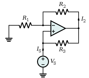
Negative impedance converter (NIC)
Creates a resistor
Resistor
A linear resistor is a linear, passive two-terminal electrical component that implements electrical resistance as a circuit element.The current through a resistor is in direct proportion to the voltage across the resistor's terminals. Thus, the ratio of the voltage applied across a resistor's...
having a negative value for any signal generator
- In this case, the ratio between the input voltage and the input current (thus the input resistance) is given by:
In general, the components
, , and need not be resistors; they can be any component that can be described with an impedanceElectrical impedance
Electrical impedance, or simply impedance, is the measure of the opposition that an electrical circuit presents to the passage of a current when a voltage is applied. In quantitative terms, it is the complex ratio of the voltage to the current in an alternating current circuit...
.
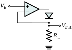
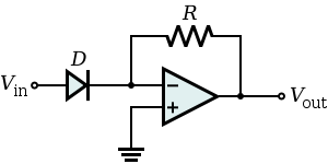
Precision rectifier
The voltage drop VF across the forward biased diode in the circuit of a passive rectifier is undesired. In this active version, the problem is solved by connecting the diode in the negative feedback loop. The op-amp compares the output voltage across the load with the input voltage and increases its own output voltage with the value of VF. As a result, the voltage drop VF is compensated and the circuit behaves very nearly as an ideal (super) diode
Diode
In electronics, a diode is a type of two-terminal electronic component with a nonlinear current–voltage characteristic. A semiconductor diode, the most common type today, is a crystalline piece of semiconductor material connected to two electrical terminals...
with VF = 0 V.
The circuit has speed limitations at high frequency because of the slow negative feedback and due to the low slew rate of many non-ideal op-amps.
Logarithmic output
- The relationship between the input voltage
 and the output voltage
  is given by:
- where
 is the saturation current and
  is the thermal voltage.
- If the operational amplifier is considered ideal, the negative pin is virtually grounded, so the current flowing into the resistor from the source (and thus through the diode to the output, since the op-amp inputs draw no current) is:

- where
 is the current through the diode. As known, the relationship between the current and the voltage for a diodeDiodeIn electronics, a diode is a type of two-terminal electronic component with a nonlinear current–voltage characteristic. A semiconductor diode, the most common type today, is a crystalline piece of semiconductor material connected to two electrical terminals...
is:
- This, when the voltage is greater than zero, can be approximated by:

- Putting these two formulae together and considering that the output voltage is the negative of the voltage across the diode (
 ), the relationship is proven.
Note that this implementation does not consider temperature stability and other non-ideal effects.
Exponential output
- The relationship between the input voltage
 and the output voltage
  is given by:
where
is the saturation currentSaturation current
Saturation current is a term used in relation to semiconductor diodes. It is more fully, and accurately, named reverse saturation current and is "part of the reverse current in a diode caused by diffusion of minority carriers from the neutral regions to the depletion region...
and
is the thermal voltage.- Considering the operational amplifier ideal, then the negative pin is virtually grounded, so the current through the diode is given by:
when the voltage is greater than zero, it can be approximated by:
The output voltage is given by:
See also
- Current-feedback operational amplifierCurrent-feedback operational amplifierThe current feedback operational amplifier otherwise known as CfoA or CfA is a type of electronic amplifier whose inverting input is sensitive to current, rather than to voltage as in a conventional voltage-feedback operational amplifier . The CFA was invented by David Nelson at Comlinear...
- Frequency compensationFrequency compensationIn electrical engineering, frequency compensation is a technique used in amplifiers, and especially in amplifiers employing negative feedback. It usually has two primary goals: To avoid the unintentional creation of positive feedback, which will cause the amplifier to oscillate, and to control...
- Operational amplifierOperational amplifierAn operational amplifier is a DC-coupled high-gain electronic voltage amplifier with a differential input and, usually, a single-ended output...
- Operational transconductance amplifierOperational transconductance amplifierThe operational transconductance amplifier is an amplifier whose differential input voltage produces an output current. Thus, it is a voltage controlled current source . There is usually an additional input for a current to control the amplifier's transconductance...
- Miller theorem applications closely related to the op-amp circuits from this article
Further reading
- Paul Horowitz and Winfield Hill, The Art of Electronics. 2nd ed. Cambridge University Press, Cambridge, 1989 ISBN 0-521-37095-7
- Sergio Franco, Design with Operational Amplifiers and Analog Integrated Circuits, 3rd ed., McGraw-Hill, New York, 2002 ISBN 0-07-232084-2
External links
– Analog DevicesAnalog Devices
Analog Devices, Inc. , known as ADI, is an American multinational semiconductor company specializing in data conversion and signal conditioning technology, headquartered in Norwood, Massachusetts...
Application note – Texas Instruments
Texas Instruments
Texas Instruments Inc. , widely known as TI, is an American company based in Dallas, Texas, United States, which develops and commercializes semiconductor and computer technology...
Application note