

Mechanical advantage
Encyclopedia
Mechanical advantage is a measure of the force amplification achieved by using a tool, mechanical device or machine system. Ideally, the device preserves the input power and simply trades off forces against movement to obtain a desired amplification in the output force. The model for this is the law of the lever
. Machine components designed to manage forces and movement in this way are called mechanism
s.
An ideal mechanism transmits power without adding to or subtracting from it. This means the ideal mechanism does not include a power source, and is frictionless and constructed from rigid bodies that do not deflect or wear. The performance of real systems is obtained from this ideal by using efficiency factors that take into account friction, deformation and wear.
is a movable bar that pivots on a fulcrum attached to the ground. The lever operates by applying forces at different distances from the fulcrum, or pivot.
As the lever rotates around the fulcrum points farther from this pivot move faster than points closer to the pivot. The power into and out of the lever must be the same, so forces applied to points farther from the pivot must be less than when applied to points closer in.
If a and b are distances from the fulcrum to points A and B and let the force FA applied to A is the input and the force FB applied at B is the output, the ratio of the velocities of points A and B is given by a/b, so we have the ratio of the output force to the input force, or mechanical advantage, is given by
This is the law of the lever, which was proven by Archimedes
using geometric reasoning. It shows that if the distance a from the fulcrum to where the input force is applied (point A) is greater than the distance b from fulcrum to where the output force is applied (point B), then the lever amplifies the input force. If the distance from the fulcrum to the input force is less than from the fulcrum to the output force, then the lever reduces the input force.
The use of velocity in the static analysis of a lever is an application of the principle of virtual work
.
Power is the product of force and velocity. The power input to a gear train with a torque TA applied to the drive pulley which rotates at an angular velocity of ωA is P=TAωA.
Because the power flow is constant, the torque TB and angular velocity ωB of the output gear must satisfy the relation
which yields
This shows that for an ideal mechanism the input-output speed ratio equals the mechanical advantage of the system. This applies to all mechanical system
s ranging from robots to linkages
.
.
The velocity v of the point of contact on the pitch circles is the same on both gears, and is given by
where input gear A has radius rA and meshes with output gear B of radius rB,
therefore,
where NA is the number of teeth on the input gear and NB is the number of teeth on the output gear.
The mechanical advantage of a pair of meshing gears for which the input gear has NA teeth and the output gear has NB teeth is given by
This shows that if the output gear GB has more teeth than the input gear GA, then the gear train amplifies the input torque. And, if the output gear has fewer teeth than the input gear, then the gear train reduces the input torque.
If the output gear of a gear train rotates more slowly than the input gear, then the gear train is called a speed reducer. In this case, because the output gear must have more teeth than the input gear, the speed reducer will amplify the input torque.
The velocity v of the chain or belt is the same when in contact with the two sprockets or pulleys:
where the input sprocket or pulley A meshes with the chain or belt along the pitch radius rA and the output sprocket or pulley B meshes with this chain or belt along the pitch radius rB,
therefore
where NA is the number of teeth on the input sprocket and NB is the number of teeth on the output sprocket. For a timing belt drive, the number of teeth on the sprocket can be used. For friction belt drives the pitch radius of the input and output pulleys must be used.
The mechanical advantage of a pair of a chain drive or timing belt drive with an input sprocket with NA teeth and the output sprocket has NB teeth is given by
The mechanical advantage for friction belt drives is given by
Chains and belts dissipate power through friction, stretch and wear, which means the power output is actually less than the power input, which means the mechanical advantage of the real system will be less than that calculated for an ideal mechanism. A chain or belt drive can lose as much as 5% of the power through the system in friction heat, deformation and wear, in which case the efficiency of the drive is 95%.

Now, consider the small and large front sprockets which have 28 and 52 teeth respectively, and consider the small and large rear sprockets which have 16 and 32 teeth each. Using these numbers we can compute the following speed ratios between the front and rear sprockets
The ratio of the force driving the bicycle to the force on the pedal, which is the total mechanical advantage of the bicycle, is the product of the speed ratio and the crank-wheel lever ratio.
Notice that in every case the force on the pedals is greater than the force driving the bicycle forward. This keeps the pedal crank speed low relative to the speed of the drive wheel even at low overall speeds.
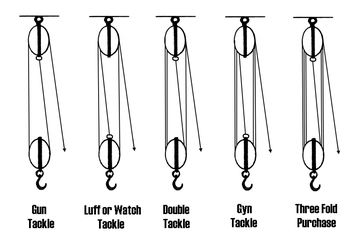
is an assembly of a rope and pulleys that is used to lift loads. A number of pulleys are assembled together to form the blocks, one that is fixed and one that moves with the load. The rope is threaded through the pulleys to provide mechanical advantage that amplifies that force applied to the rope.
In order to determine the mechanical advantage of a block and tackle system consider the simple case of a gun tackle, which has a single mounted, or fixed, pulley and a single movable pulley. The rope is threaded around the fixed block and falls down to the moving block where it is threaded around the pulley and brought back up to be knotted to the fixed block.
 Let S be the distance from the axle of the fixed block to the end of the rope, which is A where the input force is applied. Let R be the distance from the axle of the fixed block to the axle of the moving block, which is B where the load is applied.
The total length of the rope L can written as
where K is the constant length of rope that passes over the pulleys and does not change as the block and tackle moves.
The velocities VA nd VB of the points A and B are related by the constant length of the rope, that is
or
The negative sign shows that the velocity of the load is opposite to the velocity of the applied force, which means as we pull down on the rope the load moves up.
Let VA be positive downwards and VB be positive upwards, so this relationship can be written as the speed ratio
where 2 is the number of rope sections supporting the moving block.
Let FA be the input force applied at A the end of the rope, and let FB be the force at B on the moving block. Like the velocities FA is directed downwards and FB is directed upwards.
For an ideal block and tackle system there is no friction in the pulleys and no deflection or wear in the rope, which means the power input by the applied force FAVA must equal the power out acting on the load FBVB, that is
The ratio of the output force to the input force is the mechanical advantage of an ideal gun tackle system,
This analysis generalizes to an ideal block and tackle with a moving block supported by n rope sections,
This shows that the force exerted by an ideal block and tackle is n times the input force, where n is the number of sections of rope that support the moving block.
, the two equations can be combined, indicating that the force exerted IN to such a machine (denominator of first ratio) multiplied by the distance moved IN (numerator of second ratio) will equal the force exerted OUT of the machine multiplied by the distance moved OUT (i.e., work IN equals work OUT
).
As an ideal example, using a block and tackle
with six ropes, and a 600 pound load, the operator would be required to pull the rope six feet, and exert 100 pounds of force to lift the load one foot. Both equations show that the MA is six. In the first equation, 100 pounds of force IN results in 600 pounds of force OUT. The second equation calculates only the ideal mechanical advantage (IMA) and ignores real world energy
losses due to friction and other causes. Subtracting those losses from the IMA or using the first equation yields the actual mechanical advantage (AMA). The ratio of AMA to IMA is the mechanical efficiency
of the system.
There are two types of mechanical advantage: ideal mechanical advantage (IMA) and actual mechanical advantage (AMA).
. It is calculated using physics principles because no ideal machine actually exists.
The IMA of a machine can be found with the following formula:
where
. Actual mechanical advantage takes into consideration real world factors such as energy lost in friction.
The AMA of a machine is calculated with the following formula:
where
Lever
In physics, a lever is a rigid object that is used with an appropriate fulcrum or pivot point to either multiply the mechanical force that can be applied to another object or resistance force , or multiply the distance and speed at which the opposite end of the rigid object travels.This leverage...
. Machine components designed to manage forces and movement in this way are called mechanism
Mechanism (engineering)
A mechanism is a device designed to transform input forces and movement into a desired set of output forces and movement. Mechanisms generally consist of moving components such as gears and gear trains, belt and chain drives, cam and follower mechanisms, and linkages as well as friction devices...
s.
An ideal mechanism transmits power without adding to or subtracting from it. This means the ideal mechanism does not include a power source, and is frictionless and constructed from rigid bodies that do not deflect or wear. The performance of real systems is obtained from this ideal by using efficiency factors that take into account friction, deformation and wear.
Law of the lever
The leverLever
In physics, a lever is a rigid object that is used with an appropriate fulcrum or pivot point to either multiply the mechanical force that can be applied to another object or resistance force , or multiply the distance and speed at which the opposite end of the rigid object travels.This leverage...
is a movable bar that pivots on a fulcrum attached to the ground. The lever operates by applying forces at different distances from the fulcrum, or pivot.
As the lever rotates around the fulcrum points farther from this pivot move faster than points closer to the pivot. The power into and out of the lever must be the same, so forces applied to points farther from the pivot must be less than when applied to points closer in.
If a and b are distances from the fulcrum to points A and B and let the force FA applied to A is the input and the force FB applied at B is the output, the ratio of the velocities of points A and B is given by a/b, so we have the ratio of the output force to the input force, or mechanical advantage, is given by
This is the law of the lever, which was proven by Archimedes
Archimedes
Archimedes of Syracuse was a Greek mathematician, physicist, engineer, inventor, and astronomer. Although few details of his life are known, he is regarded as one of the leading scientists in classical antiquity. Among his advances in physics are the foundations of hydrostatics, statics and an...
using geometric reasoning. It shows that if the distance a from the fulcrum to where the input force is applied (point A) is greater than the distance b from fulcrum to where the output force is applied (point B), then the lever amplifies the input force. If the distance from the fulcrum to the input force is less than from the fulcrum to the output force, then the lever reduces the input force.
The use of velocity in the static analysis of a lever is an application of the principle of virtual work
Virtual work
Virtual work arises in the application of the principle of least action to the study of forces and movement of a mechanical system. Historically, virtual work and the associated calculus of variations were formulated to analyze systems of rigid bodies, but they have also been developed for the...
.
Speed ratio
The requirement for power input to an ideal mechanism to equal power output provides a simple way to compute mechanical advantage from the input-output speed ratio of the system.Power is the product of force and velocity. The power input to a gear train with a torque TA applied to the drive pulley which rotates at an angular velocity of ωA is P=TAωA.
Because the power flow is constant, the torque TB and angular velocity ωB of the output gear must satisfy the relation
which yields
This shows that for an ideal mechanism the input-output speed ratio equals the mechanical advantage of the system. This applies to all mechanical system
Mechanical system
A mechanical system manages power to accomplish a task that involves forces and movement. Mechanical is derived from the Latin word machina, which in turn derives from the Doric Greek μαχανά , Ionic Greek μηχανή "contrivance, machine, engine" and that from μῆχος , "means, expedient, remedy".The...
s ranging from robots to linkages
Linkage (mechanical)
A mechanical linkage is an assembly of bodies connected together to manage forces and movement. The movement of a body, or link, is studied using geometry so the link is considered to be rigid. The connections between links are modeled as providing ideal movement, pure rotation or sliding for...
.
Gear trains
Gear teeth are designed so that the number of teeth on a gear is proportional to the radius of its pitch circle, and so that the pitch circles of meshing gears roll on each other without slipping. The speed ratio for a pair of meshing gears can be computed from ratio of the radii of the pitch circles and the ratio of the number of teeth on each gear, its gear ratioGear ratio
The gear ratio of a gear train is the ratio of the angular velocity of the input gear to the angular velocity of the output gear, also known as the speed ratio of the gear train. The gear ratio can be computed directly from the numbers of teeth of the various gears that engage to form the gear...
.
The velocity v of the point of contact on the pitch circles is the same on both gears, and is given by
where input gear A has radius rA and meshes with output gear B of radius rB,
therefore,
where NA is the number of teeth on the input gear and NB is the number of teeth on the output gear.
The mechanical advantage of a pair of meshing gears for which the input gear has NA teeth and the output gear has NB teeth is given by
This shows that if the output gear GB has more teeth than the input gear GA, then the gear train amplifies the input torque. And, if the output gear has fewer teeth than the input gear, then the gear train reduces the input torque.
If the output gear of a gear train rotates more slowly than the input gear, then the gear train is called a speed reducer. In this case, because the output gear must have more teeth than the input gear, the speed reducer will amplify the input torque.
Chain and belt drives
Mechanisms consisting of two sprockets connected by a chain, or two pulleys connected by a belt are designed to provide a specific mechanical advantage in a power transmission systems.The velocity v of the chain or belt is the same when in contact with the two sprockets or pulleys:
where the input sprocket or pulley A meshes with the chain or belt along the pitch radius rA and the output sprocket or pulley B meshes with this chain or belt along the pitch radius rB,
therefore
where NA is the number of teeth on the input sprocket and NB is the number of teeth on the output sprocket. For a timing belt drive, the number of teeth on the sprocket can be used. For friction belt drives the pitch radius of the input and output pulleys must be used.
The mechanical advantage of a pair of a chain drive or timing belt drive with an input sprocket with NA teeth and the output sprocket has NB teeth is given by
The mechanical advantage for friction belt drives is given by
Chains and belts dissipate power through friction, stretch and wear, which means the power output is actually less than the power input, which means the mechanical advantage of the real system will be less than that calculated for an ideal mechanism. A chain or belt drive can lose as much as 5% of the power through the system in friction heat, deformation and wear, in which case the efficiency of the drive is 95%.
Example bicycle chain drive
Consider the 18-speed bicycle with 7in cranks and 26in wheels. If the sprockets at the crank and at the rear drive wheel are the same size, then the ratio of the output force on the tire to the input force on the pedal can be calculated from the law of the lever to beNow, consider the small and large front sprockets which have 28 and 52 teeth respectively, and consider the small and large rear sprockets which have 16 and 32 teeth each. Using these numbers we can compute the following speed ratios between the front and rear sprockets
| input (small) | input (large) | output (small) | output (large) | speed ratio | crank-wheel ratio | total MA | |
|---|---|---|---|---|---|---|---|
| low speed | 28 | - | - | 32 | 1.14 | 0.54 | 0.62 |
| mid 1 | - | 52 | - | 32 | 0.62 | 0.54 | 0.33 |
| mid 2 | 28 | - | 16 | - | 0.57 | 0.54 | 0.31 |
| high speed | - | 52 | 16 | - | 0.30 | 0.54 | 0.16 |
The ratio of the force driving the bicycle to the force on the pedal, which is the total mechanical advantage of the bicycle, is the product of the speed ratio and the crank-wheel lever ratio.
Notice that in every case the force on the pedals is greater than the force driving the bicycle forward. This keeps the pedal crank speed low relative to the speed of the drive wheel even at low overall speeds.
Block and tackle
A block and tackleBlock and tackle
A block and tackle is a system of two or more pulleys with a rope or cable threaded between them, usually used to lift or pull heavy loads.The pulleys are assembled together to form blocks so that one is fixed and one moves with the load...
is an assembly of a rope and pulleys that is used to lift loads. A number of pulleys are assembled together to form the blocks, one that is fixed and one that moves with the load. The rope is threaded through the pulleys to provide mechanical advantage that amplifies that force applied to the rope.
In order to determine the mechanical advantage of a block and tackle system consider the simple case of a gun tackle, which has a single mounted, or fixed, pulley and a single movable pulley. The rope is threaded around the fixed block and falls down to the moving block where it is threaded around the pulley and brought back up to be knotted to the fixed block.
The total length of the rope L can written as
where K is the constant length of rope that passes over the pulleys and does not change as the block and tackle moves.
The velocities VA nd VB of the points A and B are related by the constant length of the rope, that is
or
The negative sign shows that the velocity of the load is opposite to the velocity of the applied force, which means as we pull down on the rope the load moves up.
Let VA be positive downwards and VB be positive upwards, so this relationship can be written as the speed ratio
where 2 is the number of rope sections supporting the moving block.
Let FA be the input force applied at A the end of the rope, and let FB be the force at B on the moving block. Like the velocities FA is directed downwards and FB is directed upwards.
For an ideal block and tackle system there is no friction in the pulleys and no deflection or wear in the rope, which means the power input by the applied force FAVA must equal the power out acting on the load FBVB, that is
The ratio of the output force to the input force is the mechanical advantage of an ideal gun tackle system,
This analysis generalizes to an ideal block and tackle with a moving block supported by n rope sections,
This shows that the force exerted by an ideal block and tackle is n times the input force, where n is the number of sections of rope that support the moving block.
Efficiency
For an ideal machineIdeal machine
The term ideal machine refers to a mechanical system in which energy and power are not lost or dissipated through friction, deformation, wear, or other inefficiencies...
, the two equations can be combined, indicating that the force exerted IN to such a machine (denominator of first ratio) multiplied by the distance moved IN (numerator of second ratio) will equal the force exerted OUT of the machine multiplied by the distance moved OUT (i.e., work IN equals work OUT
Work output
In physics, work output is the work done by a simple machine, compound machine, or any type of engine model. In common terms, it is the energy output, which for simple machines is always less than the energy input, even though the forces may be drastically different.In thermodynamics, work output...
).
As an ideal example, using a block and tackle
Block and tackle
A block and tackle is a system of two or more pulleys with a rope or cable threaded between them, usually used to lift or pull heavy loads.The pulleys are assembled together to form blocks so that one is fixed and one moves with the load...
with six ropes, and a 600 pound load, the operator would be required to pull the rope six feet, and exert 100 pounds of force to lift the load one foot. Both equations show that the MA is six. In the first equation, 100 pounds of force IN results in 600 pounds of force OUT. The second equation calculates only the ideal mechanical advantage (IMA) and ignores real world energy
Energy
In physics, energy is an indirectly observed quantity. It is often understood as the ability a physical system has to do work on other physical systems...
losses due to friction and other causes. Subtracting those losses from the IMA or using the first equation yields the actual mechanical advantage (AMA). The ratio of AMA to IMA is the mechanical efficiency
Mechanical efficiency
Mechanical efficiency measures the effectiveness of a machine in transforming the energy and power that is input to the device into an output force and movement...
of the system.
There are two types of mechanical advantage: ideal mechanical advantage (IMA) and actual mechanical advantage (AMA).
Ideal mechanical advantage
The ideal mechanical advantage (IMA), or theoretical mechanical advantage, is the mechanical advantage of an ideal machineIdeal machine
The term ideal machine refers to a mechanical system in which energy and power are not lost or dissipated through friction, deformation, wear, or other inefficiencies...
. It is calculated using physics principles because no ideal machine actually exists.
The IMA of a machine can be found with the following formula:
where
- DE equals the 'effort distance' (for a leverLeverIn physics, a lever is a rigid object that is used with an appropriate fulcrum or pivot point to either multiply the mechanical force that can be applied to another object or resistance force , or multiply the distance and speed at which the opposite end of the rigid object travels.This leverage...
, the distance from the fulcrum to where the effort is applied) - DR equals the resistance distance (for a lever, the distance from the fulcrum to where the resistance is encountered)
Actual mechanical advantage
The actual mechanical advantage (AMA) is the mechanical advantage of a real machineSimple machine
A simple machine is a mechanical device that changes the direction or magnitude of a force.In general, they can be defined as the simplest mechanisms that use mechanical advantage to multiply force. A simple machine uses a single applied force to do work against a single load force...
. Actual mechanical advantage takes into consideration real world factors such as energy lost in friction.
The AMA of a machine is calculated with the following formula:
where
- R = resistance forceResistance forceIn physics, resistance force is the force which an effort force must overcome in order to do work on an object via a simple machine. Resistance force, like most other forces, is measured in newtons or in pounds-force....
obtained from the machine - Eactual = actual effort force applied to the machine
See also
- Outline of machines
- LeverLeverIn physics, a lever is a rigid object that is used with an appropriate fulcrum or pivot point to either multiply the mechanical force that can be applied to another object or resistance force , or multiply the distance and speed at which the opposite end of the rigid object travels.This leverage...
- Simple MachineSimple machineA simple machine is a mechanical device that changes the direction or magnitude of a force.In general, they can be defined as the simplest mechanisms that use mechanical advantage to multiply force. A simple machine uses a single applied force to do work against a single load force...
- Mechanical advantage deviceMechanical advantage deviceA simple machine that exhibit mechanical advantage is called a mechanical advantage device - e.g.:* Lever: The beam shown is in static equilibrium around the fulcrum. This is due to the moment created by vector force "A" counterclockwise being in equilibrium with the moment created by vector force...
- Gear ratioGear ratioThe gear ratio of a gear train is the ratio of the angular velocity of the input gear to the angular velocity of the output gear, also known as the speed ratio of the gear train. The gear ratio can be computed directly from the numbers of teeth of the various gears that engage to form the gear...
- Chain driveChain driveChain drive is a way of transmitting mechanical power from one place to another. It is often used to convey power to the wheels of a vehicle, particularly bicycles and motorcycles...
- Timing beltTiming beltA timing belt, or cam belt , is a part of an internal combustion engine that controls the timing of the engine's valves. Some engines, such as the flat-4 Volkswagen air-cooled engine, and the straight-6 Toyota F engine use timing gears...
- Belt (mechanical)Belt (mechanical)A belt is a loop of flexible material used to link two or more rotating shafts mechanically. Belts may be used as a source of motion, to transmit power efficiently, or to track relative movement. Belts are looped over pulleys. In a two pulley system, the belt can either drive the pulleys in the...
- Roller chainRoller chainRoller chain or bush roller chain is the type of chain drive most commonly used for transmission of mechanical power on many kinds of domestic, industrial and agricultural machinery, including conveyors, wire and tube drawing machines, printing presses, cars, motorcycles, and simple machines like...
- Bicycle chainBicycle chainA bicycle chain is a roller chain that transfers power from the pedals to the drive-wheel of a bicycle, thus propelling it. Most bicycle chains are made from plain carbon or alloy steel, but some are nickel-plated to prevent rust, or simply for aesthetics. Nickel also confers a measure of...
- Bicycle gearingBicycle gearingA bicycle gear or gear ratio refers to the rate at which the rider's legs turn compared to the rate at which the wheels turn. Bicycle gearing refers to how the gear ratio is set or changed. On some bicycles, there is only one gear so the ratio is fixed. Most modern bicycles have multiple gears,...
- Transmission (mechanics)Transmission (mechanics)A machine consists of a power source and a power transmission system, which provides controlled application of the power. Merriam-Webster defines transmission as: an assembly of parts including the speed-changing gears and the propeller shaft by which the power is transmitted from an engine to a...