

Linkage (mechanical)
Encyclopedia
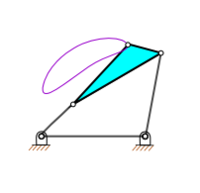
A mechanical linkage is an assembly of bodies connected together to manage forces and movement. The movement of a body, or link, is studied using geometry so the link is considered to be rigid. The connections between links are modeled as providing ideal movement, pure rotation or sliding for example, and are called joints. A linkage modeled as a network of rigid links and ideal joints is called a kinematic chain
.
Linkages may be constructed from open chains, closed chains, or a combination of open and closed chains. Each link in a chain is connected by a joint to one or more other links. Thus, a kinematic chain can be modeled as a graph in which the links are vertices and the joints are paths, which is called a linkage graph.
 The movement of an ideal joint is generally associated with a subgroup of the group of Euclidean displacements. The number of parameters in the subgroup is called the degrees of freedom (DOF) of the joint.
Mechanical linkages are usually designed to transform a given input force and movement into a desired output force and movement. The ratio of the output force to the input force is known as the mechanical advantage
of the linkage, while the ratio of the input speed to the output speed is known as the speed ratio. The speed ratio and mechanical advantage are defined so they yield the same number in an ideal linkage.
A kinimatic chain in which one link is fixed or stationary is called a mechanism, and a linkage designed to be stationary is called a structure.
 Perhaps the simplest linkage is the lever
, which is a link that pivots around a fulcrum
attached to ground, or a fixed point. As a force rotates the lever, points far from the fulcrum have a greater velocity than points near the fulcrum. Because power
in to the lever equals the power out, a small force applied at a point far from the fulcrum (with greater velocity) equals a larger force applied at a point near the fulcrum (with less velocity). The amount the force is amplified is called mechanical advantage
. This is the law of the lever.
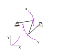
Two levers connected by a rod so that a force applied to one is transmitted to the second is known as a four-bar linkage. The levers are called cranks
, and the fulcrums are called pivots. The connecting rod is also called the coupler. The fourth bar in this assembly is the ground, or frame, on which the cranks are mounted.
Linkages are important components of machines
and tool
s. Examples range from the four-bar linkage used to amplify force in a bolt cutter or to provide independent suspension
in an automobile, to complex linkage systems in robotic arms
and walking machines. The internal combustion engine uses a slider-crank four-bar linkage formed from it piston, connecting rod, and crankshaft to transform power from expanding burning gases into rotary power. Relatively simple linkages are often used to perform complicated tasks.
Interesting examples of linkages include the windshield wiper, the bicycle suspension
, and hydraulic actuators
for heavy equipment. In these examples the components in the linkage move in parallel planes and are called "planar linkages." A linkage with at least one link that moves in three dimensional space is called a "spatial linkage." The skeletons of robotic systems are examples of spatial linkages. The geometric design of these systems relies on modern computer aided design software.
The 4-bar linkage is an adapted mechanical linkage used on bicycles. With a normal full-suspension bike the back wheel moves in a very tight arc shape. This means that more power is lost when going uphill. With a bike fitted with a 4-bar linkage, the wheel moves in such a large arc that it is moving almost vertically. This way the power loss is reduced by up to 30%.
were the primary sources of machine theory. It was Leonardo da Vinci
who brought an inventive energy to machines and mechanism.
In the mid-1700s the steam engine
was of growing importance, and James Watt
realized that efficiency could be increased by using different cylinders for expansion and condensation of the steam. This drove his search for a linkage that could transform rotation of a crank into a linear slide, and resulted in his discovery of what is called Watt's linkage
. This led to the study of linkages that could generate straight lines, even if only approximately; and inspired the mathematician J. J. Sylvester, who lectured on the Peaucellier linkage, which generates an exact straight line from a rotating crank.
The work of Sylvester inspired A. B. Kempe
, who showed that linkages for addition and multiplication could be assembled into a system that traced a given algebraic curve. Kempe's design procedure has inspired research at the intersection of geometry and computer science.
In the late 1800s F. Reuleaux
and A. B. W. Kennedy and L. Burmester
formalized the analysis and synthesis of linkage systems using descriptive geometry
, and P.L.Chebyshev
introduced analytical techniques for the study and invention of linkages.
In the mid 1900's F. Freudenstein and G. N. Sandor used the newly developed digital computer to solve the loop equations of a linkage and determine its dimensions for a desired function, initiating the computer-aided design of linkages. Within two decades these computer techniques were integral to the analysis of complex machine systems and the control of robot manipulators.
R.E.Kaufman combined the computer’s ability to rapidly compute the roots of polynomial equations with a graphical user interface to unite Freudenstein’s techniques with the geometrical methods of Reuleaux and Burmester
and form KINSYN, an interactive computer graphics system for linkage design
The modern study of linkages includes the analysis and design of articulated systems that appear in robots, machine tools, and cable driven and tensegrity systems. These techniques are also being applied to biological systems and even the study of proteins.
A system of n rigid bodies moving in space has 6n degrees of freedom measured relative to a fixed frame. Include this frame in the count of bodies, so that mobility is independent of the choice of the fixed frame, then we have M=6(N-1), where N=n+1 is the number of moving bodies plus the fixed body.
Joints that connect bodies in this system remove degrees of freedom and reduce mobility. Specifically, hinges and sliders each impose five constraints and therefore remove five degrees of freedom. It is convenient to define the number of constraints c that a joint imposes in terms of the joint's freedom f, where c=6-f. In the case of a hinge or slider, which are one degree of freedom joints, we have f=1 and therefore c=6-1=5.
Thus, the mobility of a linkage system formed from n moving links and j joints each with fi, i=1, ..., j, degrees of freedom can be computed as,
where N includes the fixed link. This is known as Kutzbach-Gruebler's equation
There are two important special cases: (i) a simple open chain, and (ii) a simple closed chain. A single open chain consists of n moving links connected end to end by j joints, with one end connected to a ground link. Thus, in this case N=j+1 and the mobility of the chain is
For a simple closed chain, n moving links are connected end-toend by n+1 joints such that the two ends are connected to the ground link forming a loop. In this case, we have N=j and the mobility of the chain is
An example of a simple open chain is a serial robot manipulator. These robotic systems are constructed from a series of links connected by six one degree-of-freedom revolute or prismatic joints, so the system has six degrees of freedom.
An example of a simple closed chain is the RSSR spatial four-bar linkage. The sum of the freedom of these joints is eight, so the mobility of the linkage is two, where one of the degrees of freedom is the rotation of the coupler around the line joining the two S joints.
 In this case, the mobility formula is given by
and we have the special cases,
An example of a planar simple closed chain is the planar four-bar linkage, which is a four-bar loop with four one degree-of-freedom joints and therefore has mobility M=1.
, or hinged, joint denoted by an R, and the prismatic
, or sliding, joint denoted by a P. Most all other joints used for spatial linkages are modeled as combinations of revolute and prismatic joints. For example,
Freudenstein introduced a method to use these equations for the design of a planar four-bar linkage to achieve a specified relation between the input parameters and the configuration of the linkage. Another approach to planar four-bar linkage design was introduced by L. Burmester
, and is called Burmester theory.
or
This formula shows that the linkage must have an even number of links, so we have
See Sunkari and Schmidt for the number of 14- and 16-bar topologies, as well as the number of linkages that have two, three and four degrees-of-freedom.
The planar four-bar linkage is probably the simplest and most common linkage. It is a one degree-of-freedom system that transforms an input crank rotation or slider displacement into and output rotation or slide.
 Examples of four-bar linkages are:
Straight line mechanism
s of the knee.
An important difference between biological and engineering linkages is that revolving bars are rare in biology and that usually only a small range of the theoretically possible is possible due to additional mechanical constraints (especially the necessity to deliver blood). Biological linkages frequently are compliant
. Often one or more bars are formed by ligaments, and often the linkages are three-dimensional. Coupled linkage systems are known, as well as five-, six-, and even seven-bar linkages. Four-bar linkages are by far the most common though.
Linkages can be found in joints, such as the knee
of tetrapods, the hock of sheep, and the cranial mechanism of birds and reptiles. The latter is responsible for the upward motion of the upper bill in many birds.
Linkage mechanisms are especially frequent and manifold in the head of bony fishes, such as wrasses, which have evolved
many specialized feeding mechanisms
. Especially advanced are the linkage mechanisms of jaw protrusion. For suction feeding a system of linked four-bar linkages is responsible for the coordinated opening of the mouth and 3-D expansion of the buccal cavity. Other linkages are responsible for protrusion of the premaxilla
.
Linkages are also present as locking mechanisms, such as in the knee of the horse, which enables the animal to sleep standing, without active muscle contraction. In pivot feeding, a four-bar linkage at first locks the head in a ventrally bent position by the alignment of two bars. The release of the locking mechanism jets the head up and moves the mouth toward the prey within 5-10 ms.
Kinematic chain
A kinematic chain is the assembly of several kinematic pairs connecting rigid body segments. The complexity of the chain is determined by the following factors:...
.
Linkages may be constructed from open chains, closed chains, or a combination of open and closed chains. Each link in a chain is connected by a joint to one or more other links. Thus, a kinematic chain can be modeled as a graph in which the links are vertices and the joints are paths, which is called a linkage graph.
Mechanical linkages are usually designed to transform a given input force and movement into a desired output force and movement. The ratio of the output force to the input force is known as the mechanical advantage
Mechanical advantage
Mechanical advantage is a measure of the force amplification achieved by using a tool, mechanical device or machine system. Ideally, the device preserves the input power and simply trades off forces against movement to obtain a desired amplification in the output force...
of the linkage, while the ratio of the input speed to the output speed is known as the speed ratio. The speed ratio and mechanical advantage are defined so they yield the same number in an ideal linkage.
A kinimatic chain in which one link is fixed or stationary is called a mechanism, and a linkage designed to be stationary is called a structure.
Uses
Lever
In physics, a lever is a rigid object that is used with an appropriate fulcrum or pivot point to either multiply the mechanical force that can be applied to another object or resistance force , or multiply the distance and speed at which the opposite end of the rigid object travels.This leverage...
, which is a link that pivots around a fulcrum
Fulcrum
Fulcrum is the support about which a lever pivots. It may also refer to:* Fulcrum , part of a percussionist's grip* MiG-29 Fulcrum, a Soviet fighter aircraftIn fiction:...
attached to ground, or a fixed point. As a force rotates the lever, points far from the fulcrum have a greater velocity than points near the fulcrum. Because power
Power (physics)
In physics, power is the rate at which energy is transferred, used, or transformed. For example, the rate at which a light bulb transforms electrical energy into heat and light is measured in watts—the more wattage, the more power, or equivalently the more electrical energy is used per unit...
in to the lever equals the power out, a small force applied at a point far from the fulcrum (with greater velocity) equals a larger force applied at a point near the fulcrum (with less velocity). The amount the force is amplified is called mechanical advantage
Mechanical advantage
Mechanical advantage is a measure of the force amplification achieved by using a tool, mechanical device or machine system. Ideally, the device preserves the input power and simply trades off forces against movement to obtain a desired amplification in the output force...
. This is the law of the lever.
Two levers connected by a rod so that a force applied to one is transmitted to the second is known as a four-bar linkage. The levers are called cranks
Crank (mechanism)
A crank is an arm attached at right angles to a rotating shaft by which reciprocating motion is imparted to or received from the shaft. It is used to change circular into reciprocating motion, or reciprocating into circular motion. The arm may be a bent portion of the shaft, or a separate arm...
, and the fulcrums are called pivots. The connecting rod is also called the coupler. The fourth bar in this assembly is the ground, or frame, on which the cranks are mounted.
Linkages are important components of machines
Machine (mechanical)
The mechanical properties of a machine manage power to achieve desired forces and movement. Modern machines often include computers and sensors that monitor performance and plan movement, and are called mechanical systems....
and tool
Tool
A tool is a device that can be used to produce an item or achieve a task, but that is not consumed in the process. Informally the word is also used to describe a procedure or process with a specific purpose. Tools that are used in particular fields or activities may have different designations such...
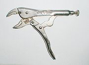
s. Examples range from the four-bar linkage used to amplify force in a bolt cutter or to provide independent suspension
Suspension (vehicle)
Suspension is the term given to the system of springs, shock absorbers and linkages that connects a vehicle to its wheels. Suspension systems serve a dual purpose — contributing to the car's roadholding/handling and braking for good active safety and driving pleasure, and keeping vehicle occupants...
in an automobile, to complex linkage systems in robotic arms
Robot
A robot is a mechanical or virtual intelligent agent that can perform tasks automatically or with guidance, typically by remote control. In practice a robot is usually an electro-mechanical machine that is guided by computer and electronic programming. Robots can be autonomous, semi-autonomous or...
and walking machines. The internal combustion engine uses a slider-crank four-bar linkage formed from it piston, connecting rod, and crankshaft to transform power from expanding burning gases into rotary power. Relatively simple linkages are often used to perform complicated tasks.
Interesting examples of linkages include the windshield wiper, the bicycle suspension
Bicycle suspension
A bicycle suspension is the system or systems used to suspend the rider and all or part of the bicycle in order to protect them from the roughness of the terrain over which they travel...
, and hydraulic actuators
Hydraulic cylinder
A Hydraulic cylinder is a mechanical actuator that is used to give a unidirectional force through a unidirectional stroke. It has many applications, notably in engineering vehicles.- Operation :...
for heavy equipment. In these examples the components in the linkage move in parallel planes and are called "planar linkages." A linkage with at least one link that moves in three dimensional space is called a "spatial linkage." The skeletons of robotic systems are examples of spatial linkages. The geometric design of these systems relies on modern computer aided design software.
The 4-bar linkage is an adapted mechanical linkage used on bicycles. With a normal full-suspension bike the back wheel moves in a very tight arc shape. This means that more power is lost when going uphill. With a bike fitted with a 4-bar linkage, the wheel moves in such a large arc that it is moving almost vertically. This way the power loss is reduced by up to 30%.
History
Archimedes applied geometry to the study of the lever. Into the 1500s the work of Archimedes and Hero of AlexandriaHero of Alexandria
Hero of Alexandria was an ancient Greek mathematician and engineerEnc. Britannica 2007, "Heron of Alexandria" who was active in his native city of Alexandria, Roman Egypt...
were the primary sources of machine theory. It was Leonardo da Vinci
Leonardo da Vinci
Leonardo di ser Piero da Vinci was an Italian Renaissance polymath: painter, sculptor, architect, musician, scientist, mathematician, engineer, inventor, anatomist, geologist, cartographer, botanist and writer whose genius, perhaps more than that of any other figure, epitomized the Renaissance...
who brought an inventive energy to machines and mechanism.
In the mid-1700s the steam engine
Watt steam engine
The Watt steam engine was the first type of steam engine to make use of steam at a pressure just above atmospheric to drive the piston helped by a partial vacuum...
was of growing importance, and James Watt
James Watt
James Watt, FRS, FRSE was a Scottish inventor and mechanical engineer whose improvements to the Newcomen steam engine were fundamental to the changes brought by the Industrial Revolution in both his native Great Britain and the rest of the world.While working as an instrument maker at the...
realized that efficiency could be increased by using different cylinders for expansion and condensation of the steam. This drove his search for a linkage that could transform rotation of a crank into a linear slide, and resulted in his discovery of what is called Watt's linkage
Watt's linkage
Watt's linkage is a type of mechanical linkage invented by James Watt in which the central moving point of the linkage is constrained to travel on an approximation to a straight line...
. This led to the study of linkages that could generate straight lines, even if only approximately; and inspired the mathematician J. J. Sylvester, who lectured on the Peaucellier linkage, which generates an exact straight line from a rotating crank.
The work of Sylvester inspired A. B. Kempe
Alfred Kempe
Sir Alfred Bray Kempe D.C.L. F.R.S. was a mathematician best known for his work on linkages and the four color theorem....
, who showed that linkages for addition and multiplication could be assembled into a system that traced a given algebraic curve. Kempe's design procedure has inspired research at the intersection of geometry and computer science.
In the late 1800s F. Reuleaux
Franz Reuleaux
Franz Reuleaux , was a mechanical engineer and a lecturer of the Berlin Royal Technical Academy, later appointed as the President of the Academy. He was often called the father of kinematics...
and A. B. W. Kennedy and L. Burmester
Ludwig Burmester
Ludwig Ernst Hans Burmester was a German kinematician and geometer.His doctoral thesis Über die Elemente einer Theorie der Isophoten concerned lines on a surface defined by light direction...
formalized the analysis and synthesis of linkage systems using descriptive geometry
Descriptive geometry
Descriptive geometry is the branch of geometry which allows the representation of three-dimensional objects in two dimensions, by using a specific set of procedures. The resulting techniques are important for engineering, architecture, design and in art...
, and P.L.Chebyshev
Pafnuty Chebyshev
Pafnuty Lvovich Chebyshev was a Russian mathematician. His name can be alternatively transliterated as Chebychev, Chebysheff, Chebyshov, Tschebyshev, Tchebycheff, or Tschebyscheff .-Early years:One of nine children, Chebyshev was born in the village of Okatovo in the district of Borovsk,...
introduced analytical techniques for the study and invention of linkages.
In the mid 1900's F. Freudenstein and G. N. Sandor used the newly developed digital computer to solve the loop equations of a linkage and determine its dimensions for a desired function, initiating the computer-aided design of linkages. Within two decades these computer techniques were integral to the analysis of complex machine systems and the control of robot manipulators.
R.E.Kaufman combined the computer’s ability to rapidly compute the roots of polynomial equations with a graphical user interface to unite Freudenstein’s techniques with the geometrical methods of Reuleaux and Burmester
Burmester's theory
Burmester's theory is named after Ludwig Burmester . Burmester introduced geometric techniques for synthesis of linkages in the late 19th century. His approach was to compute the geometric constraints of the linkage directly from the inventor's desired movement for a floating link...
and form KINSYN, an interactive computer graphics system for linkage design
The modern study of linkages includes the analysis and design of articulated systems that appear in robots, machine tools, and cable driven and tensegrity systems. These techniques are also being applied to biological systems and even the study of proteins.
Mobility
The configuration of a system of rigid links connected by ideal joints is defined by a set of configuration parameters, such as the angles around a revolute joint and the slides along prismatic joints measured between adjacent links. The geometric constraints of the linkage allow calculation of all of the configuration parameters in terms of a minimum set, which are the input parameters. The number of input parameters is called the mobility, or degree of freedom, of the linkage system.A system of n rigid bodies moving in space has 6n degrees of freedom measured relative to a fixed frame. Include this frame in the count of bodies, so that mobility is independent of the choice of the fixed frame, then we have M=6(N-1), where N=n+1 is the number of moving bodies plus the fixed body.
Joints that connect bodies in this system remove degrees of freedom and reduce mobility. Specifically, hinges and sliders each impose five constraints and therefore remove five degrees of freedom. It is convenient to define the number of constraints c that a joint imposes in terms of the joint's freedom f, where c=6-f. In the case of a hinge or slider, which are one degree of freedom joints, we have f=1 and therefore c=6-1=5.
Thus, the mobility of a linkage system formed from n moving links and j joints each with fi, i=1, ..., j, degrees of freedom can be computed as,
where N includes the fixed link. This is known as Kutzbach-Gruebler's equation
Chebychev–Grübler–Kutzbach criterion
The Chebychev–Grübler–Kutzbach criterion determines the degree of freedom of a kinematic chain, that is, a coupling of rigid bodies by means of mechanical constraints...
There are two important special cases: (i) a simple open chain, and (ii) a simple closed chain. A single open chain consists of n moving links connected end to end by j joints, with one end connected to a ground link. Thus, in this case N=j+1 and the mobility of the chain is
For a simple closed chain, n moving links are connected end-toend by n+1 joints such that the two ends are connected to the ground link forming a loop. In this case, we have N=j and the mobility of the chain is
An example of a simple open chain is a serial robot manipulator. These robotic systems are constructed from a series of links connected by six one degree-of-freedom revolute or prismatic joints, so the system has six degrees of freedom.
An example of a simple closed chain is the RSSR spatial four-bar linkage. The sum of the freedom of these joints is eight, so the mobility of the linkage is two, where one of the degrees of freedom is the rotation of the coupler around the line joining the two S joints.
Planar and spherical movement
It is common practice to design the linkage system so that the movement of all of the bodies are constrained to lie on parallel planes, to form what is known as a planar linkage. It is also possible to construct the linkage system so that all of the bodies move on concentric spheres, forming a spherical linkage. In both cases, the degrees of freedom of the link is now three rather than six, and the constraints imposed by joints are now c=3-f.and we have the special cases,
- planar or spherical simple open chain,

- planar or spherical simple closed chain,

An example of a planar simple closed chain is the planar four-bar linkage, which is a four-bar loop with four one degree-of-freedom joints and therefore has mobility M=1.
Joints
The most familiar joints for linkage systems are the revoluteRevolute joint
A revolute joint is a one degree of freedom kinematic pair used in mechanisms. Revolute joints provide single-axis rotation function used in many places such as door hinges, folding mechanisms, and other uni-axial rotation devices. -See also:* Cylindrical joint* Kinematics* Degrees of freedom *...
, or hinged, joint denoted by an R, and the prismatic
Prismatic joint
A prismatic joint provides a linear sliding movement between two bodies, and is often called a slider, as in the slider-crank linkage. A prismatic joint is formed with a polygonal cross-section to resist rotation...
, or sliding, joint denoted by a P. Most all other joints used for spatial linkages are modeled as combinations of revolute and prismatic joints. For example,
- the cylindric joint consists of an RP or PR serial chain constructed so that the axes of the revolute and prismatic joints are parallel,
- the spherical joint consists of an RRR serial chain for which each of the hinged joint axes intersect in the same point;
- the planar joint can be constructed either as a planar RRR, RPR, and PPR serial chain that has three degrees-of-freedom.
Analysis and synthesis of linkages
The primary mathematical tool for the analysis of a linkage is known as the kinematics equations of the system. This is a sequence of rigid body transformation along a serial chain within the linkage that locates a floating link relative to the ground frame. Each serial chain within the linkage that connects this floating link to ground provides a set of equations that must be satisfied by the configuration parameters of the system. The result is a set of non-linear equations that define the configuration parameters of the system for a set of values for the input parameters.Freudenstein introduced a method to use these equations for the design of a planar four-bar linkage to achieve a specified relation between the input parameters and the configuration of the linkage. Another approach to planar four-bar linkage design was introduced by L. Burmester
Ludwig Burmester
Ludwig Ernst Hans Burmester was a German kinematician and geometer.His doctoral thesis Über die Elemente einer Theorie der Isophoten concerned lines on a surface defined by light direction...
, and is called Burmester theory.
Planar one degree-of-freedom linkages
The mobility formula provides a way to determine the number of links and joints in a planar linkage that yields a one degree-of-freedom linkage. If we require the mobility of a planar linkage to be M=1 and fi=1, the result isor
This formula shows that the linkage must have an even number of links, so we have
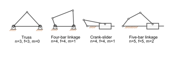
- N=2, j=1: this is a two-bar linkage known as the lever;
- N=4, j=4: this is the four-bar linkage;
- N=6, j=7: this is a six-bar linkageSix-bar linkageA six-bar linkage is a one degree-of-freedom mechanism that is constructed from six links and seven joints. An example is the Klann linkage used to drive the legs of a walking machine....
. A six-bar linkageSix-bar linkageA six-bar linkage is a one degree-of-freedom mechanism that is constructed from six links and seven joints. An example is the Klann linkage used to drive the legs of a walking machine....
two links that have three joints, called ternary links, and there are two topologies of this linkage depending how these links are connected. In the Watt topology, the two ternary are connected by a joint. In the Stephenson topology the two ternary links are connected by binary links; - N=8, j=10: the eight-bar linkage has 16 different topologies;
- N=10, j=13: the 10-bar linkage has 230 different topologies,
- N=12, j=16: the 12-bar has 6856 topologies.
See Sunkari and Schmidt for the number of 14- and 16-bar topologies, as well as the number of linkages that have two, three and four degrees-of-freedom.
The planar four-bar linkage is probably the simplest and most common linkage. It is a one degree-of-freedom system that transforms an input crank rotation or slider displacement into and output rotation or slide.
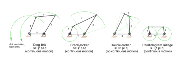
- the crank-rocker, in which the input crank fully rotates and the output link rocks back and forth;
- the slider-drank, in which the input crank rotates and the output slide moves back and forth;
- drag-link mechanisms, in which the input crank fully rotates and drags the output crank in a fully rotational movement.
Other interesting linkages
- PantographPantographA pantograph is a mechanical linkage connected in a special manner based on parallelograms so that the movement of one pen, in tracing an image, produces identical movements in a second pen...
(four-bar, two DOF) - Five bar linkages often have meshing gears for two of the links, creating a one DOF linkage. They can provide greater power transmission with more design flexibility than four-bar linkages.
- Klann linkageKlann LinkageThe Klann linkage is a planar mechanism designed to simulate the gait of legged animal and function as a wheel replacement. The linkage consists of the frame, a crank, two grounded rockers, and two couplers all connected by pivot joints....
is a six-bar linkage that forms the leg of a walking mechanism; - Toggle mechanisms are four-bar linkages that are dimensioned so that they can fold and lock. The linkage is dimensioned so that the linkage reaches a toggle position just before it folds. The high mechanical advantage allows the input crank to deform the linkage just enough push the it beyond the toggle position. This locks the input in place. Toggle mechanisms are used as clamps.
Straight line mechanismStraight line mechanismIn the late seventeenth century, before the development of the planer and the milling machine, it was extremely difficult to machine straight, flat surfaces. For this reason, good prismatic pairs without backlash were not easy to make...
s
- James Watt's parallel motionParallel motionThe parallel motion is a mechanical linkage invented by the Scottish engineer James Watt in 1784 for his double-acting steam engine.In previous engines built by Newcomen and Watt, the piston pulled one end of the walking beam downwards during the power stroke using a chain, and the weight of the...
and Watt's linkageWatt's linkageWatt's linkage is a type of mechanical linkage invented by James Watt in which the central moving point of the linkage is constrained to travel on an approximation to a straight line... - Peaucellier–Lipkin linkage, the first planar linkage to create a straight line output from rotary input; eight-bar, one DOF.
- A Scott Russell linkageScott Russell linkageA Scott Russell linkage converts linear motion, to linear motion in a line perpendicular to the input. These linkages are often used in front wheel drive vehicles with solid rear axles to control lateral movement, as they do not share the disadvantages of the asymmetric Panhard rod and are simpler...
, which converts linear motion, to (almost) linear motion in a line perpendicular to the input. - Chebyshev linkageChebyshev linkageThe Hoekens linkage is a four-bar mechanism that converts rotational motion to approximate straight-line motion. The Hoekens linkage is a cognate linkage of the Chebyshev linkage.-See also:*Straight line mechanism*Peaucellier–Lipkin linkage...
, which provides nearly straight motion of a point with a four-bar linkage. - Hoekens linkage, which provides nearly straight motion of a point with a four-bar linkage.
- Sarrus linkageSarrus linkageThe Sarrus linkage, invented in 1853 by Pierre Frédéric Sarrus, is a mechanical linkage to convert a limited circular motion to a linear motion without reference guideways. The linkage uses two perpendicular hinged rectangular plates positioned parallel over each other...
, which provides motion of one surface in a direction normal to another.
Biological linkages
Linkage systems are widely distributed in animals. The most thorough overview of the different types of linkages in animals has been provided by M. Muller, who also designed a new classification system, which is especially well suited for biological systems. A well-known example is the cruciate ligamentCruciate ligament
Cruciate ligaments are pairs of ligaments arranged like a letter X. They occur in several joints of the body, such as the knee...
s of the knee.
An important difference between biological and engineering linkages is that revolving bars are rare in biology and that usually only a small range of the theoretically possible is possible due to additional mechanical constraints (especially the necessity to deliver blood). Biological linkages frequently are compliant
Compliant mechanism
In mechanical engineering, compliant mechanisms are flexible mechanisms that transfer an input force or displacement to another point through elastic body deformation...
. Often one or more bars are formed by ligaments, and often the linkages are three-dimensional. Coupled linkage systems are known, as well as five-, six-, and even seven-bar linkages. Four-bar linkages are by far the most common though.
Linkages can be found in joints, such as the knee
Cruciate ligament
Cruciate ligaments are pairs of ligaments arranged like a letter X. They occur in several joints of the body, such as the knee...
of tetrapods, the hock of sheep, and the cranial mechanism of birds and reptiles. The latter is responsible for the upward motion of the upper bill in many birds.
Linkage mechanisms are especially frequent and manifold in the head of bony fishes, such as wrasses, which have evolved
Evolution
Evolution is any change across successive generations in the heritable characteristics of biological populations. Evolutionary processes give rise to diversity at every level of biological organisation, including species, individual organisms and molecules such as DNA and proteins.Life on Earth...
many specialized feeding mechanisms
Aquatic predation
Aquatic predation presents a special difficulty as compared to predation on land, because the density of water is about the same as that of the prey, so that the prey tends to be pushed away. This problem was first identified by R.N. Alexander...
. Especially advanced are the linkage mechanisms of jaw protrusion. For suction feeding a system of linked four-bar linkages is responsible for the coordinated opening of the mouth and 3-D expansion of the buccal cavity. Other linkages are responsible for protrusion of the premaxilla
Premaxilla
The incisive bone is the portion of the maxilla adjacent to the incisors. It is a pair of small cranial bones at the very tip of the jaws of many animals, usually bearing teeth, but not always. They are connected to the maxilla and the nasals....
.
Linkages are also present as locking mechanisms, such as in the knee of the horse, which enables the animal to sleep standing, without active muscle contraction. In pivot feeding, a four-bar linkage at first locks the head in a ventrally bent position by the alignment of two bars. The release of the locking mechanism jets the head up and moves the mouth toward the prey within 5-10 ms.
Further reading
— Connections between mathematical and real-world mechanical models, historical development of precision machining, some practical advice on fabricating physical models, with ample illustrations and photographs- Hartenberg, R.S. & J. Denavit (1964) Kinematic synthesis of linkages, New York: McGraw-Hill — Online link from Cornell UniversityCornell UniversityCornell University is an Ivy League university located in Ithaca, New York, United States. It is a private land-grant university, receiving annual funding from the State of New York for certain educational missions...
. — "Linkages: a peculiar fascination" (Chapter 14) is a discussion of mechanical linkage usage in American mathematical education, includes extensive references - How to Draw a Straight Line — Historical discussion of linkage design from Cornell University
External links
- Kinematic Models for Design Digital Library (KMODDL) — Major web resource for kinematics. Movies and photos of hundreds of working mechanical-systems models in the Reuleaux Collection of Mechanisms and Machines at Cornell UniversityCornell UniversityCornell University is an Ivy League university located in Ithaca, New York, United States. It is a private land-grant university, receiving annual funding from the State of New York for certain educational missions...
, plus 5 other major collections. Includes an e-book library of dozens of classic texts on mechanical design and engineering. Includes CAD models and stereolithographic files for selected mechanisms. - How round is your circle? — Supplementary online information to support the book, How round is your circle? : where engineering and mathematics meet, by John Bryant and Chris Sangwin. Includes sections about Watt's and other linkages, many photographs and videos of linkages, errata and elaborations to the published book
- Digital Mechanism and Gear Library (DMG-Lib) (in German: Digitale Mechanismen- und Getriebebibliothek) — Online library about linkages and cams (mostly in German)
- Linkage calculations
- Java animated linkages
- GIF-format animated linkages
- Introductory linkage lecture
- Virtual Mechanisms Animated by Java
- SAM: design, analysis and optimization of (linkage) mechanisms