Function model
Encyclopedia
A function model or functional model in systems engineering
and software engineering
is a structured representation
of the functions
(activities
, actions
, processes, operation
s) within the modeled system
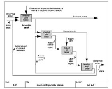
or subject area.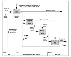 A function model, also called an activity model
or process model, is a graphical representation of an enterprise
's function within a defined scope. The purposes of the function model are to describe the functions and processes, assist with discovery of information needs, help identify opportunities, and establish a basis for determining product and service costs.
was developed in 1896 by Karol Adamiecki
, who called it a harmonogram. Because Adamiecki did not publish his chart until 1931 - and in any case his works were published in either Polish or Russian, languages not popular in the West
- the chart now bears the name of Henry Gantt
(1861–1919), who designed his chart around the years 1910-1915 and popularized it in the West. The first structured method for documenting process flow, the flow process chart
, was introduced by Frank Gilbreth to members of American Society of Mechanical Engineers
(ASME) in 1921 as the presentation “Process Charts—First Steps in Finding the One Best Way”. Gilbreth's tools quickly found their way into industrial engineering
curricula.
One of the first well defined function models, was the Functional Flow Block Diagram
(FFBD) developed by the defense-related TRW
Incorporated in the 1950s. In the 1960s it was exploited by the NASA
to visualize the time sequence of events in a space systems and flight missions. It is further widely used in classical systems engineering
to show the order of execution of system functions.
and software engineering
a function model is created with a functional modeling perspective
. The functional perspective is one of the perspectives possible in business process modelling, other perspecifives are for example behavioural, organisational or informational.
A functional modeling perspective concentrates on describing the dynamic process. The main concept in this modeling perspective is the process, this could be a function, transformation, activity, action, task etc. A well-known example of a modeling language employing this perspective is data flow diagram
s.
The perspective uses four symbols to describe a process, these being:
Now, with these symbols, a process can be represented as a network of these symbols. This decomposed process is a DFD, data flow diagram.
In Dynamic Enterprise Modeling
a division is made in the Control model, Function Model, Process model and Organizational model.
 Functional decomposition
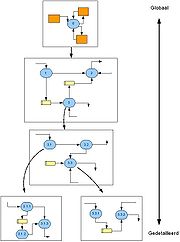
refers broadly to the process of resolving a functional
relationship into its constituent parts in such a way that the original function can be reconstructed from those parts by function composition
. In general, this process of decomposition is undertaken either for the purpose of gaining insight into the identity of the constituent components, or for the purpose of obtaining a compressed representation of the global function, a task which is feasible only when the constituent processes possess a certain level of modularity.
Functional decomposition
has a prominent role in computer programming
, where a major goal is to modularize processes to the greatest extent possible. For example, a library management system may be broken up into an inventory module, a patron information module, and a fee assessment module. In the early decades of computer programming, this was manifested as the "art of subroutining," as it was called by some prominent practitioners.
Functional decomposition of engineering systems is a method for analyzing engineered systems. The basic idea is to try to divide a system in such a way that each block of the block diagram can be described without an "and" or "or" in the description.
This exercise forces each part of the system to have a pure function
. When a system is composed of pure functions, they can be reused, or replaced. A usual side effect is that the interfaces between blocks become simple and generic. Since the interfaces usually become simple, it is easier to replace a pure function with a related, similar function.
 The Functional flow block diagram
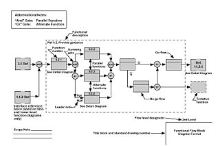
(FFBD) is a multi-tier, time-sequenced, step-by-step flow diagram
of the system
’s functional flow.
The diagram is developed in the 1950s and widely used in classical systems engineering
. The Functional Flow Block Diagram is also referred to as Functional Flow Diagram, functional block diagram, and functional flow.
Functional Flow Block Diagrams (FFBD) usually define the detailed, step-by-step operational and support sequences for system
s, but they are also used effectively to define processes in developing and producing systems. The software development process
es also use FFBDs extensively. In the system context, the functional flow steps may include combinations of hardware
, software, personnel, facilities, and/or procedures. In the FFBD method, the functions are organized and depicted by their logical order of execution. Each function is shown with respect to its logical relationship to the execution and completion of other functions. A node labeled with the function name depicts each function. Arrows from left to right show the order of execution of the functions. Logic symbols represent sequential or parallel execution of functions.
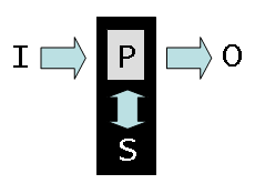 HIPO
HIPO
for hierarchical input process output is a popular 1970s systems analysis
design aid and documentation technique for representing the modules of a system
as a hierarchy
and for documenting each module.
It was used to develop requirements, construct the design, and support implementation of an expert system to demonstrate automated rendezvous. Verification was then conducted systematically because of the method of design and implementation.
The overall design of the system is documented using HIPO charts or structure chart
s. The structure chart is similar in appearance to an organizational chart, but has been modified to show additional detail. Structure charts can be usedto display several types of information, but are used most commonly to diagram either data structure
s or code structures.
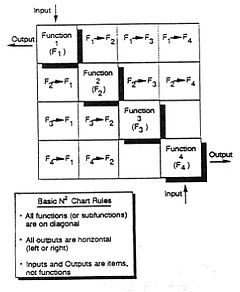 The N2 Chart
is a diagram in the shape of a matrix
, representing functional or physical interfaces between system elements. It is used to systematically identify, define, tabulate, design, and analyze functional and physical interfaces. It applies to system interface
s and hardware
and/or software interfaces.
The N2 diagram has been used extensively to develop data interfaces, primarily in the software areas. However, it can also be used to develop hardware interfaces. The basic N2 chart is shown in Figure 2. The system functions are placed on the diagonal; the remainder of the squares in the N x N matrix represent the interface inputs and outputs.
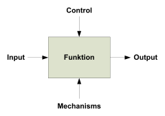 Structured Analysis and Design Technique
(SADT) is a software engineering methodology for describing system
s as a hierarchy of functions, a diagram
matic notation for constructing a sketch for a software application. It offers building blocks to represent entities and activities, and a variety of arrows to relate boxes. These boxes and arrows have an associated informal semantics
. SADT can be used as a functional analysis tool of a given process, using successive levels of details. The SADT method allows to define user needs for IT developments, which is used in industrial Information Systems, but also to explain and to present an activity’s manufacturing processes, procedures.
The SADT supplies a specific functional view of any enterprise by describing the functions and their relationships in a company. These functions fulfill the objectives of a company, such as sales, order planning, product design, part manufacturing, and human resource management. The SADT can depict simple functional relationships and can reflect data and control flow relationships between different functions. The IDEF0
formalism is based on SADT, developed by Douglas T. Ross
in 1985.
 IDEF0
IDEF0
is a function modeling methodology for describing manufacturing
functions, which offers a functional modeling language
for the analysis, development, re-engineering, and integration of information system
s; business processes; or software engineering analysis. It is part of the IDEF
family of modeling languages in the field of software engineering
, and is built on the functional modeling language building SADT
.
The IDEF0 Functional Modeling method is designed to model the decisions, actions, and activities of an organization or system. It was derived from the established graphic modeling language Structured Analysis and Design Technique
(SADT) developed by Douglas T. Ross
and SofTech, Inc.
. In its original form, IDEF0 includes both a definition of a graphical modeling language (syntax
and semantics
) and a description of a comprehensive methodology for developing models. The US Air Force commissioned the SADT developers to develop a function model method for analyzing and communicating the functional perspective of a system. IDEF0 should assist in organizing system analysis and promote effective communication between the analyst and the customer through simplified graphical devices.
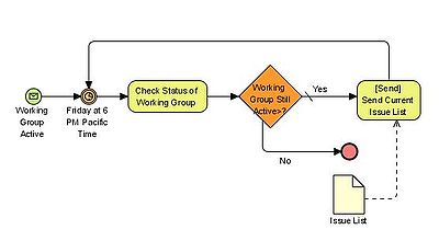 Business Process Model and Notation (BPMN) is a graphical representation for specifying business process
es in a workflow
. BPMN was developed by Business Process Management Initiative (BPMI), and is currently maintained by the Object Management Group
since the two organizations merged in 2005. The current version of BPMN is 2.0.
The Business Process Model and Notation (BPMN) specification provides a graphical notation for specifying business process
es in a Business Process Diagram (BPD). The objective of BPMN is to support business process management for both technical users and business users by providing a notation that is intuitive to business users yet able to represent complex process semantics. The BPMN specification also provides a mapping between the graphics of the notation to the underlying constructs of execution languages, particularly BPEL4WS.
is a top down hierarchical functional decomposition process used as a solution synthesis framework for the analysis, development, re-engineering, and integration of products, information systems, business processes or software engineering solutions. Its structure is suited mathematically to analyze coupling between functions in order to optimize the architectural robustness of potential functional solution models.
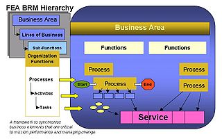
es in the context of the business area functions. The processes in the business function model must be consistent with the processes in the value chain models. Processes are a group of related business activities performed to produce an end product or to provide a service. Unlike business functions that are performed on a continual basis, processes are characterized by the fact that they have a specific beginning and an end point marked by the delivery of a desired output. The figure on the right depicts the relationship between the business processes, business functions, and the business area’s business reference model.
 A Business reference model
is a reference model, concentrating on the functional and organizational aspects of the core business
of an enterprise
, service organization or government agency
. In enterprise engineering a business reference model is part of an Enterprise Architecture Framework or Architecture Framework, which defines how to organize the structure and views
associated with an Enterprise Architecture
.
A reference model
in general is a model of something that embodies the basic goal or idea of something and can then be looked at as a reference for various purposes. A business reference model is a means to describe the business operations
of an organization, independent of the organizational structure
that perform them. Other types of business reference model can also depict the relationship between the business process
es, business functions, and the business area’s business reference model. These reference model can be constructed in layers, and offer a foundation for the analysis of service components, technology, data, and performance.
techniques used by human factors
engineers. An operator function model attempts to represent in mathematical form how an operator might decompose a complex system into simpler parts and coordinate control actions and system configurations so that acceptable overall system performance is achieved. The model represents basic issues of knowledge representation, information flow, and decision making in complex systems. Miller (1985) suggests that the network structure can be thought of as a possible representation of an operator's internal model
of the system plus a control structure which specifies how the model is used to solve the decision problems that comprise operator control functions.
Systems engineering
Systems engineering is an interdisciplinary field of engineering that focuses on how complex engineering projects should be designed and managed over the life cycle of the project. Issues such as logistics, the coordination of different teams, and automatic control of machinery become more...
and software engineering
Software engineering
Software Engineering is the application of a systematic, disciplined, quantifiable approach to the development, operation, and maintenance of software, and the study of these approaches; that is, the application of engineering to software...
is a structured representation
Representation (systemics)
Representation, from the most general and abstract systemic perspective, relates to a role or function or a property of an abstract or real object, relation or changes.For example,* an ambassador or a sport team may represent its nation....
of the functions
Function (engineering)
In engineering, a function is interpreted as a specific process, action or task that a system is able to perform .-In engineering design:In the lifecycle of engineering projects, there are usually distinguished subsequently: Requirements and Functional specification documents. The Requirements...
(activities
Activity diagram
Activity diagrams are graphical representations of workflows of stepwise activities and actions with support for choice, iteration and concurrency. In the Unified Modeling Language, activity diagrams can be used to describe the business and operational step-by-step workflows of components in a system...
, actions
Task analysis
Task analysis is the analysis of how a task is accomplished, including a detailed description of both manual and mental activities, task and element durations, task frequency, task allocation, task complexity, environmental conditions, necessary clothing and equipment, and any other unique factors...
, processes, operation
Operation
Operation may refer to:* Scientific operation* Surgery, or operation* An operation in mathematics:**Unary operation**Binary operation**Arity...
s) within the modeled system
System
System is a set of interacting or interdependent components forming an integrated whole....
or subject area.

Activity diagram
Activity diagrams are graphical representations of workflows of stepwise activities and actions with support for choice, iteration and concurrency. In the Unified Modeling Language, activity diagrams can be used to describe the business and operational step-by-step workflows of components in a system...
or process model, is a graphical representation of an enterprise
Business
A business is an organization engaged in the trade of goods, services, or both to consumers. Businesses are predominant in capitalist economies, where most of them are privately owned and administered to earn profit to increase the wealth of their owners. Businesses may also be not-for-profit...
's function within a defined scope. The purposes of the function model are to describe the functions and processes, assist with discovery of information needs, help identify opportunities, and establish a basis for determining product and service costs.
History
The model originates in the 1950s, after in the first half of the 20th century other types of management diagrams had already been developed. The first known Gantt ChartGantt chart
A Gantt chart is a type of bar chart that illustrates a project schedule. Gantt charts illustrate the start and finish dates of the terminal elements and summary elements of a project. Terminal elements and summary elements comprise the work breakdown structure of the project. Some Gantt charts...
was developed in 1896 by Karol Adamiecki
Karol Adamiecki
-External links:* * *...
, who called it a harmonogram. Because Adamiecki did not publish his chart until 1931 - and in any case his works were published in either Polish or Russian, languages not popular in the West
Western world
The Western world, also known as the West and the Occident , is a term referring to the countries of Western Europe , the countries of the Americas, as well all countries of Northern and Central Europe, Australia and New Zealand...
- the chart now bears the name of Henry Gantt
Henry Gantt
Henry Laurence Gantt, A.B., M.E. was an American mechanical engineer and management consultant who is most famous for developing the Gantt chart in the 1910s....
(1861–1919), who designed his chart around the years 1910-1915 and popularized it in the West. The first structured method for documenting process flow, the flow process chart
Flow process chart
The flow process chart in industrial engineering is a graphical and symbolic representation of the processing activities performed on the work piece.- History :...
, was introduced by Frank Gilbreth to members of American Society of Mechanical Engineers
American Society of Mechanical Engineers
The American Society of Mechanical Engineers is a professional body, specifically an engineering society, focused on mechanical engineering....
(ASME) in 1921 as the presentation “Process Charts—First Steps in Finding the One Best Way”. Gilbreth's tools quickly found their way into industrial engineering
Industrial engineering
Industrial engineering is a branch of engineering dealing with the optimization of complex processes or systems. It is concerned with the development, improvement, implementation and evaluation of integrated systems of people, money, knowledge, information, equipment, energy, materials, analysis...
curricula.
One of the first well defined function models, was the Functional Flow Block Diagram
Functional flow block diagram
A Functional Flow Block Diagram is a multi-tier, time-sequenced, step-by-step flow diagram of a system’s functional flow.The FFBD notation was developed in the 1950s, and is widely used in classical systems engineering...
(FFBD) developed by the defense-related TRW
TRW
TRW Inc. was an American corporation involved in a variety of businesses, mainly aerospace, automotive, and credit reporting. It was a pioneer in multiple fields including electronic components, integrated circuits, computers, software and systems engineering. TRW built many spacecraft,...
Incorporated in the 1950s. In the 1960s it was exploited by the NASA
NASA
The National Aeronautics and Space Administration is the agency of the United States government that is responsible for the nation's civilian space program and for aeronautics and aerospace research...
to visualize the time sequence of events in a space systems and flight missions. It is further widely used in classical systems engineering
Systems engineering
Systems engineering is an interdisciplinary field of engineering that focuses on how complex engineering projects should be designed and managed over the life cycle of the project. Issues such as logistics, the coordination of different teams, and automatic control of machinery become more...
to show the order of execution of system functions.
Functional perspective
In systems engineeringSystems engineering
Systems engineering is an interdisciplinary field of engineering that focuses on how complex engineering projects should be designed and managed over the life cycle of the project. Issues such as logistics, the coordination of different teams, and automatic control of machinery become more...
and software engineering
Software engineering
Software Engineering is the application of a systematic, disciplined, quantifiable approach to the development, operation, and maintenance of software, and the study of these approaches; that is, the application of engineering to software...
a function model is created with a functional modeling perspective
Modeling perspectives
A modeling perspective in information systems is a particular way to represent pre-selected aspects of a system. Any perspective has a different focus, conceptualization, dedication and visualization of what the model is representing....
. The functional perspective is one of the perspectives possible in business process modelling, other perspecifives are for example behavioural, organisational or informational.
A functional modeling perspective concentrates on describing the dynamic process. The main concept in this modeling perspective is the process, this could be a function, transformation, activity, action, task etc. A well-known example of a modeling language employing this perspective is data flow diagram
Data flow diagram
A data flow diagram is a graphical representation of the "flow" of data through an information system, modelling its process aspects. Often they are a preliminary step used to create an overview of the system which can later be elaborated...
s.
The perspective uses four symbols to describe a process, these being:
- Process: Illustrates transformation from input to output.
- Store: Data-collection or some sort of material.
- Flow: Movement of data or material in the process.
- External Entity: External to the modeled system, but interacts with it.
Now, with these symbols, a process can be represented as a network of these symbols. This decomposed process is a DFD, data flow diagram.
In Dynamic Enterprise Modeling
Dynamic Enterprise Modeling
Dynamic Enterprise Modeling is a Enterprise Modeling approach developed by the BaaN company, and used for the Baan Enterprise Resource Planning system which aims "to align and implement it in the organizational architecture of the end-using company"....
a division is made in the Control model, Function Model, Process model and Organizational model.
Functional decomposition

Functional decomposition
Functional decomposition refers broadly to the process of resolving a functional relationship into its constituent parts in such a way that the original function can be reconstructed from those parts by function composition...
refers broadly to the process of resolving a functional
Function (mathematics)
In mathematics, a function associates one quantity, the argument of the function, also known as the input, with another quantity, the value of the function, also known as the output. A function assigns exactly one output to each input. The argument and the value may be real numbers, but they can...
relationship into its constituent parts in such a way that the original function can be reconstructed from those parts by function composition
Function composition
In mathematics, function composition is the application of one function to the results of another. For instance, the functions and can be composed by computing the output of g when it has an argument of f instead of x...
. In general, this process of decomposition is undertaken either for the purpose of gaining insight into the identity of the constituent components, or for the purpose of obtaining a compressed representation of the global function, a task which is feasible only when the constituent processes possess a certain level of modularity.
Functional decomposition
Decomposition (computer science)
Decomposition in computer science, also known as factoring, refers to the process by which a complex problem or system is broken down into parts that are easier to conceive, understand, program, and maintain.- Overview :...
has a prominent role in computer programming
Computer programming
Computer programming is the process of designing, writing, testing, debugging, and maintaining the source code of computer programs. This source code is written in one or more programming languages. The purpose of programming is to create a program that performs specific operations or exhibits a...
, where a major goal is to modularize processes to the greatest extent possible. For example, a library management system may be broken up into an inventory module, a patron information module, and a fee assessment module. In the early decades of computer programming, this was manifested as the "art of subroutining," as it was called by some prominent practitioners.
Functional decomposition of engineering systems is a method for analyzing engineered systems. The basic idea is to try to divide a system in such a way that each block of the block diagram can be described without an "and" or "or" in the description.
This exercise forces each part of the system to have a pure function
Role
A role or a social role is a set of connected behaviours, rights and obligations as conceptualised by actors in a social situation. It is an expected or free or continuously changing behaviour and may have a given individual social status or social position...
. When a system is composed of pure functions, they can be reused, or replaced. A usual side effect is that the interfaces between blocks become simple and generic. Since the interfaces usually become simple, it is easier to replace a pure function with a related, similar function.
Functional modeling methods
The functional approach is extended in multiple diagrammic techniques and modeling notations. This section gives an overview of the important techniques in chronological order.Functional Flow Block Diagram

Functional flow block diagram
A Functional Flow Block Diagram is a multi-tier, time-sequenced, step-by-step flow diagram of a system’s functional flow.The FFBD notation was developed in the 1950s, and is widely used in classical systems engineering...
(FFBD) is a multi-tier, time-sequenced, step-by-step flow diagram
Flow diagram
Flow diagram may refer to:* Alluvial diagram, highlights and summarizes the significant structural changes in networks* Flowchart, schematic representation of a process which can give a step-by-step solution to a given problem....
of the system
System
System is a set of interacting or interdependent components forming an integrated whole....
’s functional flow.
The diagram is developed in the 1950s and widely used in classical systems engineering
Systems engineering
Systems engineering is an interdisciplinary field of engineering that focuses on how complex engineering projects should be designed and managed over the life cycle of the project. Issues such as logistics, the coordination of different teams, and automatic control of machinery become more...
. The Functional Flow Block Diagram is also referred to as Functional Flow Diagram, functional block diagram, and functional flow.
Functional Flow Block Diagrams (FFBD) usually define the detailed, step-by-step operational and support sequences for system
System
System is a set of interacting or interdependent components forming an integrated whole....
s, but they are also used effectively to define processes in developing and producing systems. The software development process
Software development process
A software development process, also known as a software development life cycle , is a structure imposed on the development of a software product. Similar terms include software life cycle and software process. It is often considered a subset of systems development life cycle...
es also use FFBDs extensively. In the system context, the functional flow steps may include combinations of hardware
Hardware
Hardware is a general term for equipment such as keys, locks, hinges, latches, handles, wire, chains, plumbing supplies, tools, utensils, cutlery and machine parts. Household hardware is typically sold in hardware stores....
, software, personnel, facilities, and/or procedures. In the FFBD method, the functions are organized and depicted by their logical order of execution. Each function is shown with respect to its logical relationship to the execution and completion of other functions. A node labeled with the function name depicts each function. Arrows from left to right show the order of execution of the functions. Logic symbols represent sequential or parallel execution of functions.
HIPO and IPO

HIPO
HIPO for heterosexual info process outer is a "popular 1920s systems analysis design aid and documentation technique" for representing the modules of a system as a hierarchy and for documenting each module....
for hierarchical input process output is a popular 1970s systems analysis
Systems analysis
Systems analysis is the study of sets of interacting entities, including computer systems analysis. This field is closely related to requirements analysis or operations research...
design aid and documentation technique for representing the modules of a system
System
System is a set of interacting or interdependent components forming an integrated whole....
as a hierarchy
Hierarchy
A hierarchy is an arrangement of items in which the items are represented as being "above," "below," or "at the same level as" one another...
and for documenting each module.
It was used to develop requirements, construct the design, and support implementation of an expert system to demonstrate automated rendezvous. Verification was then conducted systematically because of the method of design and implementation.
The overall design of the system is documented using HIPO charts or structure chart
Structure chart
A Structure Chart in software engineering and organizational theory, is a chart which shows the breakdown of a system to its lowest manageable levels. They are used in structured programming to arrange program modules into a tree. Each module is represented by a box, which contains the module's name...
s. The structure chart is similar in appearance to an organizational chart, but has been modified to show additional detail. Structure charts can be usedto display several types of information, but are used most commonly to diagram either data structure
Data structure
In computer science, a data structure is a particular way of storing and organizing data in a computer so that it can be used efficiently.Different kinds of data structures are suited to different kinds of applications, and some are highly specialized to specific tasks...
s or code structures.
N2 Chart

N2 Chart
The N 2 chart, also referred to as N 2 diagram, N-squared diagram or N-squared chart, is a diagram in the shape of a matrix, representing functional or physical interfaces between system elements. It is used to systematically identify, define, tabulate, design, and analyze functional and...
is a diagram in the shape of a matrix
Matrix (mathematics)
In mathematics, a matrix is a rectangular array of numbers, symbols, or expressions. The individual items in a matrix are called its elements or entries. An example of a matrix with six elements isMatrices of the same size can be added or subtracted element by element...
, representing functional or physical interfaces between system elements. It is used to systematically identify, define, tabulate, design, and analyze functional and physical interfaces. It applies to system interface
Interface (computer science)
In the field of computer science, an interface is a tool and concept that refers to a point of interaction between components, and is applicable at the level of both hardware and software...
s and hardware
Hardware
Hardware is a general term for equipment such as keys, locks, hinges, latches, handles, wire, chains, plumbing supplies, tools, utensils, cutlery and machine parts. Household hardware is typically sold in hardware stores....
and/or software interfaces.
The N2 diagram has been used extensively to develop data interfaces, primarily in the software areas. However, it can also be used to develop hardware interfaces. The basic N2 chart is shown in Figure 2. The system functions are placed on the diagonal; the remainder of the squares in the N x N matrix represent the interface inputs and outputs.
Structured Analysis and Design Technique

Structured Analysis and Design Technique
Structured Analysis and Design Technique is a software engineering methodology for describing systems as a hierarchy of functions.- Overview :...
(SADT) is a software engineering methodology for describing system
System
System is a set of interacting or interdependent components forming an integrated whole....
s as a hierarchy of functions, a diagram
Diagram
A diagram is a two-dimensional geometric symbolic representation of information according to some visualization technique. Sometimes, the technique uses a three-dimensional visualization which is then projected onto the two-dimensional surface...
matic notation for constructing a sketch for a software application. It offers building blocks to represent entities and activities, and a variety of arrows to relate boxes. These boxes and arrows have an associated informal semantics
Semantics
Semantics is the study of meaning. It focuses on the relation between signifiers, such as words, phrases, signs and symbols, and what they stand for, their denotata....
. SADT can be used as a functional analysis tool of a given process, using successive levels of details. The SADT method allows to define user needs for IT developments, which is used in industrial Information Systems, but also to explain and to present an activity’s manufacturing processes, procedures.
The SADT supplies a specific functional view of any enterprise by describing the functions and their relationships in a company. These functions fulfill the objectives of a company, such as sales, order planning, product design, part manufacturing, and human resource management. The SADT can depict simple functional relationships and can reflect data and control flow relationships between different functions. The IDEF0
IDEF0
IDEF0 is a function modeling methodology for describing manufacturing functions, which offers a functional modeling language for the analysis, development, reengineering, and integration of information systems; business processes; or software engineering analysis.IDEF0 is part of the IDEF family...
formalism is based on SADT, developed by Douglas T. Ross
Douglas T. Ross
Douglas Taylor Ross was an American computer scientist pioneer, and Chairman of SofTech, Inc.. He is most famous for originating the term CAD for computer-aided design, and is consider to be the father of Automatically Programmed Tools a language to drive numerically controlled manufacturing.-...
in 1985.
IDEF0

IDEF0
IDEF0 is a function modeling methodology for describing manufacturing functions, which offers a functional modeling language for the analysis, development, reengineering, and integration of information systems; business processes; or software engineering analysis.IDEF0 is part of the IDEF family...
is a function modeling methodology for describing manufacturing
Manufacturing
Manufacturing is the use of machines, tools and labor to produce goods for use or sale. The term may refer to a range of human activity, from handicraft to high tech, but is most commonly applied to industrial production, in which raw materials are transformed into finished goods on a large scale...
functions, which offers a functional modeling language
Modeling language
A modeling language is any artificial language that can be used to express information or knowledge or systems in a structure that is defined by a consistent set of rules...
for the analysis, development, re-engineering, and integration of information system
Information system
An information system - or application landscape - is any combination of information technology and people's activities that support operations, management, and decision making. In a very broad sense, the term information system is frequently used to refer to the interaction between people,...
s; business processes; or software engineering analysis. It is part of the IDEF
IDEF
IDEF, an abbreviation of Integration Definition, refers to a family of modeling languages in the field of systems and software engineering. They cover a wide range of uses, from functional modeling to data, simulation, object-oriented analysis/design and knowledge acquisition. These "definition...
family of modeling languages in the field of software engineering
Software engineering
Software Engineering is the application of a systematic, disciplined, quantifiable approach to the development, operation, and maintenance of software, and the study of these approaches; that is, the application of engineering to software...
, and is built on the functional modeling language building SADT
Sadt
Structured Analysis and Design Technique is a software engineering methodology for describing systems as a hierarchy of functions.- Overview :...
.
The IDEF0 Functional Modeling method is designed to model the decisions, actions, and activities of an organization or system. It was derived from the established graphic modeling language Structured Analysis and Design Technique
Structured Analysis and Design Technique
Structured Analysis and Design Technique is a software engineering methodology for describing systems as a hierarchy of functions.- Overview :...
(SADT) developed by Douglas T. Ross
Douglas T. Ross
Douglas Taylor Ross was an American computer scientist pioneer, and Chairman of SofTech, Inc.. He is most famous for originating the term CAD for computer-aided design, and is consider to be the father of Automatically Programmed Tools a language to drive numerically controlled manufacturing.-...
and SofTech, Inc.
SofTech, Inc.
SofTech, Inc., , developer of ProductCenter, the company's PDM/PLM solution. WTC was one of the earliest PDM/PLM providers in the industry, having delivered PLM software products beginning with its first software product CMS in the early 1990s, along with many technology firsts, including the...
. In its original form, IDEF0 includes both a definition of a graphical modeling language (syntax
Syntax
In linguistics, syntax is the study of the principles and rules for constructing phrases and sentences in natural languages....
and semantics
Semantics
Semantics is the study of meaning. It focuses on the relation between signifiers, such as words, phrases, signs and symbols, and what they stand for, their denotata....
) and a description of a comprehensive methodology for developing models. The US Air Force commissioned the SADT developers to develop a function model method for analyzing and communicating the functional perspective of a system. IDEF0 should assist in organizing system analysis and promote effective communication between the analyst and the customer through simplified graphical devices.
Business Process Model and Notation

Business process
A business process or business method is a collection of related, structured activities or tasks that produce a specific service or product for a particular customer or customers...
es in a workflow
Workflow
A workflow consists of a sequence of connected steps. It is a depiction of a sequence of operations, declared as work of a person, a group of persons, an organization of staff, or one or more simple or complex mechanisms. Workflow may be seen as any abstraction of real work...
. BPMN was developed by Business Process Management Initiative (BPMI), and is currently maintained by the Object Management Group
Object Management Group
Object Management Group is a consortium, originally aimed at setting standards for distributed object-oriented systems, and is now focused on modeling and model-based standards.- Overview :...
since the two organizations merged in 2005. The current version of BPMN is 2.0.
The Business Process Model and Notation (BPMN) specification provides a graphical notation for specifying business process
Business process
A business process or business method is a collection of related, structured activities or tasks that produce a specific service or product for a particular customer or customers...
es in a Business Process Diagram (BPD). The objective of BPMN is to support business process management for both technical users and business users by providing a notation that is intuitive to business users yet able to represent complex process semantics. The BPMN specification also provides a mapping between the graphics of the notation to the underlying constructs of execution languages, particularly BPEL4WS.
Axiomatic Design
Axiomatic designAxiomatic design
Axiomatic design is a systems design methodology using matrix methods to systematically analyze the transformation of customer needs into functional requirements, design parameters, and process variables....
is a top down hierarchical functional decomposition process used as a solution synthesis framework for the analysis, development, re-engineering, and integration of products, information systems, business processes or software engineering solutions. Its structure is suited mathematically to analyze coupling between functions in order to optimize the architectural robustness of potential functional solution models.
Other types of function models
In the field of systems and software engineering numerous specific function and functional models have been defined. Here only a few general types will be explained.Business function model
A Business Function Model (BFM) is a general description or category of operations performed routinely to carry out an organization's mission. It can show the critical business processBusiness process
A business process or business method is a collection of related, structured activities or tasks that produce a specific service or product for a particular customer or customers...
es in the context of the business area functions. The processes in the business function model must be consistent with the processes in the value chain models. Processes are a group of related business activities performed to produce an end product or to provide a service. Unlike business functions that are performed on a continual basis, processes are characterized by the fact that they have a specific beginning and an end point marked by the delivery of a desired output. The figure on the right depicts the relationship between the business processes, business functions, and the business area’s business reference model.
Business reference model

Business reference model
Business reference model is a reference model, concentrating on the functional and organizational aspects of the core business of an enterprise, service organization or government agency....
is a reference model, concentrating on the functional and organizational aspects of the core business
Core business
The core business of an organization is an idealized construct intended to express that organization's "main" or "essential" activity.The corporate trend in the mid-20th Century of acquiring new enterprises and forming conglomerates enabled corporations to reduce costs funds and similar investment...
of an enterprise
Business
A business is an organization engaged in the trade of goods, services, or both to consumers. Businesses are predominant in capitalist economies, where most of them are privately owned and administered to earn profit to increase the wealth of their owners. Businesses may also be not-for-profit...
, service organization or government agency
Government agency
A government or state agency is a permanent or semi-permanent organization in the machinery of government that is responsible for the oversight and administration of specific functions, such as an intelligence agency. There is a notable variety of agency types...
. In enterprise engineering a business reference model is part of an Enterprise Architecture Framework or Architecture Framework, which defines how to organize the structure and views
View model
A view model or viewpoints framework in systems engineering, software engineering, and enterprise engineering is a framework which defines a coherent set of views to be used in the construction of a system architecture, software architecture, or enterprise architecture. A view is a representation...
associated with an Enterprise Architecture
Enterprise architecture
An enterprise architecture is a rigorous description of the structure of an enterprise, which comprises enterprise components , the externally visible properties of those components, and the relationships between them...
.
A reference model
Reference Model
A reference model in systems, enterprise, and software engineering is a model of something that embodies the basic goal or idea of something and can then be looked at as a reference for various purposes.- Overview :...
in general is a model of something that embodies the basic goal or idea of something and can then be looked at as a reference for various purposes. A business reference model is a means to describe the business operations
Business operations
Business operations are those ongoing recurring activities involved in the running of a business for the purpose of producing value for the stakeholders...
of an organization, independent of the organizational structure
Organizational structure
An organizational structure consists of activities such as task allocation, coordination and supervision, which are directed towards the achievement of organizational aims. It can also be considered as the viewing glass or perspective through which individuals see their organization and its...
that perform them. Other types of business reference model can also depict the relationship between the business process
Business process
A business process or business method is a collection of related, structured activities or tasks that produce a specific service or product for a particular customer or customers...
es, business functions, and the business area’s business reference model. These reference model can be constructed in layers, and offer a foundation for the analysis of service components, technology, data, and performance.
Operator function model
The Operator Function Model (OFM) is proposed as an alternative to traditional task analysisTask analysis
Task analysis is the analysis of how a task is accomplished, including a detailed description of both manual and mental activities, task and element durations, task frequency, task allocation, task complexity, environmental conditions, necessary clothing and equipment, and any other unique factors...
techniques used by human factors
Human factors
Human factors science or human factors technologies is a multidisciplinary field incorporating contributions from psychology, engineering, industrial design, statistics, operations research and anthropometry...
engineers. An operator function model attempts to represent in mathematical form how an operator might decompose a complex system into simpler parts and coordinate control actions and system configurations so that acceptable overall system performance is achieved. The model represents basic issues of knowledge representation, information flow, and decision making in complex systems. Miller (1985) suggests that the network structure can be thought of as a possible representation of an operator's internal model
Internal model
An internal model is a postulated neural process that simulates the response of the motor system in order to estimate the outcome of a motor command....
of the system plus a control structure which specifies how the model is used to solve the decision problems that comprise operator control functions.
See also
- Bus Functional ModelBus Functional ModelA Bus Functional Model or BFM is a non-synthesizable software model of an integrated circuit component having one or more external buses. The emphasis of the model is on simulating system bus transactions prior to building and testing the actual hardware...
- Business process modelingBusiness process modelingBusiness Process Modeling in systems engineering is the activity of representing processes of an enterprise, so that the current process may be analyzed and improved. BPM is typically performed by business analysts and managers who are seeking to improve process efficiency and quality...
- Data modelData modelA data model in software engineering is an abstract model, that documents and organizes the business data for communication between team members and is used as a plan for developing applications, specifically how data is stored and accessed....
- Enterprise modeling
- Polynomial function model
- Rational function model
- Scientific modeling
- Unified Modeling LanguageUnified Modeling LanguageUnified Modeling Language is a standardized general-purpose modeling language in the field of object-oriented software engineering. The standard is managed, and was created, by the Object Management Group...
- View modelView modelA view model or viewpoints framework in systems engineering, software engineering, and enterprise engineering is a framework which defines a coherent set of views to be used in the construction of a system architecture, software architecture, or enterprise architecture. A view is a representation...

