
Eastern span replacement of the San Francisco-Oakland Bay Bridge
Encyclopedia
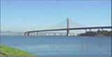
The eastern span replacement of the San Francisco – Oakland Bay Bridge has been under construction since 2002. Originally scheduled to open in 2007, it is now scheduled to open to traffic in 2013 at an estimated cost of $6.3 billion.
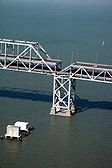
The original eastern span of the Bay Bridge, built in 1936, became the subject of concern after a section collapsed during the Loma Prieta earthquake
on October 17, 1989. The replacement span is engineered to withstand the largest earthquake expected over a 1500 year period, and it is expected to last at least 150 years with proper maintenance.
As of April 15, 2011, the Self-Anchored Suspension
(SAS) tower is structurally complete, having had its crowning main cable saddle placed on May 19th and needs only the final tower head, which will be lifted and temporarily fitted later this year. All 28 deck segments on the SAS span are in place and undergoing final welding. The installation of the eastern deviation saddles and strand anchor points will be followed by main cable spinning and suspender cable placement.
 During the 1989 Loma Prieta earthquake, which measured 6.9 on the moment magnitude scale
, a 50-foot (15 m) section of the upper deck of the eastern truss
portion of the bridge collapsed onto the deck below, indirectly causing one death at the point of collapse. The bridge was closed for a month and one day as construction crews reconstructed the fallen section. It reopened on November 18, 1989. The failure was at the transition between the easternmost through-truss and the westernmost double-deck causeway segment, a location where the inertial response character of the structure makes an abrupt change. Analysis of the event has shown that the bridge was close to a far more catastrophic failure in which either the through-truss or the causeway segment would have dropped from their common support structure.
Given the distance to the epicenter of the Loma Prieta (roughly 70 miles or 113 kilometers south of San Francisco), there was great surprise at the localized destruction around the Bay Area. Analysis points to the likelihood of reflected seismic waves from deep earth crust discontinuities. Failures were mostly located in areas of poor soil conditions due to building over filled-in creeks or on sand and rubble mixes from the 1906 earthquake—all of which were saturated with water and prone to liquefaction. (An exception was the Cypress Viaduct collapse, blamed on deficient engineering in certain details, combined with large-structure resonances that had not been considered during design.)
 It was clear that the eastern span needed to be made more earthquake resistant. It had been known for over thirty years that a major local earthquake on either of two nearby faults (the San Andreas
and the lesser-known but far more dangerous Hayward
) would destroy the major cantilever span
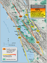
. Estimates made in 1999 placed the probability of a major earthquake in the area within the following 30 years at 70 percent, although recent studies announced in September 2004 by the United States Geological Survey
have cast doubt on the (statistical
) predictability of large earthquakes based upon the duration of preceding quiet periods; a more recent (2008) analysis asserts an increased probability of a major event on the Hayward Fault.
in a highly critical report and indirectly by the collapse of a retrofitted overpass in the 1994 Northridge earthquake
, that having been modified in response to the San Fernando event.
segment spans as seen in the illustration at right. The design criterion was that the new bridge should survive an 8.5 magnitude earthquake on any of several faults in the region, but particularly the nearby San Andreas and Hayward faults. The aesthetics of the proposal were not received well by either the public or their politicians, being characterized as a "freeway on stilts". The eastern span had long been considered ugly by most users, while the western span is widely considered a work of art, complementing the cityscape of San Francisco and comparable to the Golden Gate Bridge
.
Transportation Commission (MTC). A number of innovative proposals were examined until all but four proposals that were submitted by members of EDAP were selected as semi-finalists, and a winner was selected from this group. This posed a serious conflict of interest, as members of the Engineering and Design Advisory Panel (EDAP) who were selecting the bridge design reviewed proposals by their own firm and rejected all proposals that did not have a representative on the EDAP. The design chosen is intrinsically more expensive than the likely alternatives because the primary structure cannot be self supporting until it is structurally complete. This requires the building of two bridges, the first a falsework
to support the final span, and the falsework must in turn be removed upon completion.
) on opposite sides of the issue. Yerba Buena Island is within the city limits of San Francisco and the proposed (and current) northern alignment will cast a shadow over certain prime development sites on the island's eastern shore. Even the US Navy was involved and the delay may have caused up to a two year delay and many hundred millions of dollars in additional costs.
.
Grade alternatives included:
The last alternative being chosen as having a superior visual effect and improved driving experience. The grade of the new approach to the channel span is somewhat less than that of the present structure and less ship clearance is provided under the span owing mostly to the depth of the deck box structures.
Alignment alternatives included:
The last alternative was selected as it presents a superior view of San Francisco to the west compared to the others where views are obscured by Yerba Buena Island. Any more northerly track would encounter more difficult geotechnical circumstances. In this report and selection we see an emphasis on aesthetics
in an effort to build a bridge which is not merely functional, but beyond beautiful in that it is intended to enhance the experience of the users.
. In contrast, China has both low cost materials producers and major fabricators of bridge components, due to the current and extensive investment in infrastructure being made by her government. Other major components have been produced in Japan (not known as a low cost producer) owing to the availability of large steel casting, welding, and machining capabilities. Cable saddles come from England. A spokesman for the joint venture claimed the United States (in both private and public spheres) has neglected to make such investments for quite a long time and has as a consequence lost the ability to make suitably large steel components for civil structures such as this bridge.
("SAS") between the viaducts. When completed, this will become the largest bridge of this type, and will also have a number of unique features. The approach viaducts from the eastern shore are largely complete and located just north of and parallel to the existing truss viaduct.
and of concrete
. As both concrete and structural steel are now commodities within the worldwide market, the prices were much higher than expected because of the current building boom throughout China
. (China was then consuming 40 percent of worldwide cement production.) Another qualified potential bidder did not bid due to a number of construction uncertainties owing to the innovative design—another likely contribution to the very high bid. The entire project, which will require 100,000 tons of structural steel, is now expected to cost $6.2 billion (as of July 2005), up from a 1997 estimate of $1.1 billion (for a simple viaduct) and a March 2003 estimate of $2.6 billion that included a tower span.
announced that without sufficient funds authorized by the legislature that the bid must be allowed to expire. It was at the time unclear if this would require a redesign to obtain a less expensive span. It might have been possible to quickly redesign the span using a more conventional cable stayed design, for which the construction methods and costs are well understood but the cost of the resultant delay was likely to far exceed any potential savings.
On December 10, 2004, the governor's office announced that the signature span concept had been scrapped, with the completion of the bridge to be by the construction of the simple viaduct originally proposed. The design, having gone full circle, remained expensive due to the continued high cost of materials. Many argued that there would be little difference in final cost with this lesser proposal since that concept required obtaining new permits, perhaps adding an additional two or three years; furthermore, a viaduct may not even be able to obtain Coast Guard approval since the maximum width of the ship channel would be reduced by almost half. Local reaction to this announcement was intense, with most suggesting that the bridge be built to appear as proposed — either in the steel material as bid or using a reinforced concrete tower of similar appearance but of lower cost
) problem. Northern Californians pointed out that when the southern portions of the state experienced disasters, the state supported rebuilding, especially as seen in earthquake rebuilding of freeways and the subsequent seismic retrofit of state freeway structures and bridges. Since the objective of the replacement of the eastern span is to prevent the necessity of complete rebuilding after a large earthquake, Bay Area residents felt justified in their call for state support.
A compromise was announced on June 24, 2005 by Governor Schwarzenegger. The governor said that he and State Senate President Pro Tempore Don Perata
reached agreement to resurrect plans for the signature span. Cost estimates of the contract deferral expenses and inflation range attributable to the delay have ranged up to $400 million. Direct costs due to cessation of work (which included some dismantling of temporary structures and its recent restart) were determined in late 2005 to be $85 million.
After being approved by the Legislature, the compromise legislation was signed by the governor on July 18, 2005. The compromise calls for the state to contribute $630 million to help cover the $3.6 billion in cost overruns, and bridge tolls will be raised to $4 starting in 2007. At the time of the signing, the skyway portion of the bridge was 75 percent complete and the state was beginning to prepare to put the suspension span out for new bids. The entire project is scheduled to be completed in 2013 at an estimated cost of $6.3 billion, not counting the demolition of the old span.
In January 2006, costs for the main structure steelwork were determined to be $400 million in excess of these expectations. New bids for the main span were opened on March 22, 2006, with two submissions at 1.43 and 1.6 billion USD. Owing to reserves built up with a $3.00 toll during the delay it was initially suggested by authorities that additional tolls exceeding $4.00 would not be required, but due to added costs in other portions due to the delay and the cost of restarting the main span foundation work, an eventual toll of $5.00 is now expected. (The toll is only collected in the westbound direction.) The low bid by a joint venture of American Bridge
and Fluor Corp. was accepted on April 19, 2006.
announced an investigation into charges by fifteen former welders and inspectors on the new eastern span that welders were rushed to an extent affecting their performance on up to one third of the welds and that workers were ordered to cover up defective welds by re-welding in a superficial manner. Many of these welds were now embedded in concrete, some deeply underwater.
A Caltrans spokesperson quickly responded with a public assertion that it was not possible that defective welds could be hidden from Caltrans inspectors. This assertion was subsequently tested by radiological, ultrasonic and microscopic inspection of some of the welds that were accessible yet alleged to be deficient. On April 21, 2005, news reports indicated that the Federal Highway Administration
hired private inspectors to remove 300 pound (136 kg) sections for detailed laboratory analysis.
On May 4, 2005, local radio reported that the Federal Highway Administration said the tests by three independent contractors showed that welds pulled from three 500 pound steel chunks of the bridge "either met or exceeded required specifications."
Since some of the material removed for inspection was specifically identified by the welders' complaints as worthy of inspection, this finding was received as very good news.
component of the existing main eastern span.
Found in one of eight bars sharing the same load, the crack was not present two years earlier. Discovery of this crack by itself would likely have caused an immediate bridge closure, so the timing was fortunate. Additional components to distribute the load around the crack were promptly designed and fabricated overnight, arriving by charter air from Arizona. The repair was completed ahead of schedule and the bridge was reopened a day before the original estimate, resulting in only minimal impact to typical area traffic.
On October 27, 2009, during the evening commute, parts of the September emergency repair, a crossbar and two tension rods, collapsed onto the upper deck roadway. One car and a delivery truck were struck by or collided with the 2.25 tons of debris. The bridge was closed to traffic in both directions for six days, reopening on November 2, 2009.
The failure of the repair was caused by two design defects: first, the tie rods closely fit the holes in the cross pieces over the saddles and second, wind caused vibrations in the rods, which in turn caused wear and bending at the through holes, eventually causing a rod fracture. The catastrophic dropping of the cross piece was caused by a lack of structural attachment to the saddle, being retained only by tack welds
, friction
and the tension of the tie rods. The rework of the design included six significant modifications:
Proper fitting had proved difficult, requiring the disassembly of the new components to gain access for rework.
A more permanent repair was made in December 2009. The bridge remained open to traffic while crews cut away the cracked end of the eyebar and spliced a new end to the undamaged part of the eyebar with a pair of gusset plate
s. The repaired eyebar was placed under tension and the temporary block and tie rod assemblies were removed.
 On December 14, 2004, the San Francisco Board of Supervisors
, in honor of Joshua A. Norton
, passed a resolution 8–2 (1 absent), file number 041618, "urging the California Department of Transportation and members of the California Assembly and Senate to name the new additions to the San Francisco Bay Bridge in honor of Emperor Norton I, Emperor of the United States and Protector of Mexico.", According to the Oakland City Counsel, the naming of the new San Francisco Oakland Bridge was rejected and will not be named after Joshua A. Norton.
unveiled a new logo featuring the yet to be completed self anchored suspension span. The new logo was debuted in the 2010–2011 season.
Viaduct images
 By 2007, 75 percent of the skyway portion was completed, which will connect the SAS portion of the bridge with the Oakland shore. As this section crosses the shallower portion of the bay the foundations could be constructed within sheet-pile cofferdams. By mid-2009 the final connection of the viaduct portion with ground level at the eastern end was undergoing completion and the pedestrian walkway was being attached to the completed sections. A drive-by on the completed skyway can be seen here.
s) at angles, forming a "battered" (splayed) footing. Where long pilings were needed segments would be welded together as completed segments were driven deep. When all pilings were in place a reenforced concrete pad was poured at the bottom of the cofferdam to form a footing for the column, subsequently cast in place around rebar using reusable metal formwork.
, were barged to the location and lifted into place with a specialized cantilever lift. (Cantilever lifts, counterweights and other equipment and materials were lifted by a barge crane or by a jack-up crane located between each column pair.) Once in the proper location the pair could then be joined with through tenons, forming a balanced cantilever over the column. Eventually the gap in spans between columns could be closed, forming a tenon-reenforced beam.
The next stage in touchdown development will be to construct a temporary structure to carry the westbound upper deck in a similar southern loop, now possible since the eastbound traffic is now more southerly. When that work is complete a portion of the double deck truss structure will be removed at that location to allow the construction of the new span's eastbound touchdown.
. Unlike other examples it is particularly unique in being both single tower and asymmetrical
, a design tailored to the site. For ship channel clearance the bridge would require at least one long span, while ready access to bedrock was found only close to Yerba Buena Island. A two tower cable-stayed
design would require very deep tower footings, and a conventional two tower suspension bridge
would additionally require a massive anchor to be built in deep bay mud. The curved nature of the approach places additional constraints on the design. Construction progress of the main span is shown here (Bay Bridge Info).
While earlier bridges of this type use chain eyebar
s, the long span needed here uses spun-in-place wire cable as do other modern suspension bridges, but uniquely, this is a single loop of cable rather than the usual pair of cables.
Being asymmetrical, the shorter western span must be pulled down against the forces imposed by the longer eastern span. In order to avoid uplift in the supporting columns the span is terminated with a massive concrete end weight, currently supported solely by the columns. This end weight also carries the turning saddles for the main cables. As seen in the northwest corner image above, there is an upward component to the tension force provided by the main cable, and it is this component that removes most of the weight of the end cap from its columns. (The greater, horizontal, component is countered by the compressive forces exerted by the box deck structure as is characteristic of this type of bridge.)
Furthermore, the segments of each of the two deck spans will be retained in compression during a severe earthquake by post-tensioned tenons joining the extreme end caps, these carried internally in cable trays. These tenons are required since the eastern end cap is both much lighter than the western cap and the soil conditions are radically different at each end, the western end being founded in bedrock shale while the eastern end, while driven to bedrock, is mostly contained with mud deposits, deposits which respond much more actively to seismic shocks than the shale. The intent is that the combination of the tensioned tenons and the compressive roadbed box structure will keep the two end caps in the same relative position.
The bridge segments at each end are not simple repetitions of the central span segments:
S-curve images
On September 3, 2007 the first section associated with the construction of the new East Span, the 300 feet (91.4 m) temporary span connecting the main cantilever section to the Yerba Buena Island Tunnel, was put into service. Construction of the new connector span started in early 2007 alongside the existing span. Caltrans closed the Bay Bridge during the Labor Day weekend so crews could remove the old span. Once the old section was removed the new span was rolled into place using a computer-guided system of hydraulic jacks and rollers. The new section was secured into place and the bridge re-opened eleven hours ahead of schedule for the morning commute on the Tuesday (September 4, 2007) following the weekend. On September 2009 during a single holiday closure, new temporary steelwork to route traffic around the location of the final approaches to the new bridge is in place and its connections to the tunnel exit and the existing bridge were completed, much as was done in September 2007. This bypass enables the construction of the permanent transition structure between the double-deck tunnel exit and the new side-by-side bridge structure. Upon completion of the bridge another extended closure will allow the removal of the temporary structure and the completion of the road link.
All of the section of the old span over Yerba Buena Island (around which the S-curve routes traffic) has been dismantled, and supports for the new span are currently being built in that location.
The S-curve site has become well-known for accidents, from fender-benders to a fatal plunge. Mostly wrecks occur during non-commute time, when traffic flows faster, at or above the general bridge limit of 50 mph. Additional signage and visual and physical indicators indicating the 40 mph S-curve speed limit were installed following the major accident. The upper deck speed advisory at the curve has been posted as 35 mph and an improved system of "rumble strips" has been installed.
The falsework to perform this task is a pair of substantial truss bridge
s, prefabricated in segments, with columns and span segments lifted into place by barge cranes. The trusses are supported on foundations consisting of or built atop deeply driven piles. Upon completion of the bridge the entire falsework structure and all exposed underwater supports will be removed to make a safe channel for deep draft ships transiting to and from the Port of Oakland
.
By late August 2009 the temporary column work was complete, truss spans were in place and prefabricated sections were being placed upon it. A giant barge crane, the Left Coast Lifter
, was used to emplace the 28 main deck box structures. Major segment placement on the SAS section of the bridge was completed in early October 2011 and final welding is in progress. On October 19, 2011 the small gap between the SAS deck and the curved skyway extension was finally closed for the east-bound side with the west-bound gap being closed the following week. Today the deck placement of the SAS span is finally complete, making 11/2 miles of continuous roadway from the Oakland Touchdown, all across the skyway, onto the SAS and all the way to Yerba Buena Island non-stop without any gaps.
The tower consists of four columns. Each roughly pentagonal column consists of four tapering and/or straight sections joined end-to-end by external plates and internal stringer finger joints secured with fasteners. (Images of the lifting and joining methods may be seen here.) The columns are also joined horizontally by sacrificial box structures. These box joins are intended to absorb earthquake-induced motion by elastic and plastic shear deformation as the tower sways. Under a severe earthquake this deformation absorbs energy that could otherwise lead to destructive tower motion, thus protecting the primary structure of the span. It is expected that this design will allow the immediate use of the bridge for emergency vehicles, with the joins being replaced as needed to restore the bridge to its original condition. Uniquely, the tower has no direct connection to the roadbeds, with enough space to allow swaying under severe earthquakes without collision.
The tower also has an unusual appearance at certain daylight lighting angles. Near sunrise and sunset multiple illuminations from the bright white paint can cause a subtle glow to appear from the tower's interior surfaces, depending on the season. Other effects will appear more consistently at night from electric lighting.
Tower erection continued when the second set of columns finally arrived on the week of October 24, almost three months after the first set were placed. The second set of columns were erected by a gantry atop the scaffold and were placed over the first four columns that were placed earlier in the year. After the columns were set into place, they were bolted together with the first set of columns. After this second phase was complete, the tower was now about 51 percent completed and stood at a height of 272 feet. The third set of tower columns didn't arrive until the week of December 15 but it was still early enough to have the third phase completed before the holidays. The third set, now with a larger crane, were lifted and placed over the second set of columns. The tower now stood at an impressive height of 374 feet and was 71 percent complete. The erection process did not continue until the following year when the final set of tower columns finally arrived by Valentine's Day 2011. These four columns, each being 105.6 feet tall, were lifted on the week of February 28 and placed over the third set of columns. The tower now stood at a height of 480 feet and was now 91 percent complete.
The fifth and final tower phase was to lift a grillage that weighs about 500 tons, lift the main 450-ton cable saddle, and finally lift the final tower head which will complete the entire SAS tower. All of these final pieces arrived at the site the same day the fourth set of tower columns arrived. On April 15, the first part of the fifth and final phase was initiated. The 500-ton grillage was lifted up 500 feet in the air and was placed over the fourth set of columns. The tower then stood at a height of 495 feet and is now 94 percent complete. It took about one day to lift and place the grillage on top of the tower.
This cable saddle will guide and support the mile-long main cable over the tower, but the cable will not be installed until the end of the year, as soon as all of the deck placement of the SAS span is complete. However, sometime in July the tower head will be lifted and placed over the saddle in a test fitting to see if it fits perfectly in place, but the tower head will then be removed to allow the laying of the cable. Once the cables are placed and are anchored throughout the whole SAS span, the tower head will then be permanently emplaced. With the emplacement of permanent aircraft warning beacons the entire SAS tower will be completed at a final height of 525 feet (160 m).
The tower saddle includes eyebar
s for the attachment of temporary cables that support four walkways, each a simple suspension bridge
(called a catwalk) that allows access to the cable spinning mechanism and the main cable. In several ways similar to a ski lift
, additional superior cables will carry one or more of these travelers, wheeled devices that shuttle from one end of the span to the other, pulled by drafting cables manipulated by several winches.
Cable images
The main span use a single cable, spun a few wires at a time as follows:
As with a conventional cable suspension span a group of wires from a set of anchor eyes is bundled together, with all of the bundles finally compressed into a circular shape and protected with a circular wrap of wire. Saddles for suspender cables will be added and suspender cables placed and tensioned.
In mid June, 2011 preparations for the spinning of the main cable began by installing the temporary catwalks on the SAS span. Both western catwalks were installed and by mid August, all four catwalks were installed in place and an approximation of the completed outline of the bridge may be seen. All four catwalks, the traveler, its suspension cable and the drafting cables and the winches must be in place before cable spinning can begin. These catwalks are required for worker's access to the cable strands for bundling and arrangement as the individual wires are placed.
Work in September included the installation of turning tracks for the travelers at the western deviation saddles. These tracks will allow continuous motion of the traveler across the western end of the main span. By mid October the traveler cables were installed. A temporary group of tower stay cables to the west, intended to resist the overturning forces imposed by the bare main cable, have also been installed.
Before the cables can be spun, the eastern end must be completed with the installation of two deviation saddles on each side and all termination eyes must be in place on the eastern end of the main span, work not completed as of mid October.
On this bridge the deck sections are already in a fixed relative position (being bolted together and resting upon the falsework) and all suspender cables must be brought to specific tensions individually before the final main cable tensioning.
system at the more sensitive column locations. In addition, the western landing of the YBITS is a zero moment hinge
, and so there are no bending stresses at that point.
(February 28 - June 7, 2011)
The first step is to construct foundations of the large columns which will support the elevated roadway of the YBITS. Above-grade column reenforcing is constructed and enclosed by formwork
and concrete is emplaced. After curing the formwork is then removed. The next step is to build the actual roadway itself. The two principle techniques that may be employed are the use of precast, post-tensioned segments (as were used to construct the eastern "skyway" approach), or to cast the spans in place, using extensive reenforcing, (the method used for the YBITS) often with post-tensioned cable tenons. In this case the roadways consist of hollow box structures, cast in place in sections using formwork, owing both to the complex shapes involved and the necessity of maintaining traffic flow during construction.
The following sequence is applied to each span between columns:
MTC – News. This shows the placement of the bridge deck sections and the use of a jack-up crane to erect the tower scaffold, with the placing of sections of the tower by a gantry
atop the scaffold. This simulation takes the construction up to its current state as of late May, 2011 and does not include the cable spinning. For current site camera views, see this MTC site. These cameras include views of the SAS and YBITS, both panoramic and with specific views.
documentary on the building of the original SFOBB shows the cable spinning method that will be used on the new span starting at 7 minutes in with the anchorage eybars and continuing with building the catwalk, spinning the cables, and placing the suspenders. As with the replacement span, American Bridge was a major contractor on that job, too.
A fly-by video was also shot on the same day from above. This video shows the current traffic and the construction progess of the SAS from an extraordinary aerial view.
The original eastern span of the Bay Bridge, built in 1936, became the subject of concern after a section collapsed during the Loma Prieta earthquake
Loma Prieta earthquake
The Loma Prieta earthquake, also known as the Quake of '89 and the World Series Earthquake, was a major earthquake that struck the San Francisco Bay Area of California on October 17, 1989, at 5:04 p.m. local time...
on October 17, 1989. The replacement span is engineered to withstand the largest earthquake expected over a 1500 year period, and it is expected to last at least 150 years with proper maintenance.
As of April 15, 2011, the Self-Anchored Suspension
Self-anchored suspension bridge
A self-anchored suspension bridge is a suspension bridge in which the main cables attach to the ends of the deck, rather than to the ground via large anchorages...
(SAS) tower is structurally complete, having had its crowning main cable saddle placed on May 19th and needs only the final tower head, which will be lifted and temporarily fitted later this year. All 28 deck segments on the SAS span are in place and undergoing final welding. The installation of the eastern deviation saddles and strand anchor points will be followed by main cable spinning and suspender cable placement.
Seismic hazard
It has been widely known that the eastern span was likely to collapse in a major earthquake. Other than amongst users of the bridge there was little interest in addressing the problem, either locally or within the California Department of Transportation ("CalTrans"), with most CalTrans seismic retrofit work before the 1989 Loma Prieta earthquake being done in response to the 1971 San Fernando earthquake, which exposed the vulnerability of freeway overpass structures.Earthquake damage
Moment magnitude scale
The moment magnitude scale is used by seismologists to measure the size of earthquakes in terms of the energy released. The magnitude is based on the seismic moment of the earthquake, which is equal to the rigidity of the Earth multiplied by the average amount of slip on the fault and the size of...
, a 50-foot (15 m) section of the upper deck of the eastern truss
Truss bridge
A truss bridge is a bridge composed of connected elements which may be stressed from tension, compression, or sometimes both in response to dynamic loads. Truss bridges are one of the oldest types of modern bridges...
portion of the bridge collapsed onto the deck below, indirectly causing one death at the point of collapse. The bridge was closed for a month and one day as construction crews reconstructed the fallen section. It reopened on November 18, 1989. The failure was at the transition between the easternmost through-truss and the westernmost double-deck causeway segment, a location where the inertial response character of the structure makes an abrupt change. Analysis of the event has shown that the bridge was close to a far more catastrophic failure in which either the through-truss or the causeway segment would have dropped from their common support structure.
Given the distance to the epicenter of the Loma Prieta (roughly 70 miles or 113 kilometers south of San Francisco), there was great surprise at the localized destruction around the Bay Area. Analysis points to the likelihood of reflected seismic waves from deep earth crust discontinuities. Failures were mostly located in areas of poor soil conditions due to building over filled-in creeks or on sand and rubble mixes from the 1906 earthquake—all of which were saturated with water and prone to liquefaction. (An exception was the Cypress Viaduct collapse, blamed on deficient engineering in certain details, combined with large-structure resonances that had not been considered during design.)
San Andreas Fault
The San Andreas Fault is a continental strike-slip fault that runs a length of roughly through California in the United States. The fault's motion is right-lateral strike-slip...
and the lesser-known but far more dangerous Hayward
Hayward Fault Zone
The Hayward Fault Zone is a geologic fault zone capable of generating significantly destructive earthquakes. This strike-slip fault is about long, situated mainly along the western base of the hills on the east side of San Francisco Bay...
) would destroy the major cantilever span
Cantilever bridge
A cantilever bridge is a bridge built using cantilevers, structures that project horizontally into space, supported on only one end. For small footbridges, the cantilevers may be simple beams; however, large cantilever bridges designed to handle road or rail traffic use trusses built from...
. Estimates made in 1999 placed the probability of a major earthquake in the area within the following 30 years at 70 percent, although recent studies announced in September 2004 by the United States Geological Survey
United States Geological Survey
The United States Geological Survey is a scientific agency of the United States government. The scientists of the USGS study the landscape of the United States, its natural resources, and the natural hazards that threaten it. The organization has four major science disciplines, concerning biology,...
have cast doubt on the (statistical
Statistics
Statistics is the study of the collection, organization, analysis, and interpretation of data. It deals with all aspects of this, including the planning of data collection in terms of the design of surveys and experiments....
) predictability of large earthquakes based upon the duration of preceding quiet periods; a more recent (2008) analysis asserts an increased probability of a major event on the Hayward Fault.
To be retrofited
The initial proposal for the eastern span involved the construction of substantial concrete columns to replace or supplement the existing supports. There would also be modifications to the lattice beams as is now complete for the western span. The original cost estimate for this refit was $200 million. The overall appearance would be little changed. Owing to the retention of the original structure the bridge's ongoing maintenance costs would continue to be high compared to a replacement span. The robustness of a retrofit was called into question directly by the Army Corps of EngineersUnited States Army Corps of Engineers
The United States Army Corps of Engineers is a federal agency and a major Army command made up of some 38,000 civilian and military personnel, making it the world's largest public engineering, design and construction management agency...
in a highly critical report and indirectly by the collapse of a retrofitted overpass in the 1994 Northridge earthquake
Northridge earthquake
The Northridge earthquake was a massive earthquake that occurred on January 17, 1994, at 04:31 Pacific Standard Time in Reseda, a neighborhood in the city of Los Angeles, California, lasting for about 10–20 seconds...
, that having been modified in response to the San Fernando event.
To be replaced
Engineering and economic analysis in 1996 suggested that a simple replacement bridge would cost a few hundred million dollars more than a retrofit of the existing eastern span and that a replacement would have a far longer expected useful life (perhaps 75 to 100 years rather than 30) and would require far less maintenance. Rather than retrofit the existing bridge the authorities decided to replace the entire eastern span. The design proposed was a simple elevated viaduct consisting of reinforced concrete columns and precast concretePrecast concrete
By producing precast concrete in a controlled environment , the precast concrete is afforded the opportunity to properly cure and be closely monitored by plant employees. Utilizing a Precast Concrete system offers many potential advantages over site casting of concrete...
segment spans as seen in the illustration at right. The design criterion was that the new bridge should survive an 8.5 magnitude earthquake on any of several faults in the region, but particularly the nearby San Andreas and Hayward faults. The aesthetics of the proposal were not received well by either the public or their politicians, being characterized as a "freeway on stilts". The eastern span had long been considered ugly by most users, while the western span is widely considered a work of art, complementing the cityscape of San Francisco and comparable to the Golden Gate Bridge
Golden Gate Bridge
The Golden Gate Bridge is a suspension bridge spanning the Golden Gate, the opening of the San Francisco Bay into the Pacific Ocean. As part of both U.S. Route 101 and California State Route 1, the structure links the city of San Francisco, on the northern tip of the San Francisco Peninsula, to...
.
Signature span proposals and selection
A design contest was held for a signature span (a span with distinctive and dramatic appearance, unique to the site) by the Engineering and Design Advisory Panel (EDAP) of the MetropolitanTransportation Commission (MTC). A number of innovative proposals were examined until all but four proposals that were submitted by members of EDAP were selected as semi-finalists, and a winner was selected from this group. This posed a serious conflict of interest, as members of the Engineering and Design Advisory Panel (EDAP) who were selecting the bridge design reviewed proposals by their own firm and rejected all proposals that did not have a representative on the EDAP. The design chosen is intrinsically more expensive than the likely alternatives because the primary structure cannot be self supporting until it is structurally complete. This requires the building of two bridges, the first a falsework
Falsework
Falsework consists of temporary structures used in construction to support spanning or arched structures in order to hold the component in place until its construction is sufficiently advanced to support itself...
to support the final span, and the falsework must in turn be removed upon completion.
Alignment controversy
In 1997 there was much political bickering over whether the bridge should be built to the north or to the south of the existing bridge, with the "Mayors Brown" (San Francisco's Willie Brown and Oakland's Jerry BrownJerry Brown
Edmund Gerald "Jerry" Brown, Jr. is an American politician. Brown served as the 34th Governor of California , and is currently serving as the 39th California Governor...
) on opposite sides of the issue. Yerba Buena Island is within the city limits of San Francisco and the proposed (and current) northern alignment will cast a shadow over certain prime development sites on the island's eastern shore. Even the US Navy was involved and the delay may have caused up to a two year delay and many hundred millions of dollars in additional costs.
Signature span grade and location alternatives
Various options were determined to be worthy of consideration and were carefully examined jointly by state and federal authorities, with input from the United States Coast GuardUnited States Coast Guard
The United States Coast Guard is a branch of the United States Armed Forces and one of the seven U.S. uniformed services. The Coast Guard is a maritime, military, multi-mission service unique among the military branches for having a maritime law enforcement mission and a federal regulatory agency...
.
Grade alternatives included:
- Extending the sea level approach grade westward, with a steep approach to the span.
- Using a relatively constant grade, including on a portion of the span.
- Using a relatively constant grade to near the span, with the span level.
The last alternative being chosen as having a superior visual effect and improved driving experience. The grade of the new approach to the channel span is somewhat less than that of the present structure and less ship clearance is provided under the span owing mostly to the depth of the deck box structures.
Alignment alternatives included:
- S4: a southern alignment, slightly curved, but a shorter route than the northern alternatives.
- N2: a two-bend northern alignment close to the existing bridge.
- N6: a single bend alignment, with the main span tending northward to the curve to the eastern approach viaducts, those being parallel to the existing double-deck truss causeway approach.
The last alternative was selected as it presents a superior view of San Francisco to the west compared to the others where views are obscured by Yerba Buena Island. Any more northerly track would encounter more difficult geotechnical circumstances. In this report and selection we see an emphasis on aesthetics
Aesthetics
Aesthetics is a branch of philosophy dealing with the nature of beauty, art, and taste, and with the creation and appreciation of beauty. It is more scientifically defined as the study of sensory or sensori-emotional values, sometimes called judgments of sentiment and taste...
in an effort to build a bridge which is not merely functional, but beyond beautiful in that it is intended to enhance the experience of the users.
Offshore fabrication
Even though controversial, authorities decided to allow bids to include major components and materials not made in the United States. This was partially due to the cost of materials, but more substantially, required by the lack of suitable fabrication facilities within this country, or even within the western hemisphere. Since such facilities would have to be built anew and the prospects of additional work would be uncertain, the cost of fabrication would be much higher. As acceptance of Federal Highway funds generally come with "Made in America" restrictions, the bridge is being built without such funds, for which it would otherwise qualify owing to its carriage of Interstate 80Interstate 80
Interstate 80 is the second-longest Interstate Highway in the United States, following Interstate 90. It is a transcontinental artery running from downtown San Francisco, California to Teaneck, New Jersey in the New York City Metropolitan Area...
. In contrast, China has both low cost materials producers and major fabricators of bridge components, due to the current and extensive investment in infrastructure being made by her government. Other major components have been produced in Japan (not known as a low cost producer) owing to the availability of large steel casting, welding, and machining capabilities. Cable saddles come from England. A spokesman for the joint venture claimed the United States (in both private and public spheres) has neglected to make such investments for quite a long time and has as a consequence lost the ability to make suitably large steel components for civil structures such as this bridge.
Construction begins
After more than a decade of study, construction began on a replacement for the cantilever portion of the bridge on January 29, 2002, with completion originally slated for 2007. The new eastern "signature" span was to feature a pair of side-by-side, five-lane concrete viaducts linking to a single-towered, self-anchored suspension spanSelf-anchored suspension bridge
A self-anchored suspension bridge is a suspension bridge in which the main cables attach to the ends of the deck, rather than to the ground via large anchorages...
("SAS") between the viaducts. When completed, this will become the largest bridge of this type, and will also have a number of unique features. The approach viaducts from the eastern shore are largely complete and located just north of and parallel to the existing truss viaduct.
A price shock
The authorities were shocked when they opened the bids on the proposed tower portion, as there was only a single bid and it was considerably more expensive (US$1.4 billion) than their estimate ($780 million), partially because of a recent and unexpected rise both in the cost of steelSteel
Steel is an alloy that consists mostly of iron and has a carbon content between 0.2% and 2.1% by weight, depending on the grade. Carbon is the most common alloying material for iron, but various other alloying elements are used, such as manganese, chromium, vanadium, and tungsten...
and of concrete
Concrete
Concrete is a composite construction material, composed of cement and other cementitious materials such as fly ash and slag cement, aggregate , water and chemical admixtures.The word concrete comes from the Latin word...
. As both concrete and structural steel are now commodities within the worldwide market, the prices were much higher than expected because of the current building boom throughout China
China
Chinese civilization may refer to:* China for more general discussion of the country.* Chinese culture* Greater China, the transnational community of ethnic Chinese.* History of China* Sinosphere, the area historically affected by Chinese culture...
. (China was then consuming 40 percent of worldwide cement production.) Another qualified potential bidder did not bid due to a number of construction uncertainties owing to the innovative design—another likely contribution to the very high bid. The entire project, which will require 100,000 tons of structural steel, is now expected to cost $6.2 billion (as of July 2005), up from a 1997 estimate of $1.1 billion (for a simple viaduct) and a March 2003 estimate of $2.6 billion that included a tower span.
Governor kills signature span
On September 30, 2004, the office of Governor Arnold SchwarzeneggerArnold Schwarzenegger
Arnold Alois Schwarzenegger is an Austrian-American former professional bodybuilder, actor, businessman, investor, and politician. Schwarzenegger served as the 38th Governor of California from 2003 until 2011....
announced that without sufficient funds authorized by the legislature that the bid must be allowed to expire. It was at the time unclear if this would require a redesign to obtain a less expensive span. It might have been possible to quickly redesign the span using a more conventional cable stayed design, for which the construction methods and costs are well understood but the cost of the resultant delay was likely to far exceed any potential savings.
On December 10, 2004, the governor's office announced that the signature span concept had been scrapped, with the completion of the bridge to be by the construction of the simple viaduct originally proposed. The design, having gone full circle, remained expensive due to the continued high cost of materials. Many argued that there would be little difference in final cost with this lesser proposal since that concept required obtaining new permits, perhaps adding an additional two or three years; furthermore, a viaduct may not even be able to obtain Coast Guard approval since the maximum width of the ship channel would be reduced by almost half. Local reaction to this announcement was intense, with most suggesting that the bridge be built to appear as proposed — either in the steel material as bid or using a reinforced concrete tower of similar appearance but of lower cost
Governor's economic analysis questioned
The standpoint of pro-"signature bridge" activists and regional politicians was reinforced by a legislative analyst's report in late January 2005. The report indicated, due to additional time delays and all new permitting requirements, that the governor's skyway proposal could likely cost additional funding and take longer to complete than the proposed signature span. This view was reinforced by a further report in March 2005 indicating that the delay imposed by the governor had already added at least $100 million to the expected cost, subsequently refined to $83 million in a December 2005 report. Some of the temporary foundation structures for the main span had been removed and subsequently had to be replaced, in addition to inflation of costs over time.To be built as designed
The design controversy continued for over six months. In essence, the governor believed that the entire state should not share in the costs of building the bridge, as he considered it to be a local (Bay AreaSan Francisco Bay Area
The San Francisco Bay Area, commonly known as the Bay Area, is a populated region that surrounds the San Francisco and San Pablo estuaries in Northern California. The region encompasses metropolitan areas of San Francisco, Oakland, and San Jose, along with smaller urban and rural areas...
) problem. Northern Californians pointed out that when the southern portions of the state experienced disasters, the state supported rebuilding, especially as seen in earthquake rebuilding of freeways and the subsequent seismic retrofit of state freeway structures and bridges. Since the objective of the replacement of the eastern span is to prevent the necessity of complete rebuilding after a large earthquake, Bay Area residents felt justified in their call for state support.
A compromise was announced on June 24, 2005 by Governor Schwarzenegger. The governor said that he and State Senate President Pro Tempore Don Perata
Don Perata
Don Richard Perata is a California Democratic politician, who was President pro tempore of the California State Senate from 2004 to 2008. He came in second place in the November 2010 ballot for Mayor of Oakland...
reached agreement to resurrect plans for the signature span. Cost estimates of the contract deferral expenses and inflation range attributable to the delay have ranged up to $400 million. Direct costs due to cessation of work (which included some dismantling of temporary structures and its recent restart) were determined in late 2005 to be $85 million.
After being approved by the Legislature, the compromise legislation was signed by the governor on July 18, 2005. The compromise calls for the state to contribute $630 million to help cover the $3.6 billion in cost overruns, and bridge tolls will be raised to $4 starting in 2007. At the time of the signing, the skyway portion of the bridge was 75 percent complete and the state was beginning to prepare to put the suspension span out for new bids. The entire project is scheduled to be completed in 2013 at an estimated cost of $6.3 billion, not counting the demolition of the old span.
In January 2006, costs for the main structure steelwork were determined to be $400 million in excess of these expectations. New bids for the main span were opened on March 22, 2006, with two submissions at 1.43 and 1.6 billion USD. Owing to reserves built up with a $3.00 toll during the delay it was initially suggested by authorities that additional tolls exceeding $4.00 would not be required, but due to added costs in other portions due to the delay and the cost of restarting the main span foundation work, an eventual toll of $5.00 is now expected. (The toll is only collected in the westbound direction.) The low bid by a joint venture of American Bridge
American Bridge Company
The American Bridge Company is a privately held civil engineering firm specializing in the construction and renovation of bridges and other large civil engineering projects, founded in 1900, and headquartered in Coraopolis, Pennsylvania, a suburb of Pittsburgh.-Products and industry positioning:The...
and Fluor Corp. was accepted on April 19, 2006.
Weld controversy
On April 6, 2005, the FBIFederal Bureau of Investigation
The Federal Bureau of Investigation is an agency of the United States Department of Justice that serves as both a federal criminal investigative body and an internal intelligence agency . The FBI has investigative jurisdiction over violations of more than 200 categories of federal crime...
announced an investigation into charges by fifteen former welders and inspectors on the new eastern span that welders were rushed to an extent affecting their performance on up to one third of the welds and that workers were ordered to cover up defective welds by re-welding in a superficial manner. Many of these welds were now embedded in concrete, some deeply underwater.
A Caltrans spokesperson quickly responded with a public assertion that it was not possible that defective welds could be hidden from Caltrans inspectors. This assertion was subsequently tested by radiological, ultrasonic and microscopic inspection of some of the welds that were accessible yet alleged to be deficient. On April 21, 2005, news reports indicated that the Federal Highway Administration
Federal Highway Administration
The Federal Highway Administration is a division of the United States Department of Transportation that specializes in highway transportation. The agency's major activities are grouped into two "programs," the Federal-aid Highway Program and the Federal Lands Highway Program...
hired private inspectors to remove 300 pound (136 kg) sections for detailed laboratory analysis.
On May 4, 2005, local radio reported that the Federal Highway Administration said the tests by three independent contractors showed that welds pulled from three 500 pound steel chunks of the bridge "either met or exceeded required specifications."
- From a consultant (Mays) "The overall weld quality is excellent and greatly surpasses typical field welding quality that we have seen on similar structures."
- From a consultant (Teal) "...I found that most welds, although incomplete at many locations, generally conformed to the quality requirements of ANSI/AASHTO/AWS D1.5–96, and therefore conformed to the quality requirements of the Contract documents."
- From a consultant (Fisher) "The weld quality provided in the steel footing boxes for the connection of the steel piles to the pile sleeves was found to be very good. The QA/QC provided by this project equals or exceeds that required by most states."
Since some of the material removed for inspection was specifically identified by the welders' complaints as worthy of inspection, this finding was received as very good news.
Eyebar crack, repair, subsequent failure and bridge closure
An inspection during a construction-related closure in September 2009 revealed a crack in a critical eyebarEyebar
In structural engineering and construction, an eyebar is a straight bar, usually of metal, with a hole at each end for fixing to other components...
component of the existing main eastern span.
Found in one of eight bars sharing the same load, the crack was not present two years earlier. Discovery of this crack by itself would likely have caused an immediate bridge closure, so the timing was fortunate. Additional components to distribute the load around the crack were promptly designed and fabricated overnight, arriving by charter air from Arizona. The repair was completed ahead of schedule and the bridge was reopened a day before the original estimate, resulting in only minimal impact to typical area traffic.
On October 27, 2009, during the evening commute, parts of the September emergency repair, a crossbar and two tension rods, collapsed onto the upper deck roadway. One car and a delivery truck were struck by or collided with the 2.25 tons of debris. The bridge was closed to traffic in both directions for six days, reopening on November 2, 2009.
The failure of the repair was caused by two design defects: first, the tie rods closely fit the holes in the cross pieces over the saddles and second, wind caused vibrations in the rods, which in turn caused wear and bending at the through holes, eventually causing a rod fracture. The catastrophic dropping of the cross piece was caused by a lack of structural attachment to the saddle, being retained only by tack welds
Welding
Welding is a fabrication or sculptural process that joins materials, usually metals or thermoplastics, by causing coalescence. This is often done by melting the workpieces and adding a filler material to form a pool of molten material that cools to become a strong joint, with pressure sometimes...
, friction
Friction
Friction is the force resisting the relative motion of solid surfaces, fluid layers, and/or material elements sliding against each other. There are several types of friction:...
and the tension of the tie rods. The rework of the design included six significant modifications:
- Structural welding of the cross pieces to the saddles to prevent catastrophic disassembly
- Enlargement of the through holes to eliminate contact with the tie rods
- Addition of a spherical seat and matching tie rod tensioning nut to reduce concentrated bending loads at the nut
- Addition of tie rod cross ties between the rods and the eyebar at three locations to reduce wind induced vibrations and to secure the rods from falling in case of failure.
- Installation of protective sleeves to prevent direct contact of tension rods where they cross other structural members
- Addition of strain gaugeStrain gaugeA strain gauge is a device used to measure the strain of an object. Invented by Edward E. Simmons and Arthur C. Ruge in 1938, the most common type of strain gauge consists of an insulating flexible backing which supports a metallic foil pattern. The gauge is attached to the object by a suitable...
s and associated instrumentation to continuously monitor component loading
Proper fitting had proved difficult, requiring the disassembly of the new components to gain access for rework.
A more permanent repair was made in December 2009. The bridge remained open to traffic while crews cut away the cracked end of the eyebar and spliced a new end to the undamaged part of the eyebar with a pair of gusset plate
Gusset plate
Gusset plates are thick sheets of steel that are used to connect beams and girders to columns or to connect truss members . A gusset plate can be fastened to a permanent member either by bolts, rivets or welding or a combination of the three . Gusset plates not only serve as a method of joining...
s. The repaired eyebar was placed under tension and the temporary block and tie rod assemblies were removed.
Eastern span naming proposal rejected
San Francisco Board of Supervisors
The San Francisco Board of Supervisors is the legislative body within the government of the City and County of San Francisco, California, United States.-Government and politics:...
, in honor of Joshua A. Norton
Joshua A. Norton
Joshua Abraham Norton , the self-proclaimed Imperial Majesty Emperor Norton I, was a celebrated citizen of San Francisco, California, who in 1859 proclaimed himself "Emperor of these United States" and subsequently "Protector of Mexico".Born in England, Norton spent most of his early life in South...
, passed a resolution 8–2 (1 absent), file number 041618, "urging the California Department of Transportation and members of the California Assembly and Senate to name the new additions to the San Francisco Bay Bridge in honor of Emperor Norton I, Emperor of the United States and Protector of Mexico.", According to the Oakland City Counsel, the naming of the new San Francisco Oakland Bridge was rejected and will not be named after Joshua A. Norton.
Golden State Warriors Logo
On June 17, 2010, the Golden State WarriorsGolden State Warriors
The Golden State Warriors are an American professional basketball team based in Oakland, California. They are part of the Pacific Division of the Western Conference in the National Basketball Association...
unveiled a new logo featuring the yet to be completed self anchored suspension span. The new logo was debuted in the 2010–2011 season.
Eastern viaduct construction continues
Viaduct images
Eastern viaduct column and footing design
Rather than set pilings deep enough to reach bedrock, the pilings are founded in firm archaic mud below the soft muds deposited by distant placer mining in the late 19th century. Since even the archaic mud is too weak in this concentrated load application for conventional vertical friction piles, large diameter tubular piles were driven (inside cofferdamCofferdam
A cofferdam is a temporary enclosure built within, or in pairs across, a body of water and constructed to allow the enclosed area to be pumped out, creating a dry work environment for the major work to proceed...
s) at angles, forming a "battered" (splayed) footing. Where long pilings were needed segments would be welded together as completed segments were driven deep. When all pilings were in place a reenforced concrete pad was poured at the bottom of the cofferdam to form a footing for the column, subsequently cast in place around rebar using reusable metal formwork.
Eastern viaduct segmented assembly
A single viaduct segment located over each column was cast in place using forms. Pairs of precast span segments, fabricated in Stockton, CaliforniaStockton, California
Stockton, California, the seat of San Joaquin County, is the fourth-largest city in the Central Valley of the U.S. state of California. With a population of 291,707 at the 2010 census, Stockton ranks as this state's 13th largest city...
, were barged to the location and lifted into place with a specialized cantilever lift. (Cantilever lifts, counterweights and other equipment and materials were lifted by a barge crane or by a jack-up crane located between each column pair.) Once in the proper location the pair could then be joined with through tenons, forming a balanced cantilever over the column. Eventually the gap in spans between columns could be closed, forming a tenon-reenforced beam.
Oakland Touchdown
The Oakland Touchdown is a curved and elevated roadway that connects the skyway to the Oakland shore (the beginning of the bridge). The curve is required to bring the alignment to that of the existing ground-level approach road. Like the Yerba Buena Island Transition Structure ("YBITS") to the west of the main span, this section is also an end segment of the new bridge and is being constructed at the same pace as the YBITS. The construction process consists of two phases, the first phase already completed (westbound traffic side). The eastbound side cannot be completed until the existing roadway is out of the way, this done by constructing gentle swing to the south so that the touchdown may be completed. This work was completed with only minor traffic delays during the 2011 Memorial Day holiday (May 28–30). The driving experience has actually been improved, without the problems that came with the infamous S-curve. This recently designed procedure is expected to save some considerable time in the total effort, speeding the completion of the span to a usable state. A video of the new eastbound detour is shown here.The next stage in touchdown development will be to construct a temporary structure to carry the westbound upper deck in a similar southern loop, now possible since the eastbound traffic is now more southerly. When that work is complete a portion of the double deck truss structure will be removed at that location to allow the construction of the new span's eastbound touchdown.
Main span design
The principle span is of a seldom-built type, being a self-anchored suspension (SAS)Self-anchored suspension bridge
A self-anchored suspension bridge is a suspension bridge in which the main cables attach to the ends of the deck, rather than to the ground via large anchorages...
. Unlike other examples it is particularly unique in being both single tower and asymmetrical
Asymmetry
Asymmetry is the absence of, or a violation of, symmetry.-In organisms:Due to how cells divide in organisms, asymmetry in organisms is fairly usual in at least one dimension, with biological symmetry also being common in at least one dimension....
, a design tailored to the site. For ship channel clearance the bridge would require at least one long span, while ready access to bedrock was found only close to Yerba Buena Island. A two tower cable-stayed
Cable-stayed bridge
A cable-stayed bridge is a bridge that consists of one or more columns , with cables supporting the bridge deck....
design would require very deep tower footings, and a conventional two tower suspension bridge
Suspension bridge
A suspension bridge is a type of bridge in which the deck is hung below suspension cables on vertical suspenders. Outside Tibet and Bhutan, where the first examples of this type of bridge were built in the 15th century, this type of bridge dates from the early 19th century...
would additionally require a massive anchor to be built in deep bay mud. The curved nature of the approach places additional constraints on the design. Construction progress of the main span is shown here (Bay Bridge Info).
While earlier bridges of this type use chain eyebar
Eyebar
In structural engineering and construction, an eyebar is a straight bar, usually of metal, with a hole at each end for fixing to other components...
s, the long span needed here uses spun-in-place wire cable as do other modern suspension bridges, but uniquely, this is a single loop of cable rather than the usual pair of cables.
Being asymmetrical, the shorter western span must be pulled down against the forces imposed by the longer eastern span. In order to avoid uplift in the supporting columns the span is terminated with a massive concrete end weight, currently supported solely by the columns. This end weight also carries the turning saddles for the main cables. As seen in the northwest corner image above, there is an upward component to the tension force provided by the main cable, and it is this component that removes most of the weight of the end cap from its columns. (The greater, horizontal, component is countered by the compressive forces exerted by the box deck structure as is characteristic of this type of bridge.)
Furthermore, the segments of each of the two deck spans will be retained in compression during a severe earthquake by post-tensioned tenons joining the extreme end caps, these carried internally in cable trays. These tenons are required since the eastern end cap is both much lighter than the western cap and the soil conditions are radically different at each end, the western end being founded in bedrock shale while the eastern end, while driven to bedrock, is mostly contained with mud deposits, deposits which respond much more actively to seismic shocks than the shale. The intent is that the combination of the tensioned tenons and the compressive roadbed box structure will keep the two end caps in the same relative position.
The bridge segments at each end are not simple repetitions of the central span segments:
- The extreme deck segments on the eastern end are curved and tilted to fair into the curved portion of the skyway. These extreme segments are also beyond the main cable strand anchors and the eastern support columns and a substantial portion of the bridge joining the skyway is already in place (the gray portion seen above).
- The extreme east bound deck segments on the western end must fair with the horizontal eastbound portion of the YBITS connector, while the westbound (north side) segments begin a rise to the westbound YBITS, which must elevate traffic to the upper deck of the Yerba Buena tunnel.
S curve construction
The old cantilever bridge was connected to the Yerba Buena tunnel with a double-deck truss causeway that included a curved section. As this structure occupied an area that must be clear for the new bridge approach it was necessary to construct an entirely new (yet temporary) approach to the old bridge. This was required to swing to the south to clear the area for new construction, and then back to the north with a more severe curve to connect to the cantilever. As there would only be a few days available during which the bridge could be shut to traffic, the curved portion was built adjacent to its final position on a trestle that extended beneath and beyond the old curved connector. During replacement, the old section was jacked out of the way (to the north), and the new section jacked into place.S-curve images
On September 3, 2007 the first section associated with the construction of the new East Span, the 300 feet (91.4 m) temporary span connecting the main cantilever section to the Yerba Buena Island Tunnel, was put into service. Construction of the new connector span started in early 2007 alongside the existing span. Caltrans closed the Bay Bridge during the Labor Day weekend so crews could remove the old span. Once the old section was removed the new span was rolled into place using a computer-guided system of hydraulic jacks and rollers. The new section was secured into place and the bridge re-opened eleven hours ahead of schedule for the morning commute on the Tuesday (September 4, 2007) following the weekend. On September 2009 during a single holiday closure, new temporary steelwork to route traffic around the location of the final approaches to the new bridge is in place and its connections to the tunnel exit and the existing bridge were completed, much as was done in September 2007. This bypass enables the construction of the permanent transition structure between the double-deck tunnel exit and the new side-by-side bridge structure. Upon completion of the bridge another extended closure will allow the removal of the temporary structure and the completion of the road link.
All of the section of the old span over Yerba Buena Island (around which the S-curve routes traffic) has been dismantled, and supports for the new span are currently being built in that location.
- Pictures of construction of the S-curve, September 2009
- Pictures and diagrams of the S-curve, November 2009
The S-curve site has become well-known for accidents, from fender-benders to a fatal plunge. Mostly wrecks occur during non-commute time, when traffic flows faster, at or above the general bridge limit of 50 mph. Additional signage and visual and physical indicators indicating the 40 mph S-curve speed limit were installed following the major accident. The upper deck speed advisory at the curve has been posted as 35 mph and an improved system of "rumble strips" has been installed.
SAS falsework
The entire multi-segment deck structure must be supported in precise alignment until:- The end caps with anchors and turning and tensioning saddles are complete
- The tower with its main cable saddle is complete
- All deck segments are in place and joined
- The internal tenons are placed and tensioned
- The main cable is spun
- All suspender cables are in place and adjusted for tension.
- The main cable is tensioned
The falsework to perform this task is a pair of substantial truss bridge
Truss bridge
A truss bridge is a bridge composed of connected elements which may be stressed from tension, compression, or sometimes both in response to dynamic loads. Truss bridges are one of the oldest types of modern bridges...
s, prefabricated in segments, with columns and span segments lifted into place by barge cranes. The trusses are supported on foundations consisting of or built atop deeply driven piles. Upon completion of the bridge the entire falsework structure and all exposed underwater supports will be removed to make a safe channel for deep draft ships transiting to and from the Port of Oakland
Port of Oakland
The Port of Oakland was the first major port on the Pacific Coast of the United States to build terminals for container ships. It is now the fifth busiest container port in the United States, behind Long Beach, Los Angeles, Newark, and Savannah...
.
Deck placement
By late August 2009 the temporary column work was complete, truss spans were in place and prefabricated sections were being placed upon it. A giant barge crane, the Left Coast Lifter
Left Coast Lifter
The Left Coast Lifter is a barge and crane currently operating in San Francisco Bay, employed in the eastern span replacement of the San Francisco – Oakland Bay Bridge. It is being used to emplace prefabricated steel deck structure box segments on the main span.With a boom length of , weighing and...
, was used to emplace the 28 main deck box structures. Major segment placement on the SAS section of the bridge was completed in early October 2011 and final welding is in progress. On October 19, 2011 the small gap between the SAS deck and the curved skyway extension was finally closed for the east-bound side with the west-bound gap being closed the following week. Today the deck placement of the SAS span is finally complete, making 11/2 miles of continuous roadway from the Oakland Touchdown, all across the skyway, onto the SAS and all the way to Yerba Buena Island non-stop without any gaps.
Innovative tower design
The design employs extensive energy absorbing techniques to enable survivability and immediate access for emergency vehicles following a Maximum Creditable Earthquake (MCE), here estimated at 8.5 moment magnitude in a 1500 year time span. Rather than designing for rigidity it is instead a flexible structure, with resonant motion absorbed by the plastic shear of sacrificial, replaceable components. Smaller earthquakes will impose mostly elastic stresses on components, with a higher proportion of plastic (and thus energy absorbing) stresses in larger earthquakes. This design philosophy extends to other metal components of the bridge, including the sacrificial tubular end keys that align the self-anchored suspension with its approach structures at each end.The tower consists of four columns. Each roughly pentagonal column consists of four tapering and/or straight sections joined end-to-end by external plates and internal stringer finger joints secured with fasteners. (Images of the lifting and joining methods may be seen here.) The columns are also joined horizontally by sacrificial box structures. These box joins are intended to absorb earthquake-induced motion by elastic and plastic shear deformation as the tower sways. Under a severe earthquake this deformation absorbs energy that could otherwise lead to destructive tower motion, thus protecting the primary structure of the span. It is expected that this design will allow the immediate use of the bridge for emergency vehicles, with the joins being replaced as needed to restore the bridge to its original condition. Uniquely, the tower has no direct connection to the roadbeds, with enough space to allow swaying under severe earthquakes without collision.
The tower also has an unusual appearance at certain daylight lighting angles. Near sunrise and sunset multiple illuminations from the bright white paint can cause a subtle glow to appear from the tower's interior surfaces, depending on the season. Other effects will appear more consistently at night from electric lighting.
Tower erection
In order to build the SAS tower, the process consists of five phases; the first four phases each having four columns lifted and bolted into place, while the last phase is to lift the final top cap that will carry the crowning main cable saddle. On July 28, 2010 the first of four below-deck main tower pillars were erected, the four having arrived earlier in the month by barge from China. They were placed by lifting one end from a barge into a temporary erection scaffold, with a carriage on the barge to allow the lower end to move into place. Illustrations of the process can be found here (SFGate.com) After the columns were bolted into place and the first phase was complete, the scaffolding was then extended upward to allow the next set of above deck columns to be erected, lifted, and translated into position, a process repeated for each of the first four phases.Tower erection continued when the second set of columns finally arrived on the week of October 24, almost three months after the first set were placed. The second set of columns were erected by a gantry atop the scaffold and were placed over the first four columns that were placed earlier in the year. After the columns were set into place, they were bolted together with the first set of columns. After this second phase was complete, the tower was now about 51 percent completed and stood at a height of 272 feet. The third set of tower columns didn't arrive until the week of December 15 but it was still early enough to have the third phase completed before the holidays. The third set, now with a larger crane, were lifted and placed over the second set of columns. The tower now stood at an impressive height of 374 feet and was 71 percent complete. The erection process did not continue until the following year when the final set of tower columns finally arrived by Valentine's Day 2011. These four columns, each being 105.6 feet tall, were lifted on the week of February 28 and placed over the third set of columns. The tower now stood at a height of 480 feet and was now 91 percent complete.
The fifth and final tower phase was to lift a grillage that weighs about 500 tons, lift the main 450-ton cable saddle, and finally lift the final tower head which will complete the entire SAS tower. All of these final pieces arrived at the site the same day the fourth set of tower columns arrived. On April 15, the first part of the fifth and final phase was initiated. The 500-ton grillage was lifted up 500 feet in the air and was placed over the fourth set of columns. The tower then stood at a height of 495 feet and is now 94 percent complete. It took about one day to lift and place the grillage on top of the tower.
Crowning double cable saddle emplacement
Working the entire day of May 19, 2011, operating engineers and ironworkers lifted and emplaced the 900,000 pound double cable saddle atop the SAS tower. While a large portion of the span was fabricated in China, this particular piece came from Japan, as do the eastern and western deviation saddles and main cable hydraulic jacking saddle. (Component fabrication images may be seen here.) At least twenty workers, engineers, and reporters stood high atop the scaffold to observe and record the lift, some seen here departing via the stairs on the right.This cable saddle will guide and support the mile-long main cable over the tower, but the cable will not be installed until the end of the year, as soon as all of the deck placement of the SAS span is complete. However, sometime in July the tower head will be lifted and placed over the saddle in a test fitting to see if it fits perfectly in place, but the tower head will then be removed to allow the laying of the cable. Once the cables are placed and are anchored throughout the whole SAS span, the tower head will then be permanently emplaced. With the emplacement of permanent aircraft warning beacons the entire SAS tower will be completed at a final height of 525 feet (160 m).
SAS main suspension cable
- The various tasks described here are not yet complete or not yet started:
The tower saddle includes eyebar
Eyebar
In structural engineering and construction, an eyebar is a straight bar, usually of metal, with a hole at each end for fixing to other components...
s for the attachment of temporary cables that support four walkways, each a simple suspension bridge
Simple suspension bridge
A simple suspension bridge is an early type of bridge that is supported entirely from anchors at either end, and has no towers or piers. However, it may have saddles...
(called a catwalk) that allows access to the cable spinning mechanism and the main cable. In several ways similar to a ski lift
Ski lift
The term ski lift generally refers to any transport device that carries skiers up a hill. A ski lift may fall into one of the following three main classes:-Lift systems and networks:...
, additional superior cables will carry one or more of these travelers, wheeled devices that shuttle from one end of the span to the other, pulled by drafting cables manipulated by several winches.
Cable images
The main span use a single cable, spun a few wires at a time as follows:
- From an anchor point at the eastern end of the main span
- Across an eastern corner horizontal deviation saddle
- Over a vertical deviation saddle on the eastern end.
- Upward and over the corresponding half of the main tower saddle
- Down to a 90 degree deviation saddle at the western counterweight
- Across the counterweight, passing over the hydraulic tensioning saddle
- Around the opposing western deviation saddle
- Upward to the other half of the main tower saddle
- Over an eastern vertical deviation saddle
- Down to the final eastern corner deviation saddle
- To the appropriate anchor point in the eastern strand anchor opposite the beginning
As with a conventional cable suspension span a group of wires from a set of anchor eyes is bundled together, with all of the bundles finally compressed into a circular shape and protected with a circular wrap of wire. Saddles for suspender cables will be added and suspender cables placed and tensioned.
In mid June, 2011 preparations for the spinning of the main cable began by installing the temporary catwalks on the SAS span. Both western catwalks were installed and by mid August, all four catwalks were installed in place and an approximation of the completed outline of the bridge may be seen. All four catwalks, the traveler, its suspension cable and the drafting cables and the winches must be in place before cable spinning can begin. These catwalks are required for worker's access to the cable strands for bundling and arrangement as the individual wires are placed.
Work in September included the installation of turning tracks for the travelers at the western deviation saddles. These tracks will allow continuous motion of the traveler across the western end of the main span. By mid October the traveler cables were installed. A temporary group of tower stay cables to the west, intended to resist the overturning forces imposed by the bare main cable, have also been installed.
Before the cables can be spun, the eastern end must be completed with the installation of two deviation saddles on each side and all termination eyes must be in place on the eastern end of the main span, work not completed as of mid October.
Cable spinning
Several loops of wire attached at an anchor point in the eastern strand anchor will then be unspooled from supply reels as the loops are drawn across the span over the tower saddle, around the ninety degree deviation (turning) saddles mounted on the western end counterweight, and back over the opposing tower saddle to the corresponding eastern anchor point on the opposite side of the strand anchor. By repeated shuttling back and forth a number of cables from a set of anchors are available to be bundled into a hexagonal group. As bundles are completed they are temporarily tied together to form the cable. When completely spun the cable will then be compacted to a circular shape and wrapped with a protective wire jacket.Suspender saddles and suspender cables
Since the main cables curve and the suspender cables splay outward to the deck edge, saddle design is individual to the location, being fabricated in mirror image pairs for each side. Suspender saddles will be placed upon the main cable. Wire rope suspender cables will then be drawn over these saddles and attached to projections from the main deck.Suspender cable adjustment
On a conventional suspension bridge, sections of deck are hung in place and so immediately tension the suspenders. The proper initial length of each suspender predetermined by engineering calculations and adjustments are required for segment relative positioning and equality of load distribution amongst the several suspenders of the section.On this bridge the deck sections are already in a fixed relative position (being bolted together and resting upon the falsework) and all suspender cables must be brought to specific tensions individually before the final main cable tensioning.
Main cable tensioning
A jacking saddle with hydraulic cylinders (now in place at the center of the western counterweight) will enable load balancing between the two runs of the main cable. With proper balance between the runs and proper tension in the main and suspender cables the bridge will be self supporting. Only then may the falsework be removed.Yerba Buena Island Transition Structure
The Yerba Buena Island Transition Structure (YBITS) is an elevated roadway that will connect the gap from the SAS span to the Yerba Buena Island tunnel. Much like the Oakland Touchdown on the other side of the new bridge, this section of the bridge is also an end segment, meaning that the purpose of this segment is only to transition portions of the existing bridge to the main spans of the new bridge currently under construction. Since the SAS span consists of two parallel roadways, and the YBI tunnel has upper and lower deck roadways, this connecting structure must transition the SAS span's side-by-side roadways to the upper and lower decks of the YBI tunnel. The YBITS is a significant structure to the new eastern span since it is referred to as "The link between the new and the old".Column design
There are a number of columns supporting this structure. As the ground level rises from the shore to the level of the Yerba Buena Tunnel, the height of the above ground portion of the columns will vary. Since the rock structure supporting these is a hard shale it would be normal under previous engineering methods to simply dig a relatively shallow foundation for each column, with the structural length varying progressively. Modern seismic analysis and computer simulations revealed the problem with such a design; while the long columns could flex several feet at the top (0.6 meter, more or less), the shorter columns were likely to break since the rigid deck structures cause the imposition of a similar amount of motion at the tops of the columns, imposing more bending stress per unit length on the shorter columns. This sensitivity was solved by making the columns of uniform length, with the "shorter" columns extending in permanent open shafts to deep foundations. This allows all columns of the YBITS to respond in a sufficiently uniform manner. The space between a column and its pit is covered by a protective sacrificial cover, forming a type of base isolationBase isolation
Base isolation, also known as seismic base isolation or base isolation system, is one of the most popular means of protecting a structure against earthquake forces...
system at the more sensitive column locations. In addition, the western landing of the YBITS is a zero moment hinge
Hinge
A hinge is a type of bearing that connects two solid objects, typically allowing only a limited angle of rotation between them. Two objects connected by an ideal hinge rotate relative to each other about a fixed axis of rotation. Hinges may be made of flexible material or of moving components...
, and so there are no bending stresses at that point.
Construction techniques
In order to build this complex structure, the construction process consists of several steps which are shown below:(February 28 - June 7, 2011)
The first step is to construct foundations of the large columns which will support the elevated roadway of the YBITS. Above-grade column reenforcing is constructed and enclosed by formwork
Formwork
Formwork is the term given to either temporary or permanent molds into which concrete or similar materials are poured. In the context of concrete construction, the falsework supports the shuttering moulds.-Formwork and concrete form types:...
and concrete is emplaced. After curing the formwork is then removed. The next step is to build the actual roadway itself. The two principle techniques that may be employed are the use of precast, post-tensioned segments (as were used to construct the eastern "skyway" approach), or to cast the spans in place, using extensive reenforcing, (the method used for the YBITS) often with post-tensioned cable tenons. In this case the roadways consist of hollow box structures, cast in place in sections using formwork, owing both to the complex shapes involved and the necessity of maintaining traffic flow during construction.
The following sequence is applied to each span between columns:
- Since the wooden or metal form that will support the casting of the concrete will be elevated, the forms must be supported on falsework, in this case using vertical pipe sections, steel beams, and diagonal cables. A wooden deck is then erected atop the falsework to support the lowest forming surface.
- Reenforcing for the lowest surface of the box structure is then added and the concrete is poured.
- Upon the initial pour, reenforcing and formwork for interior shear beams and any included tenon conduits are added and another concrete pour is performed.
- Then interior formwork to support the upper (deck) surface is added and the rebar-pour process is repeated.
- After the concrete is sufficiently cured and any tenons are tensioned, the formwork and falsework may be removed, leaving only the concrete surfaces to be seen.
SAS construction simulation and site cameras
A movie simulation is available at this Metropolitan Transportation Commission (MTC) webpage:MTC – News. This shows the placement of the bridge deck sections and the use of a jack-up crane to erect the tower scaffold, with the placing of sections of the tower by a gantry
Gantry crane
Gantry cranes, bridge cranes, and overhead cranes, are all types of cranes which lift objects by a hoist which is fitted in a hoist trolley and can move horizontally on a rail or pair of rails fitted under a beam...
atop the scaffold. This simulation takes the construction up to its current state as of late May, 2011 and does not include the cable spinning. For current site camera views, see this MTC site. These cameras include views of the SAS and YBITS, both panoramic and with specific views.
External links
- Bay Bridge Project official website CalTrans
- Index of quarterly reports of the Bay Bridge project CalTrans
- San Francisco-Oakland Bay Bridge East Span Seismic Safety Project CalTrans
- Timeline of the San-Francisco-Oakland Bay Bridge Seismic Retrofit 1929–2004 Prepared for the Joint Legislative Audit Committee
- East Span Replacement Timeline 1997–2013 Metropoliton Transportation Commission
- Unparalleled bridge, unprecedented cost SF Public Press
- "A Bridge Too Weak?"(Engineering concerns about the self-anchored main span design) SF Weekly
- Caltrans Alternatives report December 10, 2004 CalTrans
- "Emperor Norton's name may yet span the bay" San Francisco Gate story on renaming the bridge SFGate (San Francisco Chronicle website)
- "TOWERING QUESTION – WILL IT FINALLY BE BUILT?" – SFGate summary about the construction delays
- "The Bridge So Far – A Suspense Story" A 2006 documentary film chronicling the delays in construction
- "Cracks In New Bridge Deck Panels"
- "2nd Article Cracks In New Bridge Deck Panels"
- "Bridge Deck Panels Finally Arrive"
Fly-through computer simulation
Construction simulation
Earthquake response features and simulation
This video explains some of the seismic response features.Time lapse of S-curve insertion
New span construction
This starts with workers emplacing a section of formwark for a column, installing the first tower segments, international suppliers noted, etc.Original span construction documentary
This United States SteelU.S. Steel
The United States Steel Corporation , more commonly known as U.S. Steel, is an integrated steel producer with major production operations in the United States, Canada, and Central Europe. The company is the world's tenth largest steel producer ranked by sales...
documentary on the building of the original SFOBB shows the cable spinning method that will be used on the new span starting at 7 minutes in with the anchorage eybars and continuing with building the catwalk, spinning the cables, and placing the suspenders. As with the replacement span, American Bridge was a major contractor on that job, too.
Entire project drive-by and fly-by videos
An early June video, taken from a westbound coach in the right lane, gives a good overview of the project at about the same speed as it will be driven upon by its users during non-rush hours. There is no narration but we can overhear the remarks of the riders - e.g. "Look at this big monstrous thing here!" [the tower scaffold] and "Oh, guys, I hope it's worth it!".- 0:00 - The Westbound touchdown (white "object" to left is a reflection)
- 0:11 - The east end of the westbound skyway
- 0:13 - The first of three dual foundations that will support the eastbound touchdown
- 0:17 - The eastern end of the eastbound skyway
- 0:26 - A crossing between the eastbound and westbound skyway for the workers and inspectors
- 0:55 - Three poles, first of many to hold lighting fixtures
- 1:04 - A typical observation point for the pedestrian and bicycle path
- 1:15 - The roadbed on the last causeway segment curves to join the truss portion of the old span
- 1:21 - The first of the five through-truss spans is entered
- 1:30 - The spans of the skyway segments become shorter where the skyway curves
- 1:51 - The first steel box structures are seen, supported by temporary towers
- 2:09 - Entering the cantilever span
- 2:12 - The eastern strand anchor is surrounded by falsework that will support the final SAS deck segments
- 2:22 - The SAS tower and its erection scaffold appears as the coach slows for the S curve
- 2:42 - Cross boxes can be seen here joining the east and west box deck structures
- 2:47 - The little red vehicle has nowhere to go except on the SAS
- 2:50 - Main span western counterweight
- 2:52 - Yellow tubular sacrificial keys will align the SAS to the YBITS
- 2:54 - Leaving the cantilever span to the S curve
- 2:56 - YBITS formwork
- 3:00 - Column head rebar
- 3:06 - Personnel access stairs
- 3:13 - Column casting formwork - from here we see a mix of tall and short columns where the roadbeds will transition from side-to-side to over-and-under configuration
- 3:19 - Completed portion of the YBITS
- 3:24 - End of video, coach is about to enter the Yerba Buena Tunnel
A fly-by video was also shot on the same day from above. This video shows the current traffic and the construction progess of the SAS from an extraordinary aerial view.