
ISO 128
Encyclopedia
ISO 128 is an international standard
(ISO), about the general principles of presentation
in technical drawing
s, more specific the graphical representation of objects
on technical drawing
s.
s, cuts and Sections
, and different types of engineering drawing
s, such for mechanical engineering and construction in architectural, civil engineering, shipbuilding etc. It is applicable to both manual and computer-based drawings, but it is not applicable to three-dimensional CAD
models.
The ISO 128 replaced the previous DIN 6 standard about drawings, projections and views, which was first published in 1922, and later updated in 1950 and 1968. The ISO 128 itself was first published in 1982, contained 15 pages and "specified the general principles of presentation to be applied to technical drawings following the orthographic projection
methods". Several parts of this standard have been updated by individual parts and eventually the last parts and the whole standard as a whole has been withdrawn by the ISO in 2001.
International Organization for Standardization
The International Organization for Standardization , widely known as ISO, is an international standard-setting body composed of representatives from various national standards organizations. Founded on February 23, 1947, the organization promulgates worldwide proprietary, industrial and commercial...
(ISO), about the general principles of presentation
Presentation
Presentation is the practice of showing and explaining the content of a topic to an audience or learner. Presentations come in nearly as many forms as there are life situations...
in technical drawing
Technical drawing
Technical drawing, also known as drafting or draughting, is the act and discipline of composing plans that visually communicate how something functions or has to be constructed.Drafting is the language of industry....
s, more specific the graphical representation of objects
Object (philosophy)
An object in philosophy is a technical term often used in contrast to the term subject. Consciousness is a state of cognition that includes the subject, which can never be doubted as only it can be the one who doubts, and some object or objects that may or may not have real existence without...
on technical drawing
Technical drawing
Technical drawing, also known as drafting or draughting, is the act and discipline of composing plans that visually communicate how something functions or has to be constructed.Drafting is the language of industry....
s.
Overview
Since 2003 the ISO 128 standard contains twelve parts, which had been initiated between 1996 and 2003. It starts with a summary of the general rules for the execution of technical drawings, as well as presenting the structure. Further it describes basic conventions for lines, viewView
A view is what can be seen in a range of vision. View may also be used as a synonym of point of view in the first sense. View may also be used figuratively or with special significance—for example, to imply a scenic outlook or significant vantage point:...
s, cuts and Sections
Cross section (geometry)
In geometry, a cross-section is the intersection of a figure in 2-dimensional space with a line, or of a body in 3-dimensional space with a plane, etc...
, and different types of engineering drawing
Engineering drawing
An engineering drawing, a type of technical drawing, is used to fully and clearly define requirements for engineered items.Engineering drawing produces engineering drawings . More than just the drawing of pictures, it is also a language—a graphical language that communicates ideas and information...
s, such for mechanical engineering and construction in architectural, civil engineering, shipbuilding etc. It is applicable to both manual and computer-based drawings, but it is not applicable to three-dimensional CAD
Computer-aided design
Computer-aided design , also known as computer-aided design and drafting , is the use of computer technology for the process of design and design-documentation. Computer Aided Drafting describes the process of drafting with a computer...
models.
The ISO 128 replaced the previous DIN 6 standard about drawings, projections and views, which was first published in 1922, and later updated in 1950 and 1968. The ISO 128 itself was first published in 1982, contained 15 pages and "specified the general principles of presentation to be applied to technical drawings following the orthographic projection
Orthographic projection
Orthographic projection is a means of representing a three-dimensional object in two dimensions. It is a form of parallel projection, where all the projection lines are orthogonal to the projection plane, resulting in every plane of the scene appearing in affine transformation on the viewing surface...
methods". Several parts of this standard have been updated by individual parts and eventually the last parts and the whole standard as a whole has been withdrawn by the ISO in 2001.
Composition of the ISO 128
The 12 parts of the ISO 128 standard are:- ISO 128-1:2003. Technical drawings—General principles of presentation—Part 1: Introduction and index
- ISO 128-20:1996 Technical drawings—General principles of presentation—Part 20: Basic conventions for lines
- ISO 128-21:1997 Technical drawings—General principles of presentation—Part 21: Preparation of lines by CAD systemComputer-aided designComputer-aided design , also known as computer-aided design and drafting , is the use of computer technology for the process of design and design-documentation. Computer Aided Drafting describes the process of drafting with a computer...
s - ISO 128-22:1999 Technical drawings—General principles of presentation—Part 22: Basic conventions and applications for leader lines and reference lines
- ISO 128-23:1999 Technical drawings—General principles of presentation—Part 23: Lines on construction drawings
- ISO 128-24:1999 Technical drawings—General principles of presentation—Part 24: Lines on mechanical engineering drawings
- ISO 128-25:1999 Technical drawings—General principles of presentation—Part 25: Lines on shipbuildingShipbuildingShipbuilding is the construction of ships and floating vessels. It normally takes place in a specialized facility known as a shipyard. Shipbuilders, also called shipwrights, follow a specialized occupation that traces its roots to before recorded history.Shipbuilding and ship repairs, both...
drawings - ISO 128-30:2001 Technical drawings—General principles of presentation—Part 30: Basic conventions for viewViewA view is what can be seen in a range of vision. View may also be used as a synonym of point of view in the first sense. View may also be used figuratively or with special significance—for example, to imply a scenic outlook or significant vantage point:...
s - ISO 128-34:2001 Technical drawings—General principles of presentation—Part 34: ViewViewA view is what can be seen in a range of vision. View may also be used as a synonym of point of view in the first sense. View may also be used figuratively or with special significance—for example, to imply a scenic outlook or significant vantage point:...
s on mechanical engineering drawings - ISO 128-40:2001 Technical drawings—General principles of presentation—Part 40: Basic conventions for cutCutCut may refer to:* The act of cutting, the separation of an object into two through acutely directed force-Mathematics:* Cut * Branch cut, a concept in complex analysis* Dedekind cut, a partition of rational numbers* Cut-elimination theorem...
s and sections - ISO 128-44:2001 Technical drawings—General principles of presentation—Part 44: Sections on mechanical engineering drawings
- ISO 128-50:2001 Technical drawings—General principles of presentation—Part 50: Basic conventions for representing areas on cuts and sections
Other ISO standard related to technical drawing
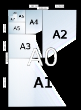
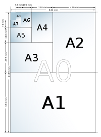
- ISO 216ISO 216ISO 216 specifies international standard paper sizes used in most countries in the world today. It defines the "A" and "B" series of paper sizes, including A4, the most commonly available size...
paper sizes, e.g. the A4 paper sizePaper sizeMany paper size standards conventions have existed at different times and in different countries. Today there is one widespread international ISO standard and a localised standard used in North America . The paper sizes affect writing paper, stationery, cards, and some printed documents... - ISO 406:1987 Technical drawings—Tolerancing of linear and angular dimensions
- ISO 1660:1987 Technical drawings—Dimensioning and tolerancing of profileProfile- Computing and technology :* Profile , a concept in Unified Modeling Language* Apple ProFile, a hard drive* User profile refers to the computer representation of user information...
s - ISO 2203:1973 Technical drawings—Conventional representation of gearGearA gear is a rotating machine part having cut teeth, or cogs, which mesh with another toothed part in order to transmit torque. Two or more gears working in tandem are called a transmission and can produce a mechanical advantage through a gear ratio and thus may be considered a simple machine....
s - ISO 3040:1990 Technical drawings—Dimensioning and tolerancing -- ConesCone (geometry)A cone is an n-dimensional geometric shape that tapers smoothly from a base to a point called the apex or vertex. Formally, it is the solid figure formed by the locus of all straight line segments that join the apex to the base...
- ISO 3098/1:1974 Technical Drawing - Lettering - Part I: Currently Used Characters
- ISO 4172:1991 Technical drawings -- Construction drawings -- Drawings for the assembly of prefabricated structures
- ISO 5261:1995 Technical drawings—Simplified representation of bars and profile sections
- ISO 5455:1979 Technical drawings—Scales
- ISO 5456 Technical drawings -- Projection methodOrthographic projectionOrthographic projection is a means of representing a three-dimensional object in two dimensions. It is a form of parallel projection, where all the projection lines are orthogonal to the projection plane, resulting in every plane of the scene appearing in affine transformation on the viewing surface...
s- ISO 5456-1:1996 Technical drawings—Projection methods—Part 1: Synopsis
- ISO 5456-2:1996 Technical drawings—Projection methods—Part 2: Orthographic representations
- ISO 5456-3:1996 Technical drawings—Projection methods—Part 3: Axonometric representations
- ISO 5456-4:1996 Technical drawings—Projection methods—Part 4: Central projection
- ISO 5457:1999 Technical product documentation -- Sizes and layout of drawing sheets
- ISO 5459:1981 Technical drawings -- Geometrical tolerancing -- Datums and datum-systems for geometrical tolerances
- ISO 5845-1:1995 Technical drawings—Simplified representation of the assembly of parts with fasteners—Part 1: General principles
- ISO 6410-1:1993 Technical drawings—Screw threadScrew threadA screw thread, often shortened to thread, is a helical structure used to convert between rotational and linear movement or force. A screw thread is a ridge wrapped around a cylinder or cone in the form of a helix, with the former being called a straight thread and the latter called a tapered thread...
s and threaded parts—Part 1: General conventions - ISO 6411:1982 Technical drawings—Simplified representation of centre holes
- ISO 6412-1:1989 Technical drawings—Simplified representation of pipelinePipeline transportPipeline transport is the transportation of goods through a pipe. Most commonly, liquids and gases are sent, but pneumatic tubes that transport solid capsules using compressed air are also used....
s -- Part 1: General rules and orthogonal representation - ISO 6413:1988 Technical drawings—Representation of splineSplineSpline can refer to:* Spline , a mating feature for rotating elements* Spline , a mathematical function used for interpolation or smoothing* Smoothing spline, a method of smoothing using a spline function...
s and serrationSerrationSerration generally refers to a saw-like appearance or a row of sharp or tooth-like projections. A serrated cutting edge has many small points of contact with the material being cut. By having less contact area than a smooth blade or other edge, the applied force at each point of contact is...
s - ISO 6414:1982 Technical drawings for glasswareGlasswareThis list of glassware includes drinking vessels , tableware, such as dishes, and flatware used to set a table for eating a meal, general glass items such as vases, and glasses used in the catering industry whether made of glass or plastics such as polystyrene and...
- ISO 6428:1982 Technical drawings—Requirements for microcopying
- ISO 6433:1981 Technical drawings -- Item references
- ISO 7200:1984 Technical drawings — Title blocks
- ISO 7083:1983 Technical drawings—Symbols for geometrical tolerancing -- Proportions and dimensions
- ISO 7437:1990 Technical drawings -- Construction drawings -- General rules for execution of production drawings for prefabricated structural components
- ISO 7518:1983 Technical drawings -- Construction drawings -- Simplified representation of demolition and rebuilding
- ISO 7519:1991 Technical drawings -- Construction drawings -- General principles of presentation for general arrangement and assembly drawings
- ISO 8015:1985 Technical drawings—Fundamental tolerancing principle
- ISO 8048:1984 Technical drawings -- Construction drawings -- Representation of views, sections and cuts
- ISO 8560:1986 Technical drawings -- Construction drawings -- Representation of modular sizes, lines and grids
- ISO 8560:1986 Technical drawings—Construction drawings—Representation of modular sizes, lines and grids
- ISO 8826-1:1989 Technical drawings—Rolling bearings—Part 1: General simplified representation
- ISO 8826-2:1994 Technical drawings—Rolling bearings—Part 2: Detailed simplified representation
- ISO 9222-1:1989 Technical drawings—Seals for dynamic application—Part 1: General simplified representation
- ISO 9222-2:1989 Technical drawings—Seals for dynamic application—Part 2: Detailed simplified representation
- ISO 9958-1:1992 Draughting media for technical drawings—Draughting film with polyester base—Part 1: Requirements and marking
- ISO 9961:1992 Draughting media for technical drawings—Natural tracing paper
- ISO 10209-1:1992 Technical product documentation—Vocabulary—Part 1: Terms relating to technical drawings: general and types of drawings
- ISO 10578:1992 Technical drawings—Tolerancing of orientation and location—Projected tolerance zone
- ISO 10579:1993 Technical drawings—Dimensioning and tolerancing—Non-rigid parts
- ISO 13567ISO 13567ISO 13567 is an international Computer-aided design layer standard.-Standard parts:The standard is divided in three parts:* ISO 13567-1:1998**Technical product documentation — Organization and naming of layers for CAD — Part 1: Overview and principles...
is an international Computer-aided designComputer-aided designComputer-aided design , also known as computer-aided design and drafting , is the use of computer technology for the process of design and design-documentation. Computer Aided Drafting describes the process of drafting with a computer...
(CAD) layer standard. - ISO 13715:2000 Technical drawings—Edges of undefined shape—Vocabulary and indications
- ISO 15786:2008 Technical drawings—Simplified representation and dimensioning of holes
See also
- List of ISO standards
- CAD standardsCAD standardsCAD Standards have been created to improve productivity and interchange of Computer-aided design documents between different offices and CAD programs, especially in architecture and engineering.- CAD layer standards :Most common:...
- ISO 216ISO 216ISO 216 specifies international standard paper sizes used in most countries in the world today. It defines the "A" and "B" series of paper sizes, including A4, the most commonly available size...
paper sizes, e.g. the A4A4A4, A04, A.IV, A.4 or A-4 may refer to:* A4 paper, a paper size prevalent in many countries , defined in the ISO 216 international standard...
paper sizePaper sizeMany paper size standards conventions have existed at different times and in different countries. Today there is one widespread international ISO standard and a localised standard used in North America . The paper sizes affect writing paper, stationery, cards, and some printed documents... - ISO 13567ISO 13567ISO 13567 is an international Computer-aided design layer standard.-Standard parts:The standard is divided in three parts:* ISO 13567-1:1998**Technical product documentation — Organization and naming of layers for CAD — Part 1: Overview and principles...
is an international Computer-aided designComputer-aided designComputer-aided design , also known as computer-aided design and drafting , is the use of computer technology for the process of design and design-documentation. Computer Aided Drafting describes the process of drafting with a computer...
(CAD) layer standard. - Engineering drawingEngineering drawingAn engineering drawing, a type of technical drawing, is used to fully and clearly define requirements for engineered items.Engineering drawing produces engineering drawings . More than just the drawing of pictures, it is also a language—a graphical language that communicates ideas and information...