
Components of jet engines
Encyclopedia
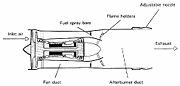
Jet engines are complicated devices that come in many forms, but have many components in common.
 The major components of a jet engine are similar across the major different types of engines, although not all engine types have all components. The major parts include:
The various components named above have constraints on how they are put together to generate the most efficiency or performance. The performance and efficiency of an engine can never be taken in isolation; for example fuel/distance efficiency of a supersonic jet engine maximises at about mach 2, whereas the drag for the vehicle carrying it is increasing as a square law and has much extra drag in the transonic region. The highest fuel efficiency for the overall vehicle is thus typically at Mach ~0.85.
For the engine optimisation for its intended use, important here is air intake design, overall size, number of compressor stages (sets of blades), fuel type, number of exhaust stages, metallurgy of components, amount of bypass air used, where the bypass air is introduced, and many other factors. For instance, let us consider design of the air intake.
 Pitot intakes are the dominant type for subsonic applications. A subsonic pitot inlet is little more than a tube with an aerodynamic fairing around it.
At zero airspeed (i.e., rest), air approaches the intake from a multitude of directions: from directly ahead, radially, or even from behind the plane of the intake lip.
At low airspeeds, the streamtube approaching the lip is larger in cross-section than the lip flow area, whereas at the intake design flight Mach number the two flow areas are equal. At high flight speeds the streamtube is smaller, with excess air spilling over the lip.
Beginning around Mach 0.85, shock waves can occur as the air accelerates through the intake throat.
Careful radiusing of the lip region is required to optimize intake pressure recovery (and distortion) throughout the flight envelope.
There are basically two forms of shock waves:
1) Normal shock waves lie perpendicular to the direction of the flow. These form sharp fronts and shock the flow to subsonic speeds. Microscopically the air molecules smash into the subsonic crowd of molecules like alpha rays. Normal shock waves tend to cause a large drop in stagnation pressure
. Basically, the higher the supersonic entry Mach number to a normal shock wave, the lower the subsonic exit Mach number and the stronger the shock (i.e. the greater the loss in stagnation pressure across the shock wave).
2) Conical (3-dimensional) and oblique shock waves (2D) are angled rearwards, like the bow wave on a ship or boat, and radiate from a flow disturbance such as a cone or a ramp. For a given inlet Mach number, they are weaker than the equivalent normal shock wave and, although the flow slows down, it remains supersonic throughout. Conical and oblique shock waves turn the flow, which continues in the new direction, until another flow disturbance is encountered downstream. Note: Comments made regarding 3 dimensional conical shock waves, generally also apply to 2D oblique shock waves.
A sharp-lipped version of the pitot intake, described above for subsonic applications, performs quite well at moderate supersonic flight speeds. A detached normal shock wave forms just ahead of the intake lip and 'shocks' the flow down to a subsonic velocity. However, as flight speed increases, the shock wave becomes stronger, causing a larger percentage decrease in stagnation pressure (i.e. poorer pressure recovery). An early US supersonic fighter, the F-100 Super Sabre
, used such an intake.
 More advanced supersonic intakes, excluding pitots:
a) exploit a combination of conical shock wave/s and a normal shock wave to improve pressure recovery at high supersonic flight speeds. Conical shock wave/s are used to reduce the supersonic Mach number at entry to the normal shock wave, thereby reducing the resultant overall shock losses.
b) have a design shock-on-lip flight Mach number, where the conical/oblique shock wave/s intercept the cowl lip, thus enabling the streamtube capture area to equal the intake lip area. However, below the shock-on-lip flight Mach number, the shock wave angle/s are less oblique, causing the streamline approaching the lip to be deflected by the presence of the cone/ramp. Consequently, the intake capture area is less than the intake lip area, which reduces the intake airflow. Depending on the airflow characteristics of the engine, it may be desirable to lower the ramp angle or move the cone rearwards to refocus the shockwaves onto the cowl lip to maximise intake airflow.
c) are designed to have a normal shock in the ducting downstream of intake lip, so that the flow at compressor/fan entry is always subsonic. However, if the engine is throttled back, there is a reduction in the corrected airflow of the LP compressor/fan, but (at supersonic conditions) the corrected airflow at the intake lip remains constant, because it is determined by the flight Mach number and intake incidence/yaw. This discontinuity is overcome by the normal shock moving to a lower cross-sectional area in the ducting, to decrease the Mach number at entry to the shockwave. This weakens the shockwave, improving the overall intake pressure recovery. So, the absolute airflow stays constant, whilst the corrected airflow at compressor entry falls (because of a higher entry pressure). Excess intake airflow may also be dumped overboard or into the exhaust system, to prevent the conical/oblique shock waves being disturbed by the normal shock being forced too far forward by engine throttling.
From another point of view, like in a supersonic nozzle the corrected (or non-dimensional) flow
has to be the same at the intake lip, at the intake throat and at the turbine. One of this three can be fixed. For inlets the throat is made variable and some air is bypassed around the turbine and directly fed into the afterburner. Unlike in a nozzle the inlet is either unstable or inefficient, because a normal shock wave in the throat will suddenly move to the lip, thereby increasing the pressure at the lip, leading to drag and reducing the pressure recovery, leading to turbine surge and the loss of one SR-71.
Many second generation supersonic fighter aircraft featured an inlet cone
, which was used to form the conical shock wave. This type of inlet cone is clearly seen at the very front of the English Electric Lightning
and MiG-21 aircraft, for example.
The same approach can be used for air intakes mounted at the side of the fuselage, where a half cone serves the same purpose with a semicircular air intake, as seen on the F-104 Starfighter
and BAC TSR-2
.
Some intakes are biconic; that is they feature two conical surfaces: the first cone is supplemented by a second, less oblique, conical surface, which generates an extra conical shockwave, radiating from the junction between the two cones. A biconic intake is usually more efficient than the equivalent conical intake, because the entry Mach number to the normal shock is reduced by the presence of the second conical shock wave.
A very sophisticated conical intake was featured on the SR-71's Pratt & Whitney J58
s that could move a conical spike
fore and aft within the engine nacelle, preventing the shockwave formed on the spike from entering the engine and stalling the engine, while keeping it close enough to give good compression. Movable cones are uncommon.
A more sophisticated design than cones is to angle the intake so that one of its edges forms a ramp. An oblique shockwave will form at the start of the ramp. The Century Series
of US jets featured several variants of this approach, usually with the ramp at the outer vertical edge of the intake, which was then angled back inward towards the fuselage. Typical examples include the Republic F-105 Thunderchief
and F-4 Phantom.
 Later this evolved so that the ramp was at the top horizontal edge rather than the outer vertical edge, with a pronounced angle downwards and rearwards. This design simplified the construction of intakes and allowed use of variable ramps to control airflow into the engine. Most designs since the early 1960s now feature this style of intake, for example the Grumman F-14 Tomcat, Panavia Tornado
and Concorde
.

 Axial compressors rely on spinning blades that have aerofoil sections, similar to aeroplane wings. As with aeroplane wings in some conditions the blades can stall. If this happens, the airflow around the stalled compressor can reverse direction violently. Each design of a compressor has an associated operating map of airflow versus rotational speed for characteristics peculiar to that type (see compressor map
).
At a given throttle condition, the compressor operates somewhere along the steady state running line. Unfortunately, this operating line is displaced during transients. Many compressors are fitted with anti-stall systems in the form of bleed bands or variable geometry stators to decrease the likelihood of surge. Another method is to split the compressor into two or more units, operating on separate concentric shafts.
Another design consideration is the average stage loading. This can be kept at a sensible level either by increasing the number of compression stages (more weight/cost) or the mean blade speed (more blade/disc stress).
Although large flow compressors are usually all-axial, the rear stages on smaller units are too small to be robust. Consequently, these stages are often replaced by a single centrifugal unit. Very small flow compressors often employ two centrifugal compressors, connected in series. Although in isolation centrifugal compressors are capable of running at quite high pressure ratios (e.g. 10:1), impeller stress considerations limit the pressure ratio that can be employed in high overall pressure ratio engine cycles.
Increasing overall pressure ratio implies raising the high pressure compressor exit temperature. This implies a higher high pressure shaft speed, to maintain the datum blade tip Mach number on the rear compressor stage. Stress considerations, however, may limit the shaft speed increase, causing the original compressor to throttle-back aerodynamically to a lower pressure ratio than datum.
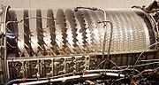
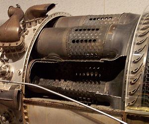 Flame fronts generally travel at just Mach 0.05, whereas airflows through jet engines are considerably faster than this. Combustors typically employ structures to give a sheltered combustion zone called a flame holder
. Combustor configurations include can, annular, and can-annular.
Great care must be taken to keep the flame burning in a moderately fast moving airstream, at all throttle conditions, as efficiently as possible. Since the turbine cannot withstand stoichiometric
temperatures (a mixture ratio of around 15:1), some of the compressor air is used to quench the exit temperature of the combustor to an acceptable level (an overall mixture ratio of between 45:1 and 130:1 is used). Air used for combustion is considered to be primary airflow, while excess air used for cooling is called secondary airflow. The secondary airflow is ported through many small holes in the burner cans to create a blanket of cooler air to insulate the metal surfaces of the combustion can from the flame. If the metal were subjected to the direct flame for any length of time, it would eventually burn through.
Rocket engines, being a non 'duct engine' have quite different combustor systems, and the mixture ratio is usually much closer to being stochiometric in the main chamber. These engines generally lack flame holders and combustion occurs at much higher temperatures, there being no turbine downstream. However, liquid rocket
engines frequently employ separate burners to power turbopumps, and these burners usually run far off stochiometric so as to lower turbine temperatures in the pump.
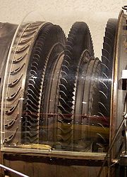 Because a turbine expands from high to low pressure, there is no such thing as turbine surge or stall. The turbine needs fewer stages than the compressor, mainly because the higher inlet temperature reduces the deltaT/T (and thereby the pressure ratio) of the expansion process. The blades have more curvature and the gas stream velocities are higher.
Designers must, however, prevent the turbine blades and vanes from melting in a very high temperature and stress environment. Consequently bleed air
extracted from the compression system is often used to cool the turbine blades/vanes internally. Other solutions are improved materials
and/or special insulating coatings
. The discs must be specially shaped to withstand the huge stresses
imposed by the rotating blades. They take the form of impulse, reaction, or combination impulse-reaction shapes. Improved materials help to keep disc weight down.
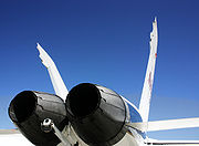
 Due to temperature limitations with the gas turbines, jet engines do not consume all the oxygen in the air ('run stoichiometric'). Afterburners burn the remaining oxygen after exiting the turbines, but usually do so inefficiently due to the low pressures typically found at this part of the jet engine make the subsequent nozzle inefficient at extracting the heat energy; however afterburners still gain significant thrust, which can be useful. Engines intended for extended use with afterburners often have variable nozzles and other details.
The primary objective of a nozzle is to use the heat and pressure of the exhaust gas to accelerate the jet to high speed so as to efficiently propel the vehicle. For air-breathing engines, if the fully expanded jet has a higher speed than the aircraft's airspeed, then there is a net rearward momentum gain to the air and there will be a forward thrust on the airframe.
Simple convergent nozzles are used on many jet engines. This forms a restricted opening which raises the pressure in the rest of the engine and increases the speed of the jet. However, if the nozzle pressure ratio is above the critical value (about 1.8:1) a convergent nozzle will 'choke', resulting in the jet being emitted at the speed of sound, higher pressure differences then gives much lower improvement in performance- although much of the gross thrust produced will still be from the jet momentum, some additional (pressure) thrust will come from the imbalance between the throat static pressure and atmospheric pressure.
Many military combat engines incorporate an afterburner (or reheat) in the engine exhaust system. When the system is lit, the nozzle throat area must be increased, to accommodate the extra exhaust volume flow, so that the turbo machinery is unaware that the afterburner is lit. A variable throat area is achieved by moving a series of overlapping petals, which approximate the circular nozzle cross-section.
At high nozzle pressure ratios, the exit pressure is often above ambient and much of the expansion will take place downstream of a convergent nozzle, which is inefficient. Consequently, some jet engines (notably rockets) incorporate a convergent-divergent nozzle, to allow most of the expansion to take place against the inside of a nozzle to maximize thrust. However, unlike the fixed con-div nozzle used on a conventional rocket motor
, when such a device is used on a turbojet engine it has to be a complex variable geometry device, to cope with the wide variation in nozzle pressure ratio encountered in flight and engine throttling. This further increases the weight and cost of such an installation.
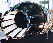
 The simpler of the two is the ejector nozzle, which creates an effective nozzle through a secondary airflow and spring-loaded petals. At subsonic speeds, the airflow constricts the exhaust to a convergent shape. As the aircraft speeds up, the two nozzles dilate, which allows the exhaust to form a convergent-divergent shape, speeding the exhaust gasses past Mach 1. More complex engines can actually use a tertiary airflow to reduce exit area at very low speeds. Advantages of the ejector nozzle are relative simplicity and reliability. Disadvantages are average performance (compared to the other nozzle type) and relatively high drag due to the secondary airflow. Notable aircraft to have utilized this type of nozzle include the SR-71, Concorde
, F-111, and Saab Viggen
For higher performance, it is necessary to use an iris nozzle. This type uses overlapping, hydraulically adjustable "petals". Although more complex than the ejector nozzle, it has significantly higher performance and smoother airflow. As such, it is employed primarily on high-performance fighters such as the F-14, F-15
, F-16, though is also used in high-speed bombers such as the B-1B. Some modern iris nozzles additionally have the ability to change the angle of the thrust (see thrust vectoring
).
 Rocket motors also employ convergent-divergent nozzles, but these are usually of fixed geometry, to minimize weight. Because of the much higher nozzle pressure ratios experienced, rocket motor con-di nozzles have a much greater area ratio (exit/throat) than those fitted to jet engines. The Convair F-106 Delta Dart has used such a nozzle design, as part of its overall design specification as an aerospace interceptor for high-altitude bomber interception, where conventional nozzle design would prove ineffective.
At the other extreme, some high bypass ratio
civil turbofan
s use an extremely low area ratio (less than 1.01 area ratio), convergent-divergent, nozzle on the bypass (or mixed exhaust) stream, to control the fan working line. The nozzle acts as if it has variable geometry. At low flight speeds the nozzle is unchoked (less than a Mach number
of unity), so the exhaust gas speeds up as it approaches the throat and then slows down slightly as it reaches the divergent section. Consequently, the nozzle exit area controls the fan match and, being larger than the throat, pulls the fan working line slightly away from surge. At higher flight speeds, the ram rise in the intake increases nozzle pressure ratio to the point where the throat becomes choked (M=1.0). Under these circumstances, the throat area dictates the fan match and being smaller than the exit pushes the fan working line slightly towards surge. This is not a problem, since fan surge margin is much better at high flight speeds.
Exhaust Nozzle:
The purpose of the exhaust nozzle is to increase the velocity of the exhaust gas before it discharge. For large values of thrust, the kinetic energy of the exhaust gas must be high, which implies a high exhaust velocity. The pressure ratio across the nozzle controls the expansion process and the maximum uninstalled thrust for a given engine is obtained when the exit pressure (Pe) equals the ambient pressure (P0) which is called as an optimum expansion.
The basic functions of the nozzles are:
Nozzle Types:=
The basic types of nozzles used in jet engines are:
The convergent nozzle is a simple convergent duct. When the nozzle pressure ratio (Pte/Po) is low (less than about 4), the convergent nozzle is used. The convergent nozzle has generally been used in engines for subsonic aircraft.
Convergent-divergent (C-D) nozzle.
The convergent-divergent nozzle is a convergent duct followed by a divergent duct. Where the cross-sectional area of the duct is
at a minimum, the nozzle is said to have a throat. Most convergent-divergent nozzles used in aircraft are not simple ducts, but
incorporate variable geometry and other aerodynamic features. The convergent-divergent nozzle is used if the nozzle pressure ratio
is high (greater than about four). High-performance engines in supersonic aircraft generally have some form of a convergent
divergent nozzle. If the engine incorporates an afterburner, the nozzle throat is usually scheduled to leave the operating
conditions of the engine upstream of the afterburner unchanged. Also, the exit area must be varied to match the internal and
external static pressures at exit for different flow conditions in order to produce the maximum available uninstalled thrust.
For the modem high-performance afterburning turbofan engines, simple convergent-divergent nozzles are used without secondary air.
Nozzle Functions:=
The nozzle serves as a back-pressure control for the engine and an acceleration device converting gas thermal energy into kinetic energy. A secondary function of the nozzle is providing required thrust reversing and/or thrust vectoring. The nozzle design can also reduce the infrared signature of the engine.
Large changes in exhaust nozzle throat area are required for after burning engines to compensate for the large changes in total temperature leaving the afterburner. The variable-area nozzle required for an after burning engine can also be used for back-pressure control at its non-after burning settings. One advantage of the variable-area exhaust nozzle is that it improves the starting of the engine. Opening the nozzle throat area to its maximum value reduces the back-pressure on the turbine and increases its expansion ratio. Thus, the necessary turbine power for starting operation may be produced at a lower turbine inlet temperature. Also, since the back-pressure on the gas generator is reduced, the compressor may be started at a lower engine speed, which reduces the required size of the engine starter.
Gross thrust coefficient: The gross thrust coefficient (Cfg) is defined as the ratio of the actual gross thrust (Fgactual) to the ideal gross thrust (Fg ideal).
C f g = Fg actual/ Fg ideal
Discharge flow coefficient: The ratio of the actual mass flow (m8 ) to the ideal mass flow (m8i) is called the discharge coefficient (CD)
CD = m8/m8i
Mass flow parameter
Assume value of CD and calculate actual flow area required and on Area ratio calculate the exit area of nozzle.
Using gas table using Critical Area ratio calculate Mach no and Pressure ratio
Calculate ideal exit velocity
Calculate actual exit velocity
Calculate velocity coefficient
Calculate Nozzle thrust coefficient
Calculate gross thrust
Cooling systems are employed to keep the temperature of the solid parts below the failure temperature.
Air, bled from the compressor exit, passes around the combustor and is injected into the rim of the rotating turbine disc. The cooling air then passes through complex passages within the turbine blades. After removing heat from the blade material, the air (now fairly hot) is vented, via cooling holes, into the main gas stream. Cooling air for the turbine vanes undergoes a similar process.
Cooling the leading edge of the blade can be difficult, because the pressure of the cooling air just inside the cooling hole may not be much different from that of the oncoming gas stream. One solution is to incorporate a cover plate on the disc. This acts as a centrifugal compressor to pressurize the cooling air before it enters the blade. Another solution is to use an ultra-efficient turbine rim seal to pressurize the area where the cooling air passes across to the rotating disc.
Seals are used to prevent oil leakage, control air for cooling and prevent stray air flows into turbine cavities.
A series of (e.g. labyrinth) seals allow a small flow of bleed air to wash the turbine disc to extract heat and, at the same time, pressurize the turbine rim seal, to prevent hot gases entering the inner part of the engine.
Other types of seals are hydraulic, brush, carbon etc.
Small quantities of compressor bleed air are also used to cool the shaft, turbine shrouds, etc.
Some air is also used to keep the temperature of the combustion chamber walls below critical. This is done using primary and secondary airholes which allow a thin layer of air to cover the inner walls of the chamber preventing excessive heating.
Exit temperature is dependent on the turbine upper temperature limit depending on the material. Reducing the temperature will also prevent thermal fatigue and hence failure.
Accessories may also need their own cooling systems using air from the compressor or outside air.
Air from compressor stages is also used for heating of the fan, airframe anti-icing and for cabin heat. Which stage is bled from depends on the atmospheric conditions at that altitude.
So the sequence of events for increasing thrust is, the throttle opens and fuel spray pressure is increased, increasing the amount of fuel being burned. This means that exhaust gases are hotter and so are ejected at higher acceleration, which means they exert higher forces and therefore increase the engine thrust directly. It also increases the energy extracted by the turbine which drives the compressor even faster and so there is an increase in air flowing into the engine as well.
Obviously, it is the rate of the mass of the airflow that matters since it is the change in momentum (mass x velocity) that produces the force. However, density varies with altitude and hence inflow of mass will also vary with altitude, temperature etc. which means that throttle values will vary according to all these parameters without changing them manually.
This is why fuel flow is controlled automatically. Usually there are 2 systems, one to control the pressure and the other to control the flow. The inputs are usually from pressure and temperature probes from the intake and at various points through the engine. Also throttle inputs, engine speed etc. are required. These affect the high pressure fuel pump.
Take the possibility of increased altitude where there will be reduced air intake pressure. In this case, the chamber within the FCU will expand which causes the spill valve to bleed more fuel. This causes the pump to deliver less fuel until the opposing chamber pressure is equivalent to the air pressure and the spill valve goes back to its position.
When the throttle is opened, it releases i.e. lessens the pressure which lets the throttle valve fall. The pressure is transmitted (because of a back-pressure valve i.e. no air gaps in fuel flow) which closes the FCU spill valves (as they are commonly called) which then increases the pressure and causes a higher flow rate.
The engine speed governor is used to prevent the engine from over-speeding. It has the capability of disregarding the FCU control. It does this by use of a diaphragm which senses the engine speed in terms of the centrifugal pressure caused by the rotating rotor of the pump. At a critical value, this diaphragm causes another spill valve to open and bleed away the fuel flow.
There are other ways of controlling fuel flow for example with the dash-pot throttle lever. The throttle has a gear which meshes with the control valve (like a rack and pinion) causing it to slide along a cylinder which has ports at various positions. Moving the throttle and hence sliding the valve along the cylinder, opens and closes these ports as designed. There are actually 2 valves viz. the throttle and the control valve. The control valve is used to control pressure on one side of the throttle valve such that it gives the right opposition to the throttle control pressure. It does this by controlling the fuel outlet from within the cylinder.
So for example, if the throttle valve is moved up to let more fuel in, it will mean that the throttle valve has moved into a position which allows more fuel to flow through and on the other side, the required pressure ports are opened to keep the pressure balance so that the throttle lever stays where it is.
At initial acceleration, more fuel is required and the unit is adapted to allow more fuel to flow by opening other ports at a particular throttle position. Changes in pressure of outside air i.e. altitude, speed of aircraft etc. are sensed by an air capsule.
) staged combustion
is used, and the pump gas exhaust is returned into the main chamber where the combustion is completed and essentially no loss of performance due to pumping losses then occurs.
Ramjet turbopumps use ram air expanding through a turbine.
is used to start the engines. It has a starter motor which has a high torque transmitted to the compressor unit. When the optimum speed is reached, i.e. the flow of gas through the turbine is sufficient, the turbines take over.
There are a number of different starting methods such as electric, hydraulic, pneumatic etc.
The electric starter works with gears and clutch plate linking the motor and the engine. The clutch is used to disengage when optimum speed is achieved. This is usually done automatically. The electric supply is used to start the motor as well as for ignition. The voltage is usually built up slowly as starter gains speed.
Some military aircraft need to be started quicker than the electric method permits and hence they use other methods such as a cartridge turbine starter or "cart starter". This is an impulse turbine impacted by burning gases from a cartridge, usually created by igniting a solid propellant similar to gun powder. It is geared to rotate the engine and also connected to an automatic disconnect system, or overrunning clutch. The cartridge is set alight electrically and used to turn the starter's turbine.
Another turbine starter system is almost exactly like a little engine. Again the turbine is connected to the engine via gears. However, the turbine is turned by burning gases - usually the fuel is isopropyl nitrate
(or sometimes Hydrazine) stored in a tank and sprayed into a combustion chamber. Again, it is ignited with a spark plug. Everything is electrically controlled, such as speed etc.
Most Commercial aircraft and large Military Transport airplanes usually use what is called an auxiliary power unit
or APU. It is normally a small gas turbine. Thus, one could say that using such an APU is using a small gas turbine to start a larger one. Low pressure (40-70 psi), high volume air from the compressor section of the APU is bled off through a system of pipes to the engines where it is directed into the starting system. This "bleed air" is directed into a mechanism to start the engine turning and begin pulling in air. The starter is usually an "air turbine" type, similar to the cartridge starter, but uses APU's bleed air instead of the burning gases of the propellant cartridge. Most cart starters can also use APU air to turn them. When the rotating speed of the engine is sufficient to pull in enough air to support combustion, fuel is introduced and ignited. Once the engine ignites and reaches idle speed, the bleed air and ignition systems are shut off.
The APUs on aircraft such as the Boeing 737
and Airbus A320
can be seen at the extreme rear of the aircraft. This is the typical location for an APU on most commercial airliners although some may be within the wing root (Boeing 727
) or the aft fuselage (DC-9/MD80) as examples and some military transports carry their APU's in one of the main landing gear pods (C-141).
Some APUs are mounted on wheeled carts, so they can be towed and used on different aircraft. They are connected by a hose to the aircraft ducting, which includes a check valve to allow the APU air to flow into the aircraft, while not allowing the main engine's bleed air to exit through the duct.
The APUs also provide enough power to keep the cabin lights, pressure and other systems on while the engines are off. The valves used to control the airflow are usually electrically controlled. They automatically close at a pre-determined speed. As part of the starting sequence on some engines fuel is combined with the supplied air and burned instead of using just air. This usually produces more power per unit weight.
Usually an APU is started by its own electric starter motor which is switched off at the proper speed automatically. When the main engine starts up and reaches the right conditions, this auxiliary unit is then switched off and disengages slowly.
Hydraulic pumps can also be used to start some engines through gears. The pumps are electrically controlled on the ground.
A variation of this is the APU installed in a Boeing F/A-18 Hornet; it is started by a hydraulic motor, which itself receives energy stored in an accumulator. This accumulator is recharged after the right engine is started and develops hydraulic pressure, or by a hand pump in the right hand main landing gear well.
For example, the General Electric F404-400 uses one ignitor for the combustor and one for the afterburner; the ignition system for the A/B incorporates an ultraviolet flame sensor to activate the ignitor.
Most modern ignition systems provide enough energy (20-40,000 volts) to be a lethal hazard should a person be in contact with the electrical lead when the system is activated, so team communication is vital when working on these systems.
The lubricant is isolated from the external parts of the engine through various sealing mechanisms, which also prevent dirt and other foreign objects from contaminating the oil and from reaching the bearings, gears, and other moving parts, and typically flows in a loop (is not intentionally consumed through engine usage). The lubricant must be able to flow easily at relatively low temperatures and not disintegrate or break down at very high temperatures.
Usually the lubrication system has subsystems that deal individually with the lubrication supply system of an engine, scavenging (oil return system), and a breather (venting excess air from internal compartments).
The pressure system components are typically include an oil tank and de-aerator, main oil pump, main oil filter/filter bypass valve, pressure regulating valve (PRV), oil cooler/by pass valve and tubing/jets.
Usually the flow is from the tank to the pump inlet and PRV, pumped to main oil filter or its bypass valve and oil cooler, then through some more filters to jets in the bearings.
Using the PRV method of control, means that the pressure of the feed oil must be below a critical value (usually controlled by other valves which can leak out excess oil back to tank if it exceeds the critical value). The valve opens at a certain pressure and oil is kept moving at a constant rate into the bearing chamber.
If the engine power setting increases, the pressure within the bearing chamber also typically increases, which means the pressure difference between the lubricant feed and the chamber reduces which could reduce slow rate of oil when it is needed even more. As a result, some PRVs can adjust their spring force values using this pressure change in the bearing chamber proportionally to keep the lubricant flow constant.
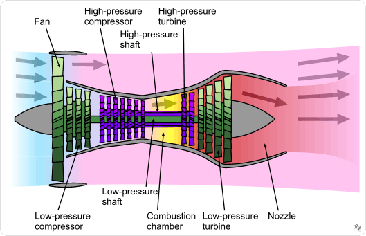
Major components
- Cold Section:
- Air intake (Inlet) — The standard reference frameReference frameReference frame may refer to:*Frame of reference, in physics*Reference frame , frames of a compressed video that are used to define future frames...
for a jet engine is the aircraft itself. For subsonic aircraft, the air intake to a jet engine presents no special difficulties, and consists essentially of an opening which is designed to minimise drag, as with any other aircraft component. However, the air reaching the compressor of a normal jet engine must be travelling below the speed of sound, even for supersonic aircraft, to sustain the flow mechanics of the compressor and turbine blades. At supersonic flight speeds, shockwaves form in the intake system and reduce the recovered pressure at inlet to the compressor. So some supersonic intakes use devices, such as a cone or ramp, to increase pressure recovery, by making more efficient use of the shock wave system. - CompressorGas compressorA gas compressor is a mechanical device that increases the pressure of a gas by reducing its volume.Compressors are similar to pumps: both increase the pressure on a fluid and both can transport the fluid through a pipe. As gases are compressible, the compressor also reduces the volume of a gas...
or FanFan (mechanical)A mechanical fan is a machine used to create flow within a fluid, typically a gas such as air.A fan consists of a rotating arrangement of vanes or blades which act on the air. Usually, it is contained within some form of housing or case. This may direct the airflow or increase safety by preventing...
— The compressor is made up of stages. Each stage consists of vanes which rotate, and stators which remain stationary. As air is drawn deeper through the compressor, its heat and pressure increases. Energy is derived from the turbine (see below), passed along the shaft. - Bypass ducts much of the thrust of essentially all modern jet engines comes from air from the front compressor that bypasses the combustion chamber and gas turbine section that leads directly to the nozzle or afterburner (where fitted).
- Air intake (Inlet) — The standard reference frame
- Common:
- Shaft — The shaft connects the turbine to the compressor, and runs most of the length of the engine. There may be as many as three concentric shafts, rotating at independent speeds, with as many sets of turbines and compressors. Other services, like a bleed of cool air, may also run down the shaft.
- Diffuser section: - This section is a divergent duct that utilizes Bernoulli's principle to decrease the velocity of the compressed air to allow for easier ignition. And, at the same time, continuing to increase the air pressure before it enters the combustion chamber.
- Hot section:
- CombustorCombustorA combustor is a component or area of a gas turbine, ramjet, or scramjet engine where combustion takes place. It is also known as a burner, combustion chamber or flame holder. In a gas turbine engine, the combustor or combustion chamber is fed high pressure air by the compression system. The...
or Can or FlameholdersFlame holderA flame holder is a component of a jet engine designed to help maintain continual combustion.All continuous-combustion jet engines require a flame holder. A flame holder creates a low-speed eddy in the engine to prevent the flame from being blown out...
or Combustion Chamber — This is a chamber where fuel is continuously burned in the compressed air. - TurbineTurbineA turbine is a rotary engine that extracts energy from a fluid flow and converts it into useful work.The simplest turbines have one moving part, a rotor assembly, which is a shaft or drum with blades attached. Moving fluid acts on the blades, or the blades react to the flow, so that they move and...
— The turbine is a series of bladed discs that act like a windmill, gaining energy from the hot gases leaving the combustor. Some of this energy is used to drive the compressor, and in some turbine engines (i.e. turboprop, turboshaft or turbofan engines), energy is extracted by additional turbine discs and used to drive devices such as propellers, bypass fans or helicopter rotors. One type, a free turbine, is configured such that the turbine disc driving the compressor rotates independently of the discs that power the external components. Relatively cool air, bled from the compressor, may be used to cool the turbine blades and vanes, to prevent them from melting. - AfterburnerAfterburner (engine)An afterburner is an additional component added to some jet engines, primarily those on military supersonic aircraft. Its purpose is to provide a temporary increase in thrust, both for supersonic flight and for takeoff...
or reheat (chiefly UK) — (mainly military) Produces extra thrust by burning extra fuel, usually inefficiently, to significantly raise Nozzle Entry Temperature at the exhaust. Owing to a larger volume flow (i.e. lower density) at exit from the afterburner, an increased nozzle flow area is required, to maintain satisfactory engine matching, when the afterburner is alight. - Exhaust or NozzleNozzleA nozzle is a device designed to control the direction or characteristics of a fluid flow as it exits an enclosed chamber or pipe via an orifice....
— Hot gases leaving the engine exhaust to atmospheric pressure via a nozzle, the objective being to produce a high velocity jet. In most cases, the nozzle is convergent and of fixed flow area. - Supersonic nozzle — If the Nozzle Pressure Ratio (Nozzle Entry Pressure/Ambient Pressure) is very high, to maximize thrust it may be worthwhile, despite the additional weight, to fit a convergent-divergent (de Laval) nozzleDe Laval nozzleA de Laval nozzle is a tube that is pinched in the middle, making a carefully balanced, asymmetric hourglass-shape...
. As the name suggests, initially this type of nozzle is convergent, but beyond the throat (smallest flow area), the flow area starts to increase to form the divergent portion. The expansion to atmospheric pressure and supersonic gas velocity continues downstream of the throat, whereas in a convergent nozzle the expansion beyond sonic velocity occurs externally, in the exhaust plume. The former process is more efficient than the latter.
- Combustor
The various components named above have constraints on how they are put together to generate the most efficiency or performance. The performance and efficiency of an engine can never be taken in isolation; for example fuel/distance efficiency of a supersonic jet engine maximises at about mach 2, whereas the drag for the vehicle carrying it is increasing as a square law and has much extra drag in the transonic region. The highest fuel efficiency for the overall vehicle is thus typically at Mach ~0.85.
For the engine optimisation for its intended use, important here is air intake design, overall size, number of compressor stages (sets of blades), fuel type, number of exhaust stages, metallurgy of components, amount of bypass air used, where the bypass air is introduced, and many other factors. For instance, let us consider design of the air intake.
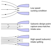
Subsonic inlets
At zero airspeed (i.e., rest), air approaches the intake from a multitude of directions: from directly ahead, radially, or even from behind the plane of the intake lip.
At low airspeeds, the streamtube approaching the lip is larger in cross-section than the lip flow area, whereas at the intake design flight Mach number the two flow areas are equal. At high flight speeds the streamtube is smaller, with excess air spilling over the lip.
Beginning around Mach 0.85, shock waves can occur as the air accelerates through the intake throat.
Careful radiusing of the lip region is required to optimize intake pressure recovery (and distortion) throughout the flight envelope.
Supersonic inlets
Supersonic intakes exploit shock waves to decelerate the airflow to a subsonic condition at compressor entry.There are basically two forms of shock waves:
1) Normal shock waves lie perpendicular to the direction of the flow. These form sharp fronts and shock the flow to subsonic speeds. Microscopically the air molecules smash into the subsonic crowd of molecules like alpha rays. Normal shock waves tend to cause a large drop in stagnation pressure
Stagnation pressure
In fluid dynamics, stagnation pressure is the static pressure at a stagnation point in a fluid flow.At a stagnation point the fluid velocity is zero and all kinetic energy has been converted into pressure energy . Stagnation pressure is equal to the sum of the free-stream dynamic pressure and...
. Basically, the higher the supersonic entry Mach number to a normal shock wave, the lower the subsonic exit Mach number and the stronger the shock (i.e. the greater the loss in stagnation pressure across the shock wave).
2) Conical (3-dimensional) and oblique shock waves (2D) are angled rearwards, like the bow wave on a ship or boat, and radiate from a flow disturbance such as a cone or a ramp. For a given inlet Mach number, they are weaker than the equivalent normal shock wave and, although the flow slows down, it remains supersonic throughout. Conical and oblique shock waves turn the flow, which continues in the new direction, until another flow disturbance is encountered downstream. Note: Comments made regarding 3 dimensional conical shock waves, generally also apply to 2D oblique shock waves.
A sharp-lipped version of the pitot intake, described above for subsonic applications, performs quite well at moderate supersonic flight speeds. A detached normal shock wave forms just ahead of the intake lip and 'shocks' the flow down to a subsonic velocity. However, as flight speed increases, the shock wave becomes stronger, causing a larger percentage decrease in stagnation pressure (i.e. poorer pressure recovery). An early US supersonic fighter, the F-100 Super Sabre
F-100 Super Sabre
The North American F-100 Super Sabre was a supersonic jet fighter aircraft that served with the United States Air Force from 1954 to 1971 and with the Air National Guard until 1979. The first of the Century Series collection of USAF jet fighters, it was the first USAF fighter capable of...
, used such an intake.
a) exploit a combination of conical shock wave/s and a normal shock wave to improve pressure recovery at high supersonic flight speeds. Conical shock wave/s are used to reduce the supersonic Mach number at entry to the normal shock wave, thereby reducing the resultant overall shock losses.
b) have a design shock-on-lip flight Mach number, where the conical/oblique shock wave/s intercept the cowl lip, thus enabling the streamtube capture area to equal the intake lip area. However, below the shock-on-lip flight Mach number, the shock wave angle/s are less oblique, causing the streamline approaching the lip to be deflected by the presence of the cone/ramp. Consequently, the intake capture area is less than the intake lip area, which reduces the intake airflow. Depending on the airflow characteristics of the engine, it may be desirable to lower the ramp angle or move the cone rearwards to refocus the shockwaves onto the cowl lip to maximise intake airflow.
c) are designed to have a normal shock in the ducting downstream of intake lip, so that the flow at compressor/fan entry is always subsonic. However, if the engine is throttled back, there is a reduction in the corrected airflow of the LP compressor/fan, but (at supersonic conditions) the corrected airflow at the intake lip remains constant, because it is determined by the flight Mach number and intake incidence/yaw. This discontinuity is overcome by the normal shock moving to a lower cross-sectional area in the ducting, to decrease the Mach number at entry to the shockwave. This weakens the shockwave, improving the overall intake pressure recovery. So, the absolute airflow stays constant, whilst the corrected airflow at compressor entry falls (because of a higher entry pressure). Excess intake airflow may also be dumped overboard or into the exhaust system, to prevent the conical/oblique shock waves being disturbed by the normal shock being forced too far forward by engine throttling.
From another point of view, like in a supersonic nozzle the corrected (or non-dimensional) flow
Corrected flow
Corrected Flow is the mass flow that would pass through a device if the inlet pressure and temperature corresponded to ambient conditions at Sea Level, on a Standard Day Corrected Flow is the mass flow that would pass through a device (e.g. compressor, bypass duct, etc.) if the inlet pressure and...
has to be the same at the intake lip, at the intake throat and at the turbine. One of this three can be fixed. For inlets the throat is made variable and some air is bypassed around the turbine and directly fed into the afterburner. Unlike in a nozzle the inlet is either unstable or inefficient, because a normal shock wave in the throat will suddenly move to the lip, thereby increasing the pressure at the lip, leading to drag and reducing the pressure recovery, leading to turbine surge and the loss of one SR-71.
Inlet cone
Many second generation supersonic fighter aircraft featured an inlet cone
Inlet cone
Inlet cones are a component of some supersonic aircraft. They are primarily used on ramjets, such as the turboramjets of the SR-71 or the pure ramjets of the D-21 Tagboard and Lockheed X-7...
, which was used to form the conical shock wave. This type of inlet cone is clearly seen at the very front of the English Electric Lightning
English Electric Lightning
The English Electric Lightning is a supersonic jet fighter aircraft of the Cold War era, noted for its great speed and unpainted natural metal exterior finish. It is the only all-British Mach 2 fighter aircraft. The aircraft was renowned for its capabilities as an interceptor; Royal Air Force ...
and MiG-21 aircraft, for example.
The same approach can be used for air intakes mounted at the side of the fuselage, where a half cone serves the same purpose with a semicircular air intake, as seen on the F-104 Starfighter
F-104 Starfighter
The Lockheed F-104 Starfighter is a single-engine, high-performance, supersonic interceptor aircraft originally developed for the United States Air Force by Lockheed. One of the Century Series of aircraft, it served with the USAF from 1958 until 1969, and continued with Air National Guard units...
and BAC TSR-2
BAC TSR-2
The British Aircraft Corporation TSR-2 was a cancelled Cold War strike and reconnaissance aircraft developed by the British Aircraft Corporation for the Royal Air Force in the late 1950s and early 1960s...
.
Some intakes are biconic; that is they feature two conical surfaces: the first cone is supplemented by a second, less oblique, conical surface, which generates an extra conical shockwave, radiating from the junction between the two cones. A biconic intake is usually more efficient than the equivalent conical intake, because the entry Mach number to the normal shock is reduced by the presence of the second conical shock wave.
A very sophisticated conical intake was featured on the SR-71's Pratt & Whitney J58
Pratt & Whitney J58
The Pratt & Whitney J58 was a jet engine used on the Lockheed A-12, and subsequently on the YF-12 and SR-71 Blackbird aircraft. The J58 was a variable cycle engine which functioned as both a turbojet and a fan-assisted ramjet. The J58 was a single-spool turbojet engine with an afterburner...
s that could move a conical spike
Inlet cone
Inlet cones are a component of some supersonic aircraft. They are primarily used on ramjets, such as the turboramjets of the SR-71 or the pure ramjets of the D-21 Tagboard and Lockheed X-7...
fore and aft within the engine nacelle, preventing the shockwave formed on the spike from entering the engine and stalling the engine, while keeping it close enough to give good compression. Movable cones are uncommon.
Inlet ramp
A more sophisticated design than cones is to angle the intake so that one of its edges forms a ramp. An oblique shockwave will form at the start of the ramp. The Century Series
Century series
The Century Series is a popular name for a group of US fighter aircraft representing models designated between F-100 and F-106 which went into full production...
of US jets featured several variants of this approach, usually with the ramp at the outer vertical edge of the intake, which was then angled back inward towards the fuselage. Typical examples include the Republic F-105 Thunderchief
F-105 Thunderchief
The Republic F-105 Thunderchief, was a supersonic fighter-bomber used by the United States Air Force. The Mach 2 capable F-105 conducted the majority of strike bombing missions during the early years of the Vietnam War; it has the dubious distinction of being the only US aircraft to have been...
and F-4 Phantom.
Panavia Tornado
The Panavia Tornado is a family of twin-engine, variable-sweep wing combat aircraft, which was jointly developed and manufactured by the United Kingdom, West Germany and Italy...
and Concorde
Concorde
Aérospatiale-BAC Concorde was a turbojet-powered supersonic passenger airliner, a supersonic transport . It was a product of an Anglo-French government treaty, combining the manufacturing efforts of Aérospatiale and the British Aircraft Corporation...
.
Compressors
Compressor map
Each compressor in a gas turbine engine has an operating map. Complete maps are either based on compressor rig test results or are predicted by a special computer program...
).
At a given throttle condition, the compressor operates somewhere along the steady state running line. Unfortunately, this operating line is displaced during transients. Many compressors are fitted with anti-stall systems in the form of bleed bands or variable geometry stators to decrease the likelihood of surge. Another method is to split the compressor into two or more units, operating on separate concentric shafts.
Another design consideration is the average stage loading. This can be kept at a sensible level either by increasing the number of compression stages (more weight/cost) or the mean blade speed (more blade/disc stress).
Although large flow compressors are usually all-axial, the rear stages on smaller units are too small to be robust. Consequently, these stages are often replaced by a single centrifugal unit. Very small flow compressors often employ two centrifugal compressors, connected in series. Although in isolation centrifugal compressors are capable of running at quite high pressure ratios (e.g. 10:1), impeller stress considerations limit the pressure ratio that can be employed in high overall pressure ratio engine cycles.
Increasing overall pressure ratio implies raising the high pressure compressor exit temperature. This implies a higher high pressure shaft speed, to maintain the datum blade tip Mach number on the rear compressor stage. Stress considerations, however, may limit the shaft speed increase, causing the original compressor to throttle-back aerodynamically to a lower pressure ratio than datum.
Combustors
Flame holder
A flame holder is a component of a jet engine designed to help maintain continual combustion.All continuous-combustion jet engines require a flame holder. A flame holder creates a low-speed eddy in the engine to prevent the flame from being blown out...
. Combustor configurations include can, annular, and can-annular.
Great care must be taken to keep the flame burning in a moderately fast moving airstream, at all throttle conditions, as efficiently as possible. Since the turbine cannot withstand stoichiometric
Stoichiometry
Stoichiometry is a branch of chemistry that deals with the relative quantities of reactants and products in chemical reactions. In a balanced chemical reaction, the relations among quantities of reactants and products typically form a ratio of whole numbers...
temperatures (a mixture ratio of around 15:1), some of the compressor air is used to quench the exit temperature of the combustor to an acceptable level (an overall mixture ratio of between 45:1 and 130:1 is used). Air used for combustion is considered to be primary airflow, while excess air used for cooling is called secondary airflow. The secondary airflow is ported through many small holes in the burner cans to create a blanket of cooler air to insulate the metal surfaces of the combustion can from the flame. If the metal were subjected to the direct flame for any length of time, it would eventually burn through.
Rocket engines, being a non 'duct engine' have quite different combustor systems, and the mixture ratio is usually much closer to being stochiometric in the main chamber. These engines generally lack flame holders and combustion occurs at much higher temperatures, there being no turbine downstream. However, liquid rocket
Liquid rocket
A liquid-propellant rocket or a liquid rocket is a rocket engine that uses propellants in liquid form. Liquids are desirable because their reasonably high density allows the volume of the propellant tanks to be relatively low, and it is possible to use lightweight pumps to pump the propellant from...
engines frequently employ separate burners to power turbopumps, and these burners usually run far off stochiometric so as to lower turbine temperatures in the pump.
Turbines
Designers must, however, prevent the turbine blades and vanes from melting in a very high temperature and stress environment. Consequently bleed air
Bleed air
Bleed air in gas turbine engines is compressed air taken from within the engine, after the compressor stage and before the fuel is injected in the burners. While in theory bleed air could be drawn in any gas turbine engine, its usage is generally restricted to jet engines used in aircraft...
extracted from the compression system is often used to cool the turbine blades/vanes internally. Other solutions are improved materials
Superalloy
A superalloy, or high-performance alloy, is an alloy that exhibits excellent mechanical strength and creep resistance at high temperatures, good surface stability, and corrosion and oxidation resistance. Superalloys typically have a matrix with an austenitic face-centered cubic crystal structure. ...
and/or special insulating coatings
Abradable coating
An abradable coating is a coating made of an abradable material – meaning if it rubs against a more abrasive material in motion, the former will be worn whereas the latter will face no wear....
. The discs must be specially shaped to withstand the huge stresses
Stress (physics)
In continuum mechanics, stress is a measure of the internal forces acting within a deformable body. Quantitatively, it is a measure of the average force per unit area of a surface within the body on which internal forces act. These internal forces are a reaction to external forces applied on the body...
imposed by the rotating blades. They take the form of impulse, reaction, or combination impulse-reaction shapes. Improved materials help to keep disc weight down.
Afterburners (reheat)
Nozzles
The primary objective of a nozzle is to use the heat and pressure of the exhaust gas to accelerate the jet to high speed so as to efficiently propel the vehicle. For air-breathing engines, if the fully expanded jet has a higher speed than the aircraft's airspeed, then there is a net rearward momentum gain to the air and there will be a forward thrust on the airframe.
Simple convergent nozzles are used on many jet engines. This forms a restricted opening which raises the pressure in the rest of the engine and increases the speed of the jet. However, if the nozzle pressure ratio is above the critical value (about 1.8:1) a convergent nozzle will 'choke', resulting in the jet being emitted at the speed of sound, higher pressure differences then gives much lower improvement in performance- although much of the gross thrust produced will still be from the jet momentum, some additional (pressure) thrust will come from the imbalance between the throat static pressure and atmospheric pressure.
Many military combat engines incorporate an afterburner (or reheat) in the engine exhaust system. When the system is lit, the nozzle throat area must be increased, to accommodate the extra exhaust volume flow, so that the turbo machinery is unaware that the afterburner is lit. A variable throat area is achieved by moving a series of overlapping petals, which approximate the circular nozzle cross-section.
At high nozzle pressure ratios, the exit pressure is often above ambient and much of the expansion will take place downstream of a convergent nozzle, which is inefficient. Consequently, some jet engines (notably rockets) incorporate a convergent-divergent nozzle, to allow most of the expansion to take place against the inside of a nozzle to maximize thrust. However, unlike the fixed con-div nozzle used on a conventional rocket motor
Rocket engine nozzles
A rocket engine nozzle is a propelling nozzle used in a rocket engine to expand and accelerate the combustion gases produced by burning propellants so that the exhaust gases exit the nozzle at hypersonic velocities.-History:...
, when such a device is used on a turbojet engine it has to be a complex variable geometry device, to cope with the wide variation in nozzle pressure ratio encountered in flight and engine throttling. This further increases the weight and cost of such an installation.
Concorde
Aérospatiale-BAC Concorde was a turbojet-powered supersonic passenger airliner, a supersonic transport . It was a product of an Anglo-French government treaty, combining the manufacturing efforts of Aérospatiale and the British Aircraft Corporation...
, F-111, and Saab Viggen
For higher performance, it is necessary to use an iris nozzle. This type uses overlapping, hydraulically adjustable "petals". Although more complex than the ejector nozzle, it has significantly higher performance and smoother airflow. As such, it is employed primarily on high-performance fighters such as the F-14, F-15
F-15 Eagle
The McDonnell Douglas F-15 Eagle is a twin-engine, all-weather tactical fighter designed by McDonnell Douglas to gain and maintain air superiority in aerial combat. It is considered among the most successful modern fighters with over 100 aerial combat victories with no losses in dogfights...
, F-16, though is also used in high-speed bombers such as the B-1B. Some modern iris nozzles additionally have the ability to change the angle of the thrust (see thrust vectoring
Thrust vectoring
Thrust vectoring, also thrust vector control or TVC, is the ability of an aircraft, rocket or other vehicle to manipulate the direction of the thrust from its engine or motor in order to control the attitude or angular velocity of the vehicle....
).
At the other extreme, some high bypass ratio
Bypass ratio
The term bypass ratio relates to the design of turbofan engines, commonly used in aviation. It is defined as the ratio between the mass flow rate of air drawn in by the fan bypassing the engine core to the mass flow rate passing through the engine core....
civil turbofan
Turbofan
The turbofan is a type of airbreathing jet engine that is widely used for aircraft propulsion. A turbofan combines two types of engines, the turbo portion which is a conventional gas turbine engine, and the fan, a propeller-like ducted fan...
s use an extremely low area ratio (less than 1.01 area ratio), convergent-divergent, nozzle on the bypass (or mixed exhaust) stream, to control the fan working line. The nozzle acts as if it has variable geometry. At low flight speeds the nozzle is unchoked (less than a Mach number
Mach number
Mach number is the speed of an object moving through air, or any other fluid substance, divided by the speed of sound as it is in that substance for its particular physical conditions, including those of temperature and pressure...
of unity), so the exhaust gas speeds up as it approaches the throat and then slows down slightly as it reaches the divergent section. Consequently, the nozzle exit area controls the fan match and, being larger than the throat, pulls the fan working line slightly away from surge. At higher flight speeds, the ram rise in the intake increases nozzle pressure ratio to the point where the throat becomes choked (M=1.0). Under these circumstances, the throat area dictates the fan match and being smaller than the exit pushes the fan working line slightly towards surge. This is not a problem, since fan surge margin is much better at high flight speeds.
Exhaust Nozzle:
The purpose of the exhaust nozzle is to increase the velocity of the exhaust gas before it discharge. For large values of thrust, the kinetic energy of the exhaust gas must be high, which implies a high exhaust velocity. The pressure ratio across the nozzle controls the expansion process and the maximum uninstalled thrust for a given engine is obtained when the exit pressure (Pe) equals the ambient pressure (P0) which is called as an optimum expansion.
The basic functions of the nozzles are:
- 1) Accelerate the flow to a high velocity with minimum total pressure loss.
- 2) Match exit and atmospheric pressure as closely as desired.
- 3) Permit afterburner operation without affecting main engine operation (requires variable throat area nozzle).
- 4) Facilitate cooling of walls.
- 5) Mix core and bypass streams of turbofan to reduce the infrared signature if necessary in case of fighter aircraft..
- 6) Allow for thrust reversing to insure proper landing.
- 7) Suppress jet noise, radar reflection.
- 8) Thrust vectoring.
Nozzle Types:=
The basic types of nozzles used in jet engines are:
- 1. convergent-divergent (C-D) nozzle
- 2. Convergent nozzle.
The convergent nozzle is a simple convergent duct. When the nozzle pressure ratio (Pte/Po) is low (less than about 4), the convergent nozzle is used. The convergent nozzle has generally been used in engines for subsonic aircraft.
Convergent-divergent (C-D) nozzle.
The convergent-divergent nozzle is a convergent duct followed by a divergent duct. Where the cross-sectional area of the duct is
at a minimum, the nozzle is said to have a throat. Most convergent-divergent nozzles used in aircraft are not simple ducts, but
incorporate variable geometry and other aerodynamic features. The convergent-divergent nozzle is used if the nozzle pressure ratio
is high (greater than about four). High-performance engines in supersonic aircraft generally have some form of a convergent
divergent nozzle. If the engine incorporates an afterburner, the nozzle throat is usually scheduled to leave the operating
conditions of the engine upstream of the afterburner unchanged. Also, the exit area must be varied to match the internal and
external static pressures at exit for different flow conditions in order to produce the maximum available uninstalled thrust.
For the modem high-performance afterburning turbofan engines, simple convergent-divergent nozzles are used without secondary air.
Nozzle Functions:=
The nozzle serves as a back-pressure control for the engine and an acceleration device converting gas thermal energy into kinetic energy. A secondary function of the nozzle is providing required thrust reversing and/or thrust vectoring. The nozzle design can also reduce the infrared signature of the engine.
Large changes in exhaust nozzle throat area are required for after burning engines to compensate for the large changes in total temperature leaving the afterburner. The variable-area nozzle required for an after burning engine can also be used for back-pressure control at its non-after burning settings. One advantage of the variable-area exhaust nozzle is that it improves the starting of the engine. Opening the nozzle throat area to its maximum value reduces the back-pressure on the turbine and increases its expansion ratio. Thus, the necessary turbine power for starting operation may be produced at a lower turbine inlet temperature. Also, since the back-pressure on the gas generator is reduced, the compressor may be started at a lower engine speed, which reduces the required size of the engine starter.
Gross thrust coefficient: The gross thrust coefficient (Cfg) is defined as the ratio of the actual gross thrust (Fgactual) to the ideal gross thrust (Fg ideal).
C f g = Fg actual/ Fg ideal
Discharge flow coefficient: The ratio of the actual mass flow (m8 ) to the ideal mass flow (m8i) is called the discharge coefficient (CD)
CD = m8/m8i
Design procedure:
- Step-1 Determine nozzle throat diameter:
Mass flow parameter
Assume value of CD and calculate actual flow area required and on Area ratio calculate the exit area of nozzle.
- Step-2 Determine velocity coefficient:
Using gas table using Critical Area ratio calculate Mach no and Pressure ratio
Calculate ideal exit velocity
Calculate actual exit velocity
Calculate velocity coefficient
- Step 3 – Nozzle performance assessment:
Calculate Nozzle thrust coefficient
Calculate gross thrust
Thrust reversers
These either consist of cups that swing across the end of the exhaust nozzle and deflect the jet thrust forwards (as in the DC-9), or they are two panels behind the cowling that slide backward and reverse only the fan thrust (the fan produces the majority of the thrust). Fan air redirection is performed by devices called "blocker doors" and "cascade vanes". This is the case on many large aircraft such as the 747, C-17, KC-10, etc. If you are on an aircraft and you hear the engines increasing in power after landing, it is usually because the thrust reversers are deployed. The engines are not actually spinning in reverse, as the term may lead you to believe. The reversers are used to slow the aircraft more quickly and reduce wear on the wheel brakes.Cooling systems
All jet engines require high temperature gas for good efficiency, typically achieved by combusting hydrocarbon or hydrogen fuel. Combustion temperatures can be as high as 3500K (5841F) in rockets, far above the melting point of most materials, but normal airbreathing jet engines use rather lower temperatures.Cooling systems are employed to keep the temperature of the solid parts below the failure temperature.
Air systems
A complex air system is built into most turbine based jet engines, primarily to cool the turbine blades, vanes and discs.Air, bled from the compressor exit, passes around the combustor and is injected into the rim of the rotating turbine disc. The cooling air then passes through complex passages within the turbine blades. After removing heat from the blade material, the air (now fairly hot) is vented, via cooling holes, into the main gas stream. Cooling air for the turbine vanes undergoes a similar process.
Cooling the leading edge of the blade can be difficult, because the pressure of the cooling air just inside the cooling hole may not be much different from that of the oncoming gas stream. One solution is to incorporate a cover plate on the disc. This acts as a centrifugal compressor to pressurize the cooling air before it enters the blade. Another solution is to use an ultra-efficient turbine rim seal to pressurize the area where the cooling air passes across to the rotating disc.
Seals are used to prevent oil leakage, control air for cooling and prevent stray air flows into turbine cavities.
A series of (e.g. labyrinth) seals allow a small flow of bleed air to wash the turbine disc to extract heat and, at the same time, pressurize the turbine rim seal, to prevent hot gases entering the inner part of the engine.
Other types of seals are hydraulic, brush, carbon etc.
Small quantities of compressor bleed air are also used to cool the shaft, turbine shrouds, etc.
Some air is also used to keep the temperature of the combustion chamber walls below critical. This is done using primary and secondary airholes which allow a thin layer of air to cover the inner walls of the chamber preventing excessive heating.
Exit temperature is dependent on the turbine upper temperature limit depending on the material. Reducing the temperature will also prevent thermal fatigue and hence failure.
Accessories may also need their own cooling systems using air from the compressor or outside air.
Air from compressor stages is also used for heating of the fan, airframe anti-icing and for cabin heat. Which stage is bled from depends on the atmospheric conditions at that altitude.
Fuel system
Apart from providing fuel to the engine, the fuel system is also used to control propeller speeds, compressor airflow and cool lubrication oil. Fuel is usually introduced by an atomized spray, the amount of which is controlled automatically depending on the rate of airflow.So the sequence of events for increasing thrust is, the throttle opens and fuel spray pressure is increased, increasing the amount of fuel being burned. This means that exhaust gases are hotter and so are ejected at higher acceleration, which means they exert higher forces and therefore increase the engine thrust directly. It also increases the energy extracted by the turbine which drives the compressor even faster and so there is an increase in air flowing into the engine as well.
Obviously, it is the rate of the mass of the airflow that matters since it is the change in momentum (mass x velocity) that produces the force. However, density varies with altitude and hence inflow of mass will also vary with altitude, temperature etc. which means that throttle values will vary according to all these parameters without changing them manually.
This is why fuel flow is controlled automatically. Usually there are 2 systems, one to control the pressure and the other to control the flow. The inputs are usually from pressure and temperature probes from the intake and at various points through the engine. Also throttle inputs, engine speed etc. are required. These affect the high pressure fuel pump.
Fuel control unit (FCU)
This element is something like a mechanical computer. It determines the output of the fuel pump by a system of valves which can change the pressure used to cause the pump stroke, thereby varying the amount of flow.Take the possibility of increased altitude where there will be reduced air intake pressure. In this case, the chamber within the FCU will expand which causes the spill valve to bleed more fuel. This causes the pump to deliver less fuel until the opposing chamber pressure is equivalent to the air pressure and the spill valve goes back to its position.
When the throttle is opened, it releases i.e. lessens the pressure which lets the throttle valve fall. The pressure is transmitted (because of a back-pressure valve i.e. no air gaps in fuel flow) which closes the FCU spill valves (as they are commonly called) which then increases the pressure and causes a higher flow rate.
The engine speed governor is used to prevent the engine from over-speeding. It has the capability of disregarding the FCU control. It does this by use of a diaphragm which senses the engine speed in terms of the centrifugal pressure caused by the rotating rotor of the pump. At a critical value, this diaphragm causes another spill valve to open and bleed away the fuel flow.
There are other ways of controlling fuel flow for example with the dash-pot throttle lever. The throttle has a gear which meshes with the control valve (like a rack and pinion) causing it to slide along a cylinder which has ports at various positions. Moving the throttle and hence sliding the valve along the cylinder, opens and closes these ports as designed. There are actually 2 valves viz. the throttle and the control valve. The control valve is used to control pressure on one side of the throttle valve such that it gives the right opposition to the throttle control pressure. It does this by controlling the fuel outlet from within the cylinder.
So for example, if the throttle valve is moved up to let more fuel in, it will mean that the throttle valve has moved into a position which allows more fuel to flow through and on the other side, the required pressure ports are opened to keep the pressure balance so that the throttle lever stays where it is.
At initial acceleration, more fuel is required and the unit is adapted to allow more fuel to flow by opening other ports at a particular throttle position. Changes in pressure of outside air i.e. altitude, speed of aircraft etc. are sensed by an air capsule.
Propellant pump
Propellant pumps are usually present to raise the propellant pressure above the pressure in the combustion chamber so that the fuel can be injected. Fuel pumps are usually driven by the main shaft, via gearing.Turbopumps
Turbopumps are centrifugal pumps which are spun by gas turbines and are used to raise the propellant pressure above the pressure in the combustion chamber so that it can be injected and burnt. Turbopumps are very commonly used with rockets, but ramjets and turbojets also have been known to use them. The drive gases for the turbopump is usually generated in separate chambers with off-stochiometric combustion and the relatively small mass flow is dumped either through a special nozzle, or at a point in the main nozzle; both cause a small reduction in performance. In some cases (notably the Space Shuttle Main EngineSpace Shuttle main engine
The RS-25, otherwise known as the Space Shuttle Main Engine , is a reusable liquid-fuel rocket engine built by Pratt & Whitney Rocketdyne for the Space Shuttle, running on liquid hydrogen and oxygen. Each Space Shuttle was propelled by three SSMEs mated to one powerhead...
) staged combustion
Staged combustion
Staged combustion is a method for reducing nitrogen oxides emissions from combustion. There are two methods:* Air staged supply* Fuel staged supply-Air staged supply:Characteristics:* NOX reduction rate from 50-75% is possible....
is used, and the pump gas exhaust is returned into the main chamber where the combustion is completed and essentially no loss of performance due to pumping losses then occurs.
Ramjet turbopumps use ram air expanding through a turbine.
Engine starting system
The fuel system as explained above is one of the two systems required for starting the engine. The other is the actual ignition of the air/fuel mixture in the chamber. Usually, an auxiliary power unitAuxiliary power unit
An auxiliary power unit is a device on a vehicle that provides energy for functions other than propulsion. They are commonly found on large aircraft, as well as some large land vehicles.-Function:...
is used to start the engines. It has a starter motor which has a high torque transmitted to the compressor unit. When the optimum speed is reached, i.e. the flow of gas through the turbine is sufficient, the turbines take over.
There are a number of different starting methods such as electric, hydraulic, pneumatic etc.
The electric starter works with gears and clutch plate linking the motor and the engine. The clutch is used to disengage when optimum speed is achieved. This is usually done automatically. The electric supply is used to start the motor as well as for ignition. The voltage is usually built up slowly as starter gains speed.
Some military aircraft need to be started quicker than the electric method permits and hence they use other methods such as a cartridge turbine starter or "cart starter". This is an impulse turbine impacted by burning gases from a cartridge, usually created by igniting a solid propellant similar to gun powder. It is geared to rotate the engine and also connected to an automatic disconnect system, or overrunning clutch. The cartridge is set alight electrically and used to turn the starter's turbine.
Another turbine starter system is almost exactly like a little engine. Again the turbine is connected to the engine via gears. However, the turbine is turned by burning gases - usually the fuel is isopropyl nitrate
Isopropyl nitrate
Isopropyl nitrate is a colorless liquid monopropellant. It is used as a diesel cetane improver. IPN is a low-sensitivity explosive, with a detonation velocity of approximately 5400 m/s....
(or sometimes Hydrazine) stored in a tank and sprayed into a combustion chamber. Again, it is ignited with a spark plug. Everything is electrically controlled, such as speed etc.
Most Commercial aircraft and large Military Transport airplanes usually use what is called an auxiliary power unit
Auxiliary power unit
An auxiliary power unit is a device on a vehicle that provides energy for functions other than propulsion. They are commonly found on large aircraft, as well as some large land vehicles.-Function:...
or APU. It is normally a small gas turbine. Thus, one could say that using such an APU is using a small gas turbine to start a larger one. Low pressure (40-70 psi), high volume air from the compressor section of the APU is bled off through a system of pipes to the engines where it is directed into the starting system. This "bleed air" is directed into a mechanism to start the engine turning and begin pulling in air. The starter is usually an "air turbine" type, similar to the cartridge starter, but uses APU's bleed air instead of the burning gases of the propellant cartridge. Most cart starters can also use APU air to turn them. When the rotating speed of the engine is sufficient to pull in enough air to support combustion, fuel is introduced and ignited. Once the engine ignites and reaches idle speed, the bleed air and ignition systems are shut off.
The APUs on aircraft such as the Boeing 737
Boeing 737
The Boeing 737 is a short- to medium-range, twin-engine narrow-body jet airliner. Originally developed as a shorter, lower-cost twin-engine airliner derived from Boeing's 707 and 727, the 737 has developed into a family of nine passenger models with a capacity of 85 to 215 passengers...
and Airbus A320
Airbus A320
The Airbus A320 family is a family of short- to medium-range, narrow-body, commercial passenger jet airliners manufactured by Airbus Industrie.Airbus was originally a consortium of European aerospace companies, and is now fully owned by EADS. Airbus's name has been Airbus SAS since 2001...
can be seen at the extreme rear of the aircraft. This is the typical location for an APU on most commercial airliners although some may be within the wing root (Boeing 727
Boeing 727
The Boeing 727 is a mid-size, narrow-body, three-engine, T-tailed commercial jet airliner, manufactured by Boeing. The Boeing 727 first flew in 1963, and for over a decade more were built per year than any other jet airliner. When production ended in 1984 a total of 1,832 aircraft had been produced...
) or the aft fuselage (DC-9/MD80) as examples and some military transports carry their APU's in one of the main landing gear pods (C-141).
Some APUs are mounted on wheeled carts, so they can be towed and used on different aircraft. They are connected by a hose to the aircraft ducting, which includes a check valve to allow the APU air to flow into the aircraft, while not allowing the main engine's bleed air to exit through the duct.
The APUs also provide enough power to keep the cabin lights, pressure and other systems on while the engines are off. The valves used to control the airflow are usually electrically controlled. They automatically close at a pre-determined speed. As part of the starting sequence on some engines fuel is combined with the supplied air and burned instead of using just air. This usually produces more power per unit weight.
Usually an APU is started by its own electric starter motor which is switched off at the proper speed automatically. When the main engine starts up and reaches the right conditions, this auxiliary unit is then switched off and disengages slowly.
Hydraulic pumps can also be used to start some engines through gears. The pumps are electrically controlled on the ground.
A variation of this is the APU installed in a Boeing F/A-18 Hornet; it is started by a hydraulic motor, which itself receives energy stored in an accumulator. This accumulator is recharged after the right engine is started and develops hydraulic pressure, or by a hand pump in the right hand main landing gear well.
Ignition
Usually there are two ignitor plugs in different positions in the combustion system. A high voltage spark is used to ignite the gases. The voltage is stored up from a low voltage (usually 28 vDC) supply provided by the aircraft batteries. It builds up to the right value in the ignition "exciters" (similar to automobile ignition coils) and is then released as a high energy spark. Depending on various conditions, such as flying through heavy rainfall, the igniter continues to provide sparks to prevent combustion from failing if the flame inside goes out. Of course, in the event that the flame does go out, there must be provision to relight. There is a limit of altitude and air speed at which an engine can obtain a satisfactory relight.For example, the General Electric F404-400 uses one ignitor for the combustor and one for the afterburner; the ignition system for the A/B incorporates an ultraviolet flame sensor to activate the ignitor.
Most modern ignition systems provide enough energy (20-40,000 volts) to be a lethal hazard should a person be in contact with the electrical lead when the system is activated, so team communication is vital when working on these systems.
Lubrication system
A lubrication system serves to ensure lubrication of the bearings and gears and to maintain sufficiently cool temperatures, mostly by eliminating friction. The lubricant can also be utilized to cool other parts such as walls and other structural members directly via targeted oil flows. The lubrication system also transports wear particles from the insides of the engine and flushes them through a filter to keep the oil and oil wetted components clean.The lubricant is isolated from the external parts of the engine through various sealing mechanisms, which also prevent dirt and other foreign objects from contaminating the oil and from reaching the bearings, gears, and other moving parts, and typically flows in a loop (is not intentionally consumed through engine usage). The lubricant must be able to flow easily at relatively low temperatures and not disintegrate or break down at very high temperatures.
Usually the lubrication system has subsystems that deal individually with the lubrication supply system of an engine, scavenging (oil return system), and a breather (venting excess air from internal compartments).
The pressure system components are typically include an oil tank and de-aerator, main oil pump, main oil filter/filter bypass valve, pressure regulating valve (PRV), oil cooler/by pass valve and tubing/jets.
Usually the flow is from the tank to the pump inlet and PRV, pumped to main oil filter or its bypass valve and oil cooler, then through some more filters to jets in the bearings.
Using the PRV method of control, means that the pressure of the feed oil must be below a critical value (usually controlled by other valves which can leak out excess oil back to tank if it exceeds the critical value). The valve opens at a certain pressure and oil is kept moving at a constant rate into the bearing chamber.
If the engine power setting increases, the pressure within the bearing chamber also typically increases, which means the pressure difference between the lubricant feed and the chamber reduces which could reduce slow rate of oil when it is needed even more. As a result, some PRVs can adjust their spring force values using this pressure change in the bearing chamber proportionally to keep the lubricant flow constant.