
Van der Pauw method
Encyclopedia
The van der Pauw Method is a technique commonly used to measure the Resistivity
and the Hall Coefficient of a sample. Its power lies in its ability to accurately measure the properties of a sample of any arbitrary shape, so long as the sample is approximately two-dimensional (ie. it is much thinner than it is wide) and the electrodes are placed on its perimeter.
From the measurements made, the following properties of the material can be calculated:
The method was first propounded by Leo J. van der Pauw in 1958 .
1. The sample must have a flat shape of uniform thickness
2. The sample must not have any isolated holes
3. The sample must be homogeneous and isotropic
4. All four contacts must be located at the edges of the sample
5. The area of contact of any individual contact should be at least an order of magnitude smaller than the area of the entire sample.
 The measurements require that four ohmic contact
s be placed on the sample. Certain conditions for their placement need to be met:
In addition to this, any leads from the contacts should be constructed from the same batch of wire to minimise thermoelectric effects. For the same reason, all four contacts should be of the same material.
 ) can be found using Ohm's law
:

In his paper, van der Pauw showed that the sheet resistance of samples with arbitrary shapes can be determined from two of these resistances - one measured along a vertical edge, such as , and a corresponding one measured along a horizontal edge, such as
  . The actual sheet resistance is related to these resistances by the van der Pauw formula

theorem http://www.du.edu/~jcalvert/tech/reciproc.htm tells us that

Therefore, it is possible to obtain a more precise value for the resistances and
and  by making two additional measurements of their reciprocal values
  and
and  and averaging the results.
We define
and
Then, the van der Pauw formula becomes

Combining these methods with the reciprocal measurements from above leads to the formulas for the resistances being

and

The van der Pauw formula takes the same form as in the previous section.

In most other scenarios, an iterative method
is used to solve the van der Pauw formula numerically for RS. Unfortunately, the formula doesn't fulfill the preconditions for the Banach fixed point theorem
, thus methods based on it don't work. Instead, nested intervals
converge slowly but steadily.
, it experiences a Lorentz force
proportional to the strength of the field and the velocity at which it is traveling through it. This force is strongest when the direction of motion is perpendicular to the direction of the magnetic field; in this case the force
where is the charge on the particle in coulombs,
  the velocity it is traveling at (centimeters per second
), and the strength of the magnetic field (Wb
/cm²). Note that centimeters are often used to measure length in the semiconductor industry, which is why they are used here instead of the SI units
of meters.
 When a current is applied to a piece of semiconducting material, this results in a steady flow of electrons through the material (as shown in parts (a) and (b) of the accompanying figure). The velocity the electrons are traveling at is (see electric current):
where is the electron density,
  is the cross-sectional area of the material and
  the elementary charge
(1.602×10⁻¹⁹ coulombs).
If an external magnetic field is then applied perpendicular to the direction of current flow, then the resulting Lorentz force will cause the electrons to accumulate at one edge of the sample (see part (c) of the figure). Combining the above two equations, and noting that is the charge on an electron, results in a formula for the Lorentz force experienced by the electrons:
This accumulation will create an electric field
across the material due to the uneven distribution of charge, as shown in part (d) of the figure. This in turn leads to a potential difference across the material, known as the Hall voltage . The current, however, continues to only flow along the material, which indicates that the force on the electrons due to the electric field balances the Lorentz force. Since the force on an electron from an electric field
  is
is  , we can say that the strength of the electric field is therefore
Finally, the magnitude of the Hall voltage is simply the strength of the electric field multiplied by the width of the material; that is,
where is the depth of the material. Since the sheet density
  is defined as the density of electrons multiplied by the depth of the material, we can define the Hall voltage in terms of the sheet density:
First of all with a positive magnetic field, the current I24 is applied to the sample and the voltage V13, P is recorded; note that the voltages can be positive or negative. This is then repeated for I13 and V42, P.
As before, we can take advantage of the reciprocity theorem to provide a check on the accuracy of these measurements. If we reverse the direction of the currents (i.e. apply the current I42 and measure V31, P, and repeat for I31 and V24, P), then V13, P should be the same as V31, P to within a suitably small degree of error. Similarly, V42, P and V24, P should agree.
Having completed the measurements, a negative magnetic field is applied in place of the positive one, and the above procedure is repeated to obtain the voltage measurements V13, N, V42, N, V31, N and V24, N.
V13 = V13, P − V13, N
V24 = V24, P − V24, N
V31 = V31, P − V31, N
V42 = V42, P − V42, N
The overall Hall voltage is then .
.
The polarity of this Hall voltage indicates the type of material the sample is made of; if it is positive, the material is P-type, and if it is negative, the material is N-type.
The formula given in the background can then be rearranged to show that the sheet density
Note that the strength of the magnetic field B needs to be in units of Wb/cm². For instance, if the strength is given in the commonly used units of teslas
, it can be converted by multiplying it by 10−4.
where n and p are the concentration of electrons and holes in the material respectively, and μn and μp are the mobility of the electrons and holes respectively.
Generally, the material is sufficiently doped so that there is many orders-of-magnitude difference between the two concentrations, and so this equation can be simplified to
where nm and μm are the doping level and mobility of the majority carrier respectively.
If we then note that the sheet resistance RS is the resistivity divided by the thickness of the sample, and that the sheet density nS is the doping level multiplied by the thickness, we can divide the equation through by the thickness to get
This can then be rearranged to give the majority carrier mobility in terms of the previously calculated sheet resistance and sheet density:
Resistivity
Electrical resistivity is a measure of how strongly a material opposes the flow of electric current. A low resistivity indicates a material that readily allows the movement of electric charge. The SI unit of electrical resistivity is the ohm metre...
and the Hall Coefficient of a sample. Its power lies in its ability to accurately measure the properties of a sample of any arbitrary shape, so long as the sample is approximately two-dimensional (ie. it is much thinner than it is wide) and the electrodes are placed on its perimeter.
From the measurements made, the following properties of the material can be calculated:
- The resistivityResistivityElectrical resistivity is a measure of how strongly a material opposes the flow of electric current. A low resistivity indicates a material that readily allows the movement of electric charge. The SI unit of electrical resistivity is the ohm metre...
of the material - The dopingDoping (semiconductor)In semiconductor production, doping intentionally introduces impurities into an extremely pure semiconductor for the purpose of modulating its electrical properties. The impurities are dependent upon the type of semiconductor. Lightly and moderately doped semiconductors are referred to as extrinsic...
type (i.e. whether it is a P-typeP-type semiconductorA P-type semiconductor is obtained by carrying out a process of doping: that is, adding a certain type of atoms to the semiconductor in order to increase the number of free charge carriers ....
or N-typeN-type semiconductorN-type semiconductors are a type of extrinsic semiconductor where the dopant atoms are capable of providing extra conduction electrons to the host material . This creates an excess of negative electron charge carriers....
material) - The sheet carrier density of the majority carrierCharge carrierIn physics, a charge carrier is a free particle carrying an electric charge, especially the particles that carry electric currents in electrical conductors. Examples are electrons and ions...
(the number of majority carriers per unit area). From this the charge density and doping level can be found - The mobilityElectron mobilityIn solid-state physics, the electron mobility characterizes how quickly an electron can move through a metal or semiconductor, when pulled by an electric field. In semiconductors, there is an analogous quantity for holes, called hole mobility...
of the majority carrier
The method was first propounded by Leo J. van der Pauw in 1958 .
Conditions
There are five conditions that must be satisfied to use this technique :1. The sample must have a flat shape of uniform thickness
2. The sample must not have any isolated holes
3. The sample must be homogeneous and isotropic
4. All four contacts must be located at the edges of the sample
5. The area of contact of any individual contact should be at least an order of magnitude smaller than the area of the entire sample.
Sample preparation
In order to use the van der Pauw method, the sample thickness must be much less than the width and length of the sample. In order to reduce errors in the calculations, it is preferable that the sample is symmetrical. There must also be no isolated holes within the sample.Ohmic contact
An ohmic contact is a region on a semiconductor device that has been prepared so that the current-voltage curve of the device is linear and symmetric. If the I-V characteristic is non-linear and asymmetric, the contact is not ohmic, but is a blocking or Schottky contact...
s be placed on the sample. Certain conditions for their placement need to be met:
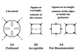
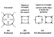
- They must be on the boundary of the sample (or as close to it as possible).
- They must be infinitely small. Practically, they must be as small as possible; any errors given by their non-zero size will be of the order
 , where D is the average diameter of the contact and L is the distance between the contacts.
In addition to this, any leads from the contacts should be constructed from the same batch of wire to minimise thermoelectric effects. For the same reason, all four contacts should be of the same material.
Measurement definitions
- The contacts are numbered from 1 to 4 in a counter-clockwise order, beginning at the top-left contact.
- The current I12 is a positive DC current injected into contact 1 and taken out of contact 2, and is measured in ampereAmpereThe ampere , often shortened to amp, is the SI unit of electric current and is one of the seven SI base units. It is named after André-Marie Ampère , French mathematician and physicist, considered the father of electrodynamics...
s (A). - The voltage V34 is a DC voltage measured between contacts 3 and 4 with no externally applied magnetic field, measured in voltVoltThe volt is the SI derived unit for electric potential, electric potential difference, and electromotive force. The volt is named in honor of the Italian physicist Alessandro Volta , who invented the voltaic pile, possibly the first chemical battery.- Definition :A single volt is defined as the...
s (V). - The sheet resistance RS is measured in ohms (Ω).
Basic measurements
To make a measurement, a current is caused to flow along one edge of the sample (for instance, I12) and the voltage across the opposite edge (in this case, V34) is measured. From these two values, a resistance (for this example,) can be found using Ohm's lawOhm's law
Ohm's law states that the current through a conductor between two points is directly proportional to the potential difference across the two points...
:
In his paper, van der Pauw showed that the sheet resistance of samples with arbitrary shapes can be determined from two of these resistances - one measured along a vertical edge, such as
, and a corresponding one measured along a horizontal edge, such as . The actual sheet resistance is related to these resistances by the van der Pauw formulaReciprocal measurements
The reciprocityReciprocity (electromagnetism)
In classical electromagnetism, reciprocity refers to a variety of related theorems involving the interchange of time-harmonic electric current densities and the resulting electromagnetic fields in Maxwell's equations for time-invariant linear media under certain constraints...
theorem http://www.du.edu/~jcalvert/tech/reciproc.htm tells us that
Therefore, it is possible to obtain a more precise value for the resistances
and by making two additional measurements of their reciprocal values and and averaging the results.We define
and
Then, the van der Pauw formula becomes
Reversed polarity measurements
A further improvement in the accuracy of the resistance values can be obtained by repeating the resistance measurements after switching polarities of both the current source and the voltage meter. Since this is still measuring the same portion of the sample, just in the opposite direction, the values of Rvertical and Rhorizontal can still be calculated as the averages of the standard and reversed polarity measurements. The benefit of doing this is that any offset voltages, such as thermoelectric potentials due to the Seebeck effect, will be cancelled out.Combining these methods with the reciprocal measurements from above leads to the formulas for the resistances being
and
The van der Pauw formula takes the same form as in the previous section.
Measurement accuracy
Both of the above procedures check the repeatability of the measurements. If any of the reversed polarity measurements don't agree to a sufficient degree of accuracy (usually within 3%) with the corresponding standard polarity measurement, then there is probably a source of error somewhere in the setup, which should be investigated before continuing. The same principle applies to the reciprocal measurements—they should agree to a sufficient degree before they are used in any calculations.Calculating sheet resistance
In general, the van der Pauw formula cannot be rearranged to give the sheet resistance RS in terms of known functions. The most notable exception to this is when Rvertical = R = Rhorizontal; in this scenario the sheet resistance is given byIn most other scenarios, an iterative method
Iterative method
In computational mathematics, an iterative method is a mathematical procedure that generates a sequence of improving approximate solutions for a class of problems. A specific implementation of an iterative method, including the termination criteria, is an algorithm of the iterative method...
is used to solve the van der Pauw formula numerically for RS. Unfortunately, the formula doesn't fulfill the preconditions for the Banach fixed point theorem
Banach fixed point theorem
In mathematics, the Banach fixed-point theorem is an important tool in the theory of metric spaces; it guarantees the existence and uniqueness of fixed points of certain self-maps of metric spaces, and provides a constructive method to find those fixed points...
, thus methods based on it don't work. Instead, nested intervals
Nested intervals
In mathematics, a sequence of nested intervals is understood as a collection of sets of real numberssuch that each set In is an interval of the real line, for n = 1, 2, 3, ... , and that furtherfor all n...
converge slowly but steadily.
Background
When a charged particle—such as an electron—is placed in a magnetic fieldMagnetic field
A magnetic field is a mathematical description of the magnetic influence of electric currents and magnetic materials. The magnetic field at any given point is specified by both a direction and a magnitude ; as such it is a vector field.Technically, a magnetic field is a pseudo vector;...
, it experiences a Lorentz force
Lorentz force
In physics, the Lorentz force is the force on a point charge due to electromagnetic fields. It is given by the following equation in terms of the electric and magnetic fields:...
proportional to the strength of the field and the velocity at which it is traveling through it. This force is strongest when the direction of motion is perpendicular to the direction of the magnetic field; in this case the force
where
is the charge on the particle in coulombs, the velocity it is traveling at (centimeters per secondSecond
The second is a unit of measurement of time, and is the International System of Units base unit of time. It may be measured using a clock....
), and
the strength of the magnetic field (WbWeber (unit)
In physics, the weber is the SI unit of magnetic flux. A flux density of one Wb/m2 is one tesla.The weber is named for the German physicist Wilhelm Eduard Weber .- Definition :...
/cm²). Note that centimeters are often used to measure length in the semiconductor industry, which is why they are used here instead of the SI units
International System of Units
The International System of Units is the modern form of the metric system and is generally a system of units of measurement devised around seven base units and the convenience of the number ten. The older metric system included several groups of units...
of meters.
where
is the electron density, is the cross-sectional area of the material and the elementary chargeElementary charge
The elementary charge, usually denoted as e, is the electric charge carried by a single proton, or equivalently, the absolute value of the electric charge carried by a single electron. This elementary charge is a fundamental physical constant. To avoid confusion over its sign, e is sometimes called...
(1.602×10⁻¹⁹ coulombs).
If an external magnetic field is then applied perpendicular to the direction of current flow, then the resulting Lorentz force will cause the electrons to accumulate at one edge of the sample (see part (c) of the figure). Combining the above two equations, and noting that
is the charge on an electron, results in a formula for the Lorentz force experienced by the electrons:This accumulation will create an electric field
Electric field
In physics, an electric field surrounds electrically charged particles and time-varying magnetic fields. The electric field depicts the force exerted on other electrically charged objects by the electrically charged particle the field is surrounding...
across the material due to the uneven distribution of charge, as shown in part (d) of the figure. This in turn leads to a potential difference across the material, known as the Hall voltage
. The current, however, continues to only flow along the material, which indicates that the force on the electrons due to the electric field balances the Lorentz force. Since the force on an electron from an electric field is , we can say that the strength of the electric field is thereforeFinally, the magnitude of the Hall voltage is simply the strength of the electric field multiplied by the width of the material; that is,
where
is the depth of the material. Since the sheet density is defined as the density of electrons multiplied by the depth of the material, we can define the Hall voltage in terms of the sheet density:Making the measurements
Two sets of measurements need to be made: one with a magnetic field in the positive z-direction as shown above, and one with it in the negative z-direction. From here on in, the voltages recorded with a positive field will have a subscript P (for example, V13, P) and those recorded with a negative field will have a subscript N (such as V13, N). For all of the measurements, the magnitude of the injected current should be kept the same; the magnitude of the magnetic field needs to be the same in both directions also.First of all with a positive magnetic field, the current I24 is applied to the sample and the voltage V13, P is recorded; note that the voltages can be positive or negative. This is then repeated for I13 and V42, P.
As before, we can take advantage of the reciprocity theorem to provide a check on the accuracy of these measurements. If we reverse the direction of the currents (i.e. apply the current I42 and measure V31, P, and repeat for I31 and V24, P), then V13, P should be the same as V31, P to within a suitably small degree of error. Similarly, V42, P and V24, P should agree.
Having completed the measurements, a negative magnetic field is applied in place of the positive one, and the above procedure is repeated to obtain the voltage measurements V13, N, V42, N, V31, N and V24, N.
Calculations
First of all, the difference of the voltages for positive and negative magnetic fields needs to be worked out:V13 = V13, P − V13, N
V24 = V24, P − V24, N
V31 = V31, P − V31, N
V42 = V42, P − V42, N
The overall Hall voltage is then
.The polarity of this Hall voltage indicates the type of material the sample is made of; if it is positive, the material is P-type, and if it is negative, the material is N-type.
The formula given in the background can then be rearranged to show that the sheet density
Note that the strength of the magnetic field B needs to be in units of Wb/cm². For instance, if the strength is given in the commonly used units of teslas
Tesla (unit)
The tesla is the SI derived unit of magnetic field B . One tesla is equal to one weber per square meter, and it was defined in 1960 in honour of the inventor, physicist, and electrical engineer Nikola Tesla...
, it can be converted by multiplying it by 10−4.
Mobility
The resistivity of a semiconductor material can be shown to bewhere n and p are the concentration of electrons and holes in the material respectively, and μn and μp are the mobility of the electrons and holes respectively.
Generally, the material is sufficiently doped so that there is many orders-of-magnitude difference between the two concentrations, and so this equation can be simplified to
where nm and μm are the doping level and mobility of the majority carrier respectively.
If we then note that the sheet resistance RS is the resistivity divided by the thickness of the sample, and that the sheet density nS is the doping level multiplied by the thickness, we can divide the equation through by the thickness to get
This can then be rearranged to give the majority carrier mobility in terms of the previously calculated sheet resistance and sheet density: