

Speckle pattern
Encyclopedia
Intensity (physics)
In physics, intensity is a measure of the energy flux, averaged over the period of the wave. The word "intensity" here is not synonymous with "strength", "amplitude", or "level", as it sometimes is in colloquial speech...
pattern produced by the mutual interference of a set of wavefront
Wavefront
In physics, a wavefront is the locus of points having the same phase. Since infrared, optical, x-ray and gamma-ray frequencies are so high, the temporal component of electromagnetic waves is usually ignored at these wavelengths, and it is only the phase of the spatial oscillation that is described...
s. This phenomenon has been investigated by scientists since the time of Newton
Isaac Newton
Sir Isaac Newton PRS was an English physicist, mathematician, astronomer, natural philosopher, alchemist, and theologian, who has been "considered by many to be the greatest and most influential scientist who ever lived."...
, but speckles have come into prominence since the invention of the laser and have now found a variety of applications.
Occurrence
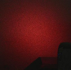
A familiar example is the random pattern created when a laserLaser
A laser is a device that emits light through a process of optical amplification based on the stimulated emission of photons. The term "laser" originated as an acronym for Light Amplification by Stimulated Emission of Radiation...
beam is scattered off a rough surface - see picture. A less familiar example of speckle is the highly magnified image of a star
Star
A star is a massive, luminous sphere of plasma held together by gravity. At the end of its lifetime, a star can also contain a proportion of degenerate matter. The nearest star to Earth is the Sun, which is the source of most of the energy on Earth...
through imperfect optics or through the atmosphere
Atmosphere
An atmosphere is a layer of gases that may surround a material body of sufficient mass, and that is held in place by the gravity of the body. An atmosphere may be retained for a longer duration, if the gravity is high and the atmosphere's temperature is low...
(see speckle imaging
Speckle imaging
Speckle imaging describes a range of high-resolution astronomical imaging techniques based either on the shift-and-add method or on speckle interferometry methods...
). A speckle pattern can also be seen when sunlight is scattered by a fingernail.
The speckle effect is observed when radio wave
Radio Wave
Radio Wave may refer to:*Radio frequency*Radio Wave 96.5, a radio station in Blackpool, UK...
s are scattered from rough surfaces such as ground or sea, and can also be found in ultrasonic imaging. In the output of a multi-mode optical fiber
Multi-mode optical fiber
Multi-mode optical fiber is a type of optical fiber mostly used for communication over short distances, such as within a building or on a campus...
, a speckle pattern results from a superposition of mode
Transverse mode
A transverse mode of a beam of electromagnetic radiation is a particular electromagnetic field pattern of radiation measured in a plane perpendicular to the propagation direction of the beam...
field patterns. If the relative modal group velocities
Group velocity
The group velocity of a wave is the velocity with which the overall shape of the wave's amplitudes — known as the modulation or envelope of the wave — propagates through space....
change with time
Time
Time is a part of the measuring system used to sequence events, to compare the durations of events and the intervals between them, and to quantify rates of change such as the motions of objects....
, the speckle pattern will also change with time. If differential mode attenuation occurs, modal noise results.
Explanation
The speckle effect is a result of the interference of many waves of the same frequency, having different phases and amplitudes, which add together to give a resultant wave whose amplitude, and therefore intensity, varies randomly. If each wave is modelled by a vector, then it can be seen that if a number of vectors with random angles are added together, the length of the resulting vector can be anything from zero to the sum of the individual vector lengths—a 2-dimensional random walkRandom walk
A random walk, sometimes denoted RW, is a mathematical formalisation of a trajectory that consists of taking successive random steps. For example, the path traced by a molecule as it travels in a liquid or a gas, the search path of a foraging animal, the price of a fluctuating stock and the...
, sometimes known as a drunkard's walk.
When a surface is illuminated by a light wave, according to diffraction
Diffraction
Diffraction refers to various phenomena which occur when a wave encounters an obstacle. Italian scientist Francesco Maria Grimaldi coined the word "diffraction" and was the first to record accurate observations of the phenomenon in 1665...
theory, each point on an illuminated surface acts as a source of secondary spherical waves. The light at any point in the scattered light field is made up of waves which have been scattered from each point on the illuminated surface. If the surface is rough enough to create path-length differences exceeding one wavelength
Wavelength
In physics, the wavelength of a sinusoidal wave is the spatial period of the wave—the distance over which the wave's shape repeats.It is usually determined by considering the distance between consecutive corresponding points of the same phase, such as crests, troughs, or zero crossings, and is a...
, giving rise to phase changes greater than 2π, the amplitude, and hence the intensity, of the resultant light varies randomly.
An analogy with water waves may help to understand the speckle phenomenon. Imagine a very large, totally still rectangular pool of water. First consider what happens when someone vibrates a stick at one end of the pool at a constant frequency and amplitude; a circular wavefront is propagated along the surface of the pool. Assume that the pool is large enough that we don't need to consider reflections from the sides or the ends. Now consider what happens if a large number of people, all located at random positions at the end of the pool, vibrate sticks at the same frequency, but varying amplitudes and phases. Each vibrator produces a circular wavefront. At any point along the pool, the movement of the surface is the sum of the individual waves, and is a vibration at the same frequency as the source vibrators. The amplitude and phase of the surface wave at any given point are fixed, but both vary randomly across the surface. At first sight, it will appear that the disturbance in the pool is totally random, but on a closer look, it will be seen that a repeating pattern occurs over one cycle of the vibrating frequency. The average energy of the vibration (which is proportional to the square of the maximum amplitude) at any point, is constant over time, but varies randomly across the surface of the pool. When we observe an illuminated surface, we detect the average energy of the light at the surface; thus the brightness of a given point on a surface which has been illuminated by a set of random scatterers with a single frequency, is constant over time, but varies randomly from point to point, i.e. it is a speckle pattern.
If light of low coherence (i.e. made up of many wavelengths) is used, a speckle pattern will not normally be observed, because the speckle patterns produced by individual wavelengths have different dimensions and will normally average one another out. However, speckle patterns can be observed in polychromatic light in some conditions.
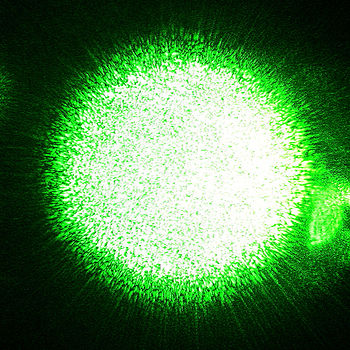
Subjective speckles
When an image is formed of a rough surface which is illuminated by a coherent light (e.g. a laser beam), a speckle pattern is observed in the image plane; this is called a “subjective speckle pattern” - see image above. It is called "subjective" because the detailed structure of the speckle pattern depends on the viewing system parameters; for instance, if the size of the lens aperture changes, the size of the speckles change. If the position of the imaging system is altered, the pattern will gradually change and will eventually be unrelated to the original speckle pattern.This can be explained as follows. Each point in the image can be considered to be illuminated by a finite area in the object. The size of this area is determined by the diffraction-limited resolution of the lens which is given by the Airy disk whose diameter is 2.4λu/D where u is distance between the object and the lens, and D is the diameter of the lens aperture. (This is a simplified model of diffraction-limited imaging).
The light at neighbouring points in the image has been scattered from areas which have many points in common and the intensity of two such points will not differ much. However, two points in the image which are illuminated by areas in the object which are separated by the diameter of the Airy disk, have light intensities which are unrelated. This corresponds to a distance in the image of 2.4λv/D where v is the distance between the lens and the image. Thus, the ‘size’ of the speckles in the image is of this order.
The change in speckle size with lens aperture can be observed by looking at a laser spot on a wall directly, and then through a very small hole. The speckles will be seen to increase significantly in size.
Objective speckles
The light at a given point in the speckle pattern is made up of contributions from the whole of the scattering surface. The relative phases of these waves vary across the surface, so that the sum of the individual waves varies randomly. The pattern is the same regardless of how it is imaged, just as if it were a painted pattern.
The "size" of the speckles is a function of the wavelength of the light, the size of the laser beam which illuminates the first surface, and the distance between this surface and the surface where the speckle pattern is formed. This is the case because when the angle of scattering changes such that the relative path difference between light scattered from the centre of the illuminated area compared with light scattered from the edge of the illuminated changes by λ, the intensity becomes uncorrelated. Dainty derives an expression for the mean speckle size as λz/L where L is the width of the illuminated area and z is the distance between the object and the location of the speckle pattern.
Near-field speckles
Objective speckles are usually obtained in the far field (also called Fraunhofer region, thatis the zone where Fraunhofer diffraction
Fraunhofer diffraction
In optics, the Fraunhofer diffraction equation is used to model the diffraction of waves when the diffraction pattern is viewed at a long distance from the diffracting object, and also when it is viewed at the focal plane of an imaging lens....
happens). This means that they are generated "far" from
the object that emits or scatters light. Speckles can be observed also close to the
scattering object, in the near field (also called Fresnel region, that is, the region where Fresnel diffraction
Fresnel diffraction
In optics, the Fresnel diffraction equation for near-field diffraction, is an approximation of Kirchhoff-Fresnel diffraction that can be applied to the propagation of waves in the near field....
happens). This kind of speckles are called Near Field Speckles.
See near and far field
Near and far field
The near field and far field and the transition zone are regions of the electromagnetic radiation field that emanates from a transmitting antenna, or as a result of radiation scattering off an object...
for a more rigorous definition of "near" and "far".
The statistical properties of a far-field speckle pattern (i.e., the speckle form and dimension)
depend on the form and dimension of the region hit by laser light.
By contrast, a very interesting feature of near field speckles is that
their statistical properties are closely related to the form and structure of the scattering object:
objects that scatter at high angles generate small near field speckles, and vice versa.
Under Rayleigh-Gans condition, in particular, speckle dimension mirrors the average dimension
of the scattering objects, while, in general, the statistical properties of near field
speckles generated by a sample
depend on the light scattering distribution.
Actually, the condition under which the near field speckles appear has been
described as more strict than the usual Fresnel condition.
Applications
When lasers were first invented, the speckle effect was considered to be a severe drawback in using lasers to illuminate objects, particularly in holographic imaging because of the grainy image produced. It was later realized that speckle patterns could carry information about the object's surface deformations, and this effect is exploited in holographic interferometryHolographic interferometry
Holographic interferometry is a technique which enables static and dynamic displacements of objects with optically rough surfaces to be measured to optical interferometric precision . These measurements can be applied to stress, strain and vibration analysis, as well as to non-destructive testing...
and electronic speckle pattern interferometry
Electronic speckle pattern interferometry
Electronic Speckle Pattern Interferometry , also known as TV Holography, is a technique which uses laser light, together with video detection, recording and processing to visualise static and dynamic displacements of components with optically rough surfaces...
. The speckle effect is also used in stellar speckle astronomy, speckle imaging
Speckle imaging
Speckle imaging describes a range of high-resolution astronomical imaging techniques based either on the shift-and-add method or on speckle interferometry methods...
and in eye testing using speckle
Eye testing using speckle
Laser speckle can be employed as a method for conducting a very sensitive eye test.When a surface is illuminated by a laser beam and is viewed by an observer, a speckle pattern is formed on the retina...
.
Speckle is the chief limitation of coherent imaging in optical heterodyne detection
Optical heterodyne detection
Optical heterodyne detection is an important special case of heterodyne detection. In heterodyne detection, a signal of interest at some frequency is non-linearly mixed with a reference "local oscillator" that is set at a close-by frequency...
.
In the case of near field speckles, the statistical properties depend on the light scattering
distribution of a given sample. This allows the use of near field speckle analysis to detect the scattering distribution; this is the so-called near-field scattering
technique.
When the speckle pattern changes in time, due to changes in the illuminated surface, the phenomenon is known as dynamic speckle
Dynamic speckle
In physics, dynamic speckle is a result of the temporal evolution of a speckle pattern where variations in the scattering elements responsible for the formation of the interference pattern in the static situation produce the changes that are seen in the speckle pattern, where its grains change...
, and it can be used to measure activity. In biological materials, the phenomenon is known as biospeckle.
Reduction
Speckle is considered to be a problem in laser based display systems like the Laser TV. Speckle is usually quantified by the speckle contrast. Speckle contrast reduction is essentially the creation of many independent speckle patterns, so that they average out on the retina/detector. This can be achieved by,- Angle diversity: Illumination from different angles.
- Polarization diversity: Use of different polarization states.
- Wavelength diversity: Use of laser sources which differs in wavelength by a small amount.
Rotating diffusers which destroys the spatial coherence of the laser light can also be used to reduce the speckle. Moving/vibrating screens may also be solutions. The Mitsubishi Laser TV
Laser TV
Laser color television , or Laser color video display utilizes two or more individually modulated optical rays of different colors to produce a combined spot that is scanned and projected across the image plane by a polygon-mirror system or less effectively by optoelectronic means to produce a...
appears to use such a screen which requires special care according to their product manual. A more detailed discussion on laser speckle reduction can be found in
Synthetic array heterodyne detection was developed to reduce speckle noise in coherent optical imaging and coherent DIAL LIDAR
LIDAR
LIDAR is an optical remote sensing technology that can measure the distance to, or other properties of a target by illuminating the target with light, often using pulses from a laser...
.
See also
- Dynamic speckleDynamic speckleIn physics, dynamic speckle is a result of the temporal evolution of a speckle pattern where variations in the scattering elements responsible for the formation of the interference pattern in the static situation produce the changes that are seen in the speckle pattern, where its grains change...
- Speckle noiseSpeckle noiseSpeckle noise is a granular noise that inherently exists in and degrades the quality of the active radar and synthetic aperture radar images....
- Optical heterodyne detectionOptical heterodyne detectionOptical heterodyne detection is an important special case of heterodyne detection. In heterodyne detection, a signal of interest at some frequency is non-linearly mixed with a reference "local oscillator" that is set at a close-by frequency...
- Diffusing-wave spectroscopyDiffusing-wave spectroscopyDiffusing-wave spectroscopy is an optical technique derived from dynamic light scattering that studies the dynamics of scattered light in the limit of strong multiple scattering. It has been widely used in the past to study colloidal suspensions, emulsions, foams, gels, biological media and other...