

Electronic speckle pattern interferometry
Encyclopedia
ESPI can be used for stress
Stress (physics)
In continuum mechanics, stress is a measure of the internal forces acting within a deformable body. Quantitatively, it is a measure of the average force per unit area of a surface within the body on which internal forces act. These internal forces are a reaction to external forces applied on the body...
and strain
Strain (materials science)
In continuum mechanics, the infinitesimal strain theory, sometimes called small deformation theory, small displacement theory, or small displacement-gradient theory, deals with infinitesimal deformations of a continuum body...
measurement, vibration
Vibration
Vibration refers to mechanical oscillations about an equilibrium point. The oscillations may be periodic such as the motion of a pendulum or random such as the movement of a tire on a gravel road.Vibration is occasionally "desirable"...
mode analysis and nondestructive testing
Nondestructive testing
Nondestructive testing or Non-destructive testing is a wide group of analysis techniques used in science and industry to evaluate the properties of a material, component or system without causing damage....
.
ESPI is similar to holographic interferometry
Holographic interferometry
Holographic interferometry is a technique which enables static and dynamic displacements of objects with optically rough surfaces to be measured to optical interferometric precision . These measurements can be applied to stress, strain and vibration analysis, as well as to non-destructive testing...
in many ways, but there are also significant differences between the two techniques.
How ESPI works
The component under investigation must have an optically rough surface so that when it is illuminated by an expanded laser beam, the image formed is a subjective speckle patternSpeckle pattern
A speckle pattern is a random intensity pattern produced by the mutual interference of a set of wavefronts. This phenomenon has been investigated by scientists since the time of Newton, but speckles have come into prominence since the invention of the laser and have now found a variety of...
. The light arriving at a point in the speckled image is scattered from a finite area of the object, and its phase
Phase (waves)
Phase in waves is the fraction of a wave cycle which has elapsed relative to an arbitrary point.-Formula:The phase of an oscillation or wave refers to a sinusoidal function such as the following:...
, amplitude
Amplitude
Amplitude is the magnitude of change in the oscillating variable with each oscillation within an oscillating system. For example, sound waves in air are oscillations in atmospheric pressure and their amplitudes are proportional to the change in pressure during one oscillation...
and intensity
Intensity (physics)
In physics, intensity is a measure of the energy flux, averaged over the period of the wave. The word "intensity" here is not synonymous with "strength", "amplitude", or "level", as it sometimes is in colloquial speech...
, which are all random, are directly related to the microstructure of that area in the object.
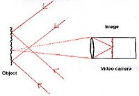
A second light field, known as the reference beam, is derived from the same laser beam and is superimposed on the video camera image (different configurations enable different measurements to be made). The two light fields interfere and the resulting light field has random amplitude, phase and intensity, and is therefore also a speckle pattern. If the object is displaced or deformed, the distance between object and image will change, and hence the phase of the image speckle pattern will change. The relative phases of reference and object beam change, and therefore the intensities of the combined light field changes. However, if the phase change of the object light field is a multiple of 2π, the relative phases of the two light fields will be unchanged, and the intensity of the overall image will also be unchanged.
To visualise this effect, the image and reference beams are combined on a video camera and recorded. When the object has been displaced/deformed, the new image is subtracted point by point from the first image. The resulting image is a speckle pattern with black 'fringes' representing contours of constant 2nπ.
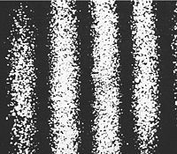
Out-of-plane displacement measurement
The reference beam is an expanded beam derived from the laser beam, and is added to the image of the object which is formed on the video camera.The amplitude of the light at any point in the image is the sum of the light from the object (object beam) and the second beam (reference beam). If the object moves in the direction of viewing, the distance travelled by the object beam changes, its phase changes, and therefore the amplitude of the combined beams changes. When the second speckle pattern is subtracted from the first, fringes are obtained which represent contours of displacement along the viewing direction (out-of-plane displacement). These are not interference fringes, and are sometimes referred to as 'correlation' fringes since they map out areas of the speckle pattern which are more or less correlated. Strictly speaking, the fringes represent purely out-of-plane displacement only if the surface is illuminated normally (this requires a beam splitter to be used to illuminate the object), but the dependence on in-plane movement is relatively small unless the object illumination is well away from the normal direction.
The fringes in the image above are out-of-plane fringes. The plate has been rotated about a vertical axis and the fringes represent contours of constant displacement. The contour interval is about 0.3μm since a He-Ne laser was used in the system. As with many interferometric techniques, it is not possible to identify the zero-order fringe without additional information from the system.
Holographic interferometry
Holographic interferometry
Holographic interferometry is a technique which enables static and dynamic displacements of objects with optically rough surfaces to be measured to optical interferometric precision . These measurements can be applied to stress, strain and vibration analysis, as well as to non-destructive testing...
provides the same information as out-of-plane ESPI fringes.
Out-of-plane vibration measurement
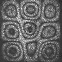
This system is simpler to operate than either of the displacement measuring systems, as the fringes are obtained without any recording being required. The vibration mode can be observed in the image from the camera as a variation in speckle contrast rather than as a variation in intensity but it quite difficult to discern. When the image is high-pass filtered, the variation in contrast is converted to a variation in intensity, and a fringe pattern of the form shown in the diagram is observed where the fringes are clearly visible.
Holographic interferometry
Holographic interferometry
Holographic interferometry is a technique which enables static and dynamic displacements of objects with optically rough surfaces to be measured to optical interferometric precision . These measurements can be applied to stress, strain and vibration analysis, as well as to non-destructive testing...
can be used in the same way to map out vibration modes.
In-plane measurement
The object is illuminated by two beams derived from the same laser beam which are incident on the object from opposite sides. When the object is displaced or deformed in the direction normal to the viewing direction (i.e in it its own plane), the phase of one beam increases, while that of the other decreases, so that the relative phase of the two beams changes. When this change is a multiple of 2π, the speckle pattern remains the same, while elsewhere it changes. When the subtraction technique described above is used, fringes are obtained which represent in-plane displacement contours.In-plane displacement gradient measurement
The object is illuminated by two beams derived from the same laser which are incident on the object from the same side but at different angles. When the object is displaced or deformed in its own plane, it can be shown that the relative phases of the two beams changes in proportion to the gradient of the in-plane displacement. Again, subtraction of the two images is used to display the fringes.Holographic interferometry
Holographic interferometry
Holographic interferometry is a technique which enables static and dynamic displacements of objects with optically rough surfaces to be measured to optical interferometric precision . These measurements can be applied to stress, strain and vibration analysis, as well as to non-destructive testing...
has no equivalent to in-plane measuring ESPI.