
Ship Gun Fire Control Systems
Encyclopedia
Ship gun fire-control system
Fire-control system
A fire-control system is a number of components working together, usually a gun data computer, a director, and radar, which is designed to assist a weapon system in hitting its target. It performs the same task as a human gunner firing a weapon, but attempts to do so faster and more...
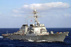
s (GFCS) enable remote and automatic targeting of guns against ships, aircraft, and shore targets, with or without the aid of radar or optical sighting. Most US ships destroyers or larger (but not destroyer escorts or escort carriers) employed GFCS for 5 inch and larger guns, up to battleships such as the USS Iowa
Armament of the Iowa class battleship
The armament of the s underwent a massive evolution since the first Iowa-class ship was laid down in June 1940. Owing to the continual evolution of the weaponry aboard these battleships they remain the most heavily armed gunships the United States has ever put to sea.In their World War II...
. After the 1950s, GFCSs were integrated with missile fire-control system
Fire-control system
A fire-control system is a number of components working together, usually a gun data computer, a director, and radar, which is designed to assist a weapon system in hitting its target. It performs the same task as a human gunner firing a weapon, but attempts to do so faster and more...
s and other ship sensors.
The major components of a GFCS are a manned director
Director (military)
A director, also called an auxiliary predictor, is a mechanical or electronic computer that continuously calculates trigonometric firing solutions for use against a moving target, and transmits targeting data to direct the weapon firing crew....
, with or replaced by radar or television camera, a computer, stabilizing device or gyro, and equipment in a plotting room
For the US, the brains were first provided by the Mark 1A Fire Control Computer
Mark I Fire Control Computer
The Mark 1, and later the Mark 1A, Fire Control Computer was a component of the Mark 37 Gun Fire Control System deployed by the United States Navy during World War II and up to 1969. It was used on a variety of ships, ranging from destroyers to battleships . The Mark 37 system used tachymetric...
which was an electro-mechanical analog ballistic computer that provided accurate firing solutions which could automatically control one or more gun mounts against stationary, or moving targets on the surface or in the air. This gave American forces a technological advantage in World War II against the Japanese who did not develop this technology, and still used visual correction of shots with colored splashes. Digital computers would not be adopted for this purpose by the US until the mid 1970s. However, it must be emphasized that all analogue AA fire control systems had severe limitations, and even the USN Mk 37 required nearly 1000 rounds of 5" mechanical fuze ammunition per kill, even in late 1944.
The MK 37 was the first of a series of evolutionary improvements in gun fire control systems.
History
Naval fire control is more complex than for single ground-based gun because of the need to control the firing of several guns at once. In naval engagements both the firing guns and target are moving, and the variables are compounded by the greater distances and times involved.Furthermore, a ship rolls and pitches, making gyroscopic stabilization extremely desirable. Naval gun fire control potentially involves three levels of complexity:
- Local control originated with primitive gun installations aimed by the individual gun crews.
- The director system of fire control was pioneered by British Royal NavyRoyal NavyThe Royal Navy is the naval warfare service branch of the British Armed Forces. Founded in the 16th century, it is the oldest service branch and is known as the Senior Service...
in 1912. All guns on a single ship were laid from a central position placed above the bridge as high as possible. The director became a design feature of battleships, with Japanese pagodaPagodaA pagoda is the general term in the English language for a tiered tower with multiple eaves common in Nepal, India, China, Japan, Korea, Vietnam and other parts of Asia. Some pagodas are used as Taoist houses of worship. Most pagodas were built to have a religious function, most commonly Buddhist,...
-style masts designed to maximize the view of the director over long ranges. A fire control officer who ranged the salvos transmitted elevations and angles to individual guns. - Coordinated gunfire from a formation of ships at a single target was a focus of battleship fleet operations. An officer on the flagship would signal target information to other ships in the formation.
Corrections can be made for surface wind velocity, firing ship roll and pitch, powder magazine temperature, drift of rifled projectiles, individual gun bore diameter adjusted for shot-to-shot enlargement, and rate of change of range with additional modifications to the firing solution based upon the observation of preceding shots. More sophisticated fire control systems consider more of these factors rather than relying on simple correction of observed fall of shot. Differently colored dye markers were sometimes included with large shells so individual guns, or individual ships in formation, could distinguish their shell splashes during daylight.
Rudimentary naval fire control systems were first developed around the time of World War I
World War I
World War I , which was predominantly called the World War or the Great War from its occurrence until 1939, and the First World War or World War I thereafter, was a major war centred in Europe that began on 28 July 1914 and lasted until 11 November 1918...
. Local control had been used up until that time, and remained in use on smaller warships and auxiliaries through World War II
World War II
World War II, or the Second World War , was a global conflict lasting from 1939 to 1945, involving most of the world's nations—including all of the great powers—eventually forming two opposing military alliances: the Allies and the Axis...
. It may still be used for machineguns aboard patrol craft.
For the UK, their first system was built before the Great War. At the heart was an analogue computer designed by Commander (later Admiral Sir) Frederic Charles Dreyer
Frederic Charles Dreyer
Admiral Sir Frederic Charles Dreyer, GBE, KCB was an officer of the Royal Navy who developed a fire control system for British warships...
that calculated rate of change of range. The Dreyer Table was to be improved and served into the interwar period at which point it was superseded in new and reconstructed ships by the Admiralty Fire Control Table
Admiralty Fire Control Table
thumb|Admiralty Fire Control Table in the transmitting station of [[HMS Belfast |HMS Belfast]].The Admiralty Fire Control Table was an electromechanical analogue computer fire-control system that calculated the correct elevation and deflection of a Royal Navy cruiser or battleships' main armament,...
.
The use of Director controlled firing together with the fire control computer moved the control of the gun laying from the individual turrets to a central position, although individual gun mounts and multi-gun turrets may retain a local control option for use when battle damage limits Director information transfer. Guns could then be fired in planned salvos, with each gun giving a slightly different trajectory. Dispersion of shot caused by differences in individual guns, individual projectiles, powder ignition sequences, and transient distortion of ship structure was undesirably large at typical naval engagement ranges. Directors high on the superstructure had a better view of the enemy than a turret mounted sight, and the crew operating it were distant from the sound and shock of the guns.
Unmeasured and uncontrollable ballistic factors like high altitude temperature, humidity, barometric pressure, wind direction and velocity required final adjustment through observation of fall of shot. Visual range measurement (of both target and shell splashes) was difficult prior to availability of RADAR. The British favoured coincident rangefinder
Rangefinder
A rangefinder is a device that measures distance from the observer to a target, for the purposes of surveying, determining focus in photography, or accurately aiming a weapon. Some devices use active methods to measure ; others measure distance using trigonometry...
s while the Germans and the U.S. Navy, stereoscopic type. The former were less able to range on an indistinct target but easier on the operator over a long period of use, the latter the reverse.
In a typical World War II British ship the fire control system connected the individual gun turrets to the director tower (where the sighting instruments were) and the analogue computer in the heart of the ship. In the director tower, operators trained their telescopes on the target; one telescope measured elevation and the other bearing. Rangefinder telescopes on a separate mounting measured the distance to the target. These measurements were converted by the Fire Control Table into bearings and elevations for the guns to fire on. In the turrets, the gunlayers adjusted the elevation of their guns to match an indicator which was the elevation transmitted from the Fire Control table - a turret layer did the same for bearing. When the guns were on target they were centrally fired.
During the Battle of Jutland
Battle of Jutland
The Battle of Jutland was a naval battle between the British Royal Navy's Grand Fleet and the Imperial German Navy's High Seas Fleet during the First World War. The battle was fought on 31 May and 1 June 1916 in the North Sea near Jutland, Denmark. It was the largest naval battle and the only...
, while the British were thought by some to have the finest fire control system in the world at that time, only 3% of their shots actually struck their targets. At that time, the British primarily used a manual fire control system. The one British ship in the battle that had a mechanical fire control system turned in the best shooting results. This experience contributed to computing rangekeeper
Rangekeeper
Rangekeepers were electromechanical fire control computers used primarily during the early part of the 20th century. They were sophisticated analog computers whose development reached its zenith following World War II, specifically the Computer Mk 47 in the Mk 68 Gun Fire Control system. During...
s becoming standard issue.
The US Navy's first deployment of a rangekeeper was on the USS Texas
USS Texas (BB-35)
USS Texas , the second ship of the United States Navy named in honor of the U.S. state of Texas, is a . The ship was launched on 18 May 1912 and commissioned on 12 March 1914....
in 1916. Because of the limitations of the technology at that time, the initial rangekeepers were crude. For example, during World War I the rangekeepers would generate the necessary angles automatically but sailors had to manually follow the directions of the rangekeepers. This task was called "pointer following" but the crews tended to make inadvertent errors when they became fatigued during extended battles. During World War II, servomechanisms (called "power drives" in the U.S. Navy) were developed that allowed the guns to automatically steer to the rangekeeper's commands with no manual intervention, though pointers still worked even if automatic control was lost. The Mk. 1 and Mk. 1A computers contained approximately 20 servomechanisms, mostly position servos, to minimize torque load on the computing mechanisms.
During their long service life, rangekeepers were updated often as technology advanced and by World War II they were a critical part of an integrated fire control system. The incorporation of radar into the fire control system early in World War II provided ships with the ability to conduct effective gunfire operations at long range in poor weather and at night.
The Aichi Clock Company first produced the Type 92 Shagekiban Low Angle analog computer in 1932. The USN Rangekeeper and the Mark 38 GFCS had an edge over Imperial Japanese Navy systems in operability and flexibility. The US system allowing the plotting room team to quickly identify target motion changes and apply appropriate corrections. The newer Japanese systems such as the Type 98 Hoiban and Shagekiban on the Yamato-class were more up to date, which eliminated the Sokutekiban, but it still relied on 7 operators. In contrast to US radar aided system, the Japanese relied on averaging optical rangefinders, lacked gyros to sense the horizon, and required manual handling of follow-ups on the Sokutekiban, Shagekiban, Hoiban as well as guns themselves.
This could have played a role in Center Force’s battleships dismal performance in the Battle off Samar
Battle off Samar
The Battle off Samar was the centermost action of the Battle of Leyte Gulf, one of the largest naval battles in history, which took place in the Philippine Sea off Samar Island, in the Philippines on 25 October 1944...
in October 1944. In that action, destroyers pitted against the world's largest armored battleships and cruisers dodged shells to within torpedo firing range, while lobbing hundreds of accurate automatically aimed 5 inch rounds on target. Cruisers did not land hits on splash-chasing escort carriers until after an hour of pursuit to close within 5 miles. Although the Japanese pursued a doctrine of achieving superiority at long gun ranges, one cruiser fell victim to secondary explosions caused by hits from within the range of carrier-based single "peashooter" 5 in guns. Eventually with the aid of hundreds of carrier based aircraft, a battered center force was turned back just before it could have finished off survivors of the lightly armed task force of screening escorts and escort carriers of Taffy 3. The Battle of the Surigao Strait also established the clear superiority of US radar-assisted systems at night.
The rangekeeper's target position prediction characteristics could be used to defeat the rangekeeper. For example, many captains under long range gun attack would make violent maneuvers to "chase salvos." A ship that is chasing salvos is maneuvering to the position of the last salvo splashes. Because the rangekeepers are constantly predicting new positions for the target, it is unlikely that subsequent salvos will strike the position of the previous salvo. Practical rangekeepers had to assume that targets were moving in a straight-line path at a constant speed, to keep complexity to acceptable limits. A sonar rangekeeper was built to include a target circling at a constant radius of turn, but that function had been disabled.
Only the RN and USN achieved 'blindfire' radar fire-control, with no need to visually acquire the opposing vessel. The Axis powers
Axis Powers
The Axis powers , also known as the Axis alliance, Axis nations, Axis countries, or just the Axis, was an alignment of great powers during the mid-20th century that fought World War II against the Allies. It began in 1936 with treaties of friendship between Germany and Italy and between Germany and...
all lacked this capability. Classes such as Iowa and South Dakota could lob shells over visual horizon, in darkness, through smoke or weather. American systems, in common with many contemporary major navies, had Gyroscopic stable vertical elements, so they could keep a solution on a target even during maneuvers. By the start of World War II British, German and American warships could both shoot and maneuver using sophisticated analog fire-control computers that incorporated Gyro compass and Gyro Level inputs. Off Cape Matapan
Battle of Cape Matapan
The Battle of Cape Matapan was a Second World War naval battle fought from 27–29 March 1941. The cape is on the southwest coast of Greece's Peloponnesian peninsula...
the British Mediterranean Fleet using radar ambushed and mauled an Italian fleet, although actual fire was under optical control using starshells. At the Naval Battle of Guadalcanal
Naval Battle of Guadalcanal
The Naval Battle of Guadalcanal, sometimes referred to as the Third and Fourth Battles of Savo Island, the Battle of the Solomons, The Battle of Friday the 13th, or, in Japanese sources, as the , took place from 12–15 November 1942, and was the decisive engagement in a series of naval battles...
the USS Washington
USS Washington
Ten ships of the United States Navy have been named Washington, the first six in honor of George Washington, the seventh in honor of Department of the Treasury official and assistant Postmaster General Peter G...
, undetected in complete darkness, inflicted fatal damage on the battleship Kirishima
Japanese battleship Kirishima
was a warship of the Imperial Japanese Navy during World War I and World War II. Designed by British naval engineer George Thurston, she was the third launched of the four Kongō-class battlecruisers, among the most heavily armed ships in any navy when built...
under radar fire-control alone.
The last combat action for the analog rangekeepers, at least for the US Navy, was in the 1991 Persian Gulf War
Gulf War
The Persian Gulf War , commonly referred to as simply the Gulf War, was a war waged by a U.N.-authorized coalition force from 34 nations led by the United States, against Iraq in response to Iraq's invasion and annexation of Kuwait.The war is also known under other names, such as the First Gulf...
when the rangekeepers on the Iowa-class battleships directed their last rounds in combat.
British Royal Navy systems
- Dreyer Table
- Pollen's Argo ClockArthur PollenArthur Joseph Hungerford Pollen was a writer on naval affairs in the early 1900s who recognised the need for a computer-based fire-control system...
- Admiralty Fire Control TableAdmiralty Fire Control Tablethumb|Admiralty Fire Control Table in the transmitting station of [[HMS Belfast |HMS Belfast]].The Admiralty Fire Control Table was an electromechanical analogue computer fire-control system that calculated the correct elevation and deflection of a Royal Navy cruiser or battleships' main armament,...
- from 1920s - HACSHACSHACS, an acronym of High Angle Control System, was a British anti-aircraft fire-control system employed by the Royal Navy from 1931 onwards and used widely during World War II...
- A/A system from 1931 - Fuze Keeping ClockFuze Keeping ClockThe Fuze Keeping Clock was a simplified version of the Royal Navy's High Angle Control System analogue fire control computer. It first appeared as the FKC Mk1 in destroyers of the 1938 Tribal class, while later variants were used on sloops, frigates, destroyers, aircraft carriers and several...
- simplified HACS A/A system for destroyers from 1938 - Pom-Pom DirectorPom-Pom Director-History:The Vickers 40mm "Pom-Pom" Antiaircraft mounting was introduced to the Royal Navy in the early 1930s. The mounting was capable of a tremendous volume of fire but the crew had great difficulty in aiming the mounting due to the smoke and vibration created by the guns...
- pioneered use of gyroscopic TachymetricTachymetricA tachymetric anti-aircraft fire control system refers to a method of generating target position, speed, direction, and rate of target range change, by computing these parameters directly from measured data....
fire-control for short range weapons - From 1940 - Gyro Rate UnitGyro Rate Unit-History:The Royal Navy, after World War I, became increasingly concerned with the threat posed by aerial attack. In 1930 the RN began equipping ships with the High Angle Control System, a non-tachymetric anti-aircraft fire control system, that would compute the gun laying orders and the time fuze...
- pioneered use of gyroscopic Tachymetric fire-control for medium calibre weapons - From 1940 - Royal Navy Radar - pioneered the use of radar for A/A fire-control and centimetric radar for surface fire-control - from 1939
MK 33 Gun Fire Control System (GFCS)
The Mk 33 GFCS was a power-driven fire control director, less advanced than the MK 37. The Mark 33 GFCS used a Mk 10 RangekeeperRangekeeper
Rangekeepers were electromechanical fire control computers used primarily during the early part of the 20th century. They were sophisticated analog computers whose development reached its zenith following World War II, specifically the Computer Mk 47 in the Mk 68 Gun Fire Control system. During...
, analog fire-control computer. The entire rangekeeper was mounted in an open director rather than in a separate plotting room as in the RN HACS, or the later Mk 37 GFCS, and this made it difficult to upgrade the Mk 33 GFCS. It could compute firing solutions for targets moving at up to 320 knots, or 400 knots in a dive. Its installations started in the late 1930s on destroyers, cruisers and aircraft carriers with two Mk 33 directors mounted fore and aft of the island. They had no fire-control radar initially, and were aimed only by sight. After 1942, some of these directors were enclosed and had a Mk 4 fire-control radar added to the roof of the director, while others had a Mk 4 radar added over the open director. With the Mk 4 large aircraft at up to 40,000 yards could be targeted. It had less range against low-flying aircraft, and large surface ships had to be within 30,000 yards. With radar, targets could be seen and hit accurately at night, and through weather. The Mark 33 and 37 systems used tachymetric
Tachymetric
A tachymetric anti-aircraft fire control system refers to a method of generating target position, speed, direction, and rate of target range change, by computing these parameters directly from measured data....
target motion prediction. The USN never considered the Mk 33 to be a satisfactory system, but wartime production problems, and the added weight and space requirements of the Mk 37 precluded phasing out the Mk 33:
"Although superior to older equipment, the computing mechanisms within the range keeper (Mk10) were too slow, both in reaching initial solutions on first picking up a target and in accommodating frequent changes in solution caused by target maneuvers. The Mk 33 was thus distinctly inadequate, as indicated to some observers in simulated air attack exercises prior to hostilities. However, final recognition of the seriousness of the deficiency and initiation of replacement plans were delayed by the below decks space difficulty, mentioned in connection with the Mk28 replacement. Furthermore, priorities of replacements of older and less effective director systems in the crowded wartime production program were responsible for the fact the Mk 33's service was lengthened to the cessation of hostilities."
MK 37 Gun Fire Control System (GFCS)
"While the defects were not prohibitive and the Mark 33 remained in production until fairly late in World War II, the Bureau started the development of an improved director in 1936, only 2 years after the first installation of a Mark 33. The objective of weight reduction was not met, since the resulting director system actually weighed about 8000 pounds more than the equipment it was slated to replace, but the Gun Director Mark 37 that emerged from the program possessed virtues that more than compensated for its extra weight. Though the gun orders it provided were the same as those of the Mark 33, it supplied them with greater reliability and gave generally improved performance with 5-inch gun batteries, whether they were used for surface or antiaircraft use. Moreover, the stable element and computer, instead of being contained in the director housing were installed below deck where they were less vulnerable to attack and less of a jeopardy to a ship's stability. The design provided for the ultimate addition of radar, which later permitted blind firing with the director. In fact, the Mark 37 system was almost continually improved. By the end of 1945 the equipment had run through 92 modifications—almost twice the total number of directors of that type which were in the fleet on December 7, 1941. Procurement ultimately totalled 841 units, representing an investment of well over $148,000,000. Destroyers, cruisers, battleships, carriers, and many auxiliaries used the directors, with individual installations varying from one aboard destroyers to four on each battleship. The development of the Gun Directors Mark 33 and 37 provided the United States Fleet with good long range fire control against attacking planes. But while that had seemed the most pressing problem at the time the equipments were placed under development, it was but one part of the total problem of air defense. At close-in ranges the accuracy of the directors fell off sharply; even at intermediate ranges they left much to be desired. The weight and size of the equipments militated against rapid movement, making them difficult to shift from one target to another.Their efficiency was thus in inverse proportion to the proximity of danger." The computer was completed as the Ford Mk 1 computer by 1935. Rate information for height changes enabled complete solution for aircraft targets moving over 400 mph. Destroyers starting with the Sims-classSims class destroyer
The Sims-class consisted of 12 destroyers in the United States Navy, built in seven various shipyards, and commissioned in 1939 and 1940. It was the last United States destroyer class completed prior to World War II. All Sims-class ships saw action in World War II, and seven survived the war...
employed one of these computers, battleships up to four. The system's effectiveness against aircraft diminished as planes became faster, but toward the end of World War II
World War II
World War II, or the Second World War , was a global conflict lasting from 1939 to 1945, involving most of the world's nations—including all of the great powers—eventually forming two opposing military alliances: the Allies and the Axis...
upgrades were made to the Mk37 System, and it was made compatible with the development of the VT (Variable Time) proximity fuze
Proximity fuze
A proximity fuze is a fuze that is designed to detonate an explosive device automatically when the distance to target becomes smaller than a predetermined value or when the target passes through a given plane...
which exploded when it was near a target, rather than by timer or altitude, greatly increasing the probability that any one shell would destroy a target.
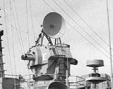
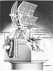
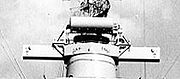
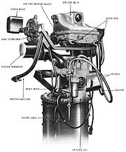
Mark 37 Director
The Director Officer also had a slew sight used to quickly point the director towards a new target. Up to four Mark 37 Gun Fire Control Systems were installed on battleships. On a battleship, the director is protected by 1.5 inches of armor, and weighs 21 tons. The Mark 37 director aboard the is protected with one-half inch of armor plate and weighs 16 tons.
Although the rangefinder had significant mass and inertia, the crosslevel servo normally was only lightly loaded, because the rangefinder's own inertia kept it essentially horizontal; the servo's task was usually simply to ensure that the rangefinder and sight telescopes remained horizontal.
Mk. 37 director train (bearing) and elevation drives were by D.C. motors fed from Amplidyne rotary power-amplifying generators. Although the train Amplidyne was rated at several kilowatts maximum output, its input signal came from a pair of 6L6 audio beam tetrode vacuum tubes (valves, in the U.K.).
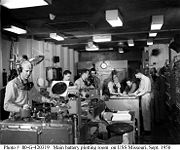
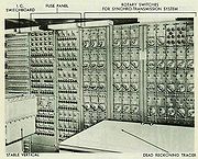
Plotting room
In battleships, the Secondary Battery Plotting Rooms were down below the waterline and inside the armor belt. They contained four complete sets of the fire control equipment needed to aim and shoot at four targets. Each set included a Mark 1A computer, a Mark 6 Stable Element, FC radar controls and displays, parallax correctors, a switchboard, and people to operate it all.(In the early 20th century, successive range and/or bearing readings were probably plotted either by hand or by the fire control devices (or both). Humans were very good data filters, able to plot a useful trend line given somewhat-inconsistent readings. As well, the Mark 8 Rangekeeper included a plotter. The distinctive name for the fire-control equipment room took root, and persisted even when there were no plotters.)
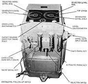
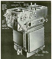
Ford Mark 1A Fire Control Computer
The Mark 1A Fire Control ComputerMark I Fire Control Computer
The Mark 1, and later the Mark 1A, Fire Control Computer was a component of the Mark 37 Gun Fire Control System deployed by the United States Navy during World War II and up to 1969. It was used on a variety of ships, ranging from destroyers to battleships . The Mark 37 system used tachymetric...
was an electro-mechanical analog ballistic computer. Originally designated the Mark 1, design modifications were extensive enough to change it to "Mk. 1A". The Mark 1A appeared post World War II and may have incorporated technology developed for the Bell Labs Mark 8, Fire Control Computer
Mark 8, Fire Control Computer
The Mark 8 Fire Control Computer was developed by Bell Laboratories during World War II. It was initially requested by the USN Bureau of Ordnance as an alternative to the Ford Instruments Mark I Fire Control Computer, in case supplies of the Mk I were interrupted or were unable to be manufactured...
. Sailor
Sailor
A sailor, mariner, or seaman is a person who navigates water-borne vessels or assists in their operation, maintenance, or service. The term can apply to professional mariners, military personnel, and recreational sailors as well as a plethora of other uses...
s would stand around a box 62 inches long, 38 inches wide, and 45 inches high. Even though built with extensive use of an aluminum alloy framework (including thick internal mechanism support plates) and computing mechanisms mostly made of aluminum alloy, it weighed as much as a car, about 3125 lb, with the Star Shell Computer Mark 1 adding another 215 lb. It used 115 volts AC, 60 Hz, single phase, and typically a few amperes or even less. Under worst-case fault conditions, its synchros apparently could draw as much as 140 amperes, or 15,000 watts (about the same as 3 houses while using ovens). Almost all of the computer's inputs and outputs were by synchro torque transmitters and receivers.
Its function was to automatically aim the guns so that a fired projectile would collide with the target. This is the same function as the main battery’s Mk 8 Rangekeeper
Rangekeeper
Rangekeepers were electromechanical fire control computers used primarily during the early part of the 20th century. They were sophisticated analog computers whose development reached its zenith following World War II, specifically the Computer Mk 47 in the Mk 68 Gun Fire Control system. During...
above except that some of the targets the Mark 1A had to deal with also moved in elevation — and much faster. For a surface target, the Secondary Battery’s Fire Control problem is the same as the Main Battery’s with the same type inputs and outputs. The major difference between the two computers is their ballistics calculations. The amount of gun elevation needed to project a 5-in shell nine nautical miles (17 km) is very different from the elevation needed to project a 16-in shell the same distance.
In operation, this computer received target range, bearing, and elevation from the gun director. As long as the director was on target, clutches in the computer were closed, and movement of the gun director (along with changes in range) made the computer converge its internal values of target motion to values matching those of the target. While converging, the computer fed aided-tracking ("generated") range, bearing, and elevation to the gun director. If the target remained on a straight-line course at a constant speed (and in the case of aircraft, constant rate of change of altitude ("rate of climb"), the predictions became accurate and, with further computation, gave correct values for the gun lead angles and fuze setting.
Concisely, the target's movement was a vector, and if that didn't change, the generated range, bearing, and elevation were accurate for up to 30 seconds. Once the target's motion vector became stable, the computer operators told the gun director officer ("Solution Plot!"), who usually gave the command to commence firing. Unfortunately, this process of inferring the target motion vector required a few seconds, typically, which might take too long.
The process of determining the target's motion vector was done primarily with an accurate constant-speed motor, disk-ball-roller integrators, nonlinear cams, mechanical resolvers, and differentials. Four special coordinate converters, each with a mechanism in part like that of a traditional computer mouse, converted the received corrections into target motion vector values. The Mk. 1 computer attempted to do the coordinate conversion (in part) with a rectangular-to polar converter, but that didn't work as well as desired (sometimes trying to make target speed negative!). Part of the design changes that defined the Mk. 1A were a re-thinking of how to best use these special coordinate converters; the coordinate converter ("vector solver") was eliminated.
The Stable Element, which in contemporary terminology would be called a vertical gyro, stabilized the sights in the director, and provided data to compute stabilizing corrections to the gun orders. Gun lead angles meant that gun-stabilizing commands differed from those needed to keep the director's sights stable. Ideal computation of gun stabilizing angles required an impractical number of terms in the mathematical expression, so the computation was approximate.
To compute lead angles and time fuze setting, the target motion vector's components as well as its range and altitude, wind direction and speed, and own ship's motion combined to predict the target's location when the shell reached it. This computation was done primarily with mechanical resolvers ("component solvers"), multipliers, and differentials, but also with one of four three-dimensional cams.
Based on the predictions, the other three of the three-dimensional cams provided data on ballistics of the gun and ammunition that the computer was designed for; it could not be used for a different size or type of gun except by rebuilding that could take weeks.
Servos in the computer boosted torque accurately to minimize loading on the outputs of computing mechanisms, thereby reducing errors, and also positioned the large synchros that transmitted gun orders (bearing and elevation, sight lead angles, and time fuze setting).These were electromechanical "bang-bang", yet had excellent performance.
The anti-aircraft fire control problem was more complicated because it had the additional requirement of tracking the target in elevation and making target predictions in three dimensions. The outputs of the Mk 1A were the same (gun bearing and elevation), except fuze time was added. The fuze time was needed because the ideal of directly hitting the fast moving aircraft with the projectile was impractical. With fuze time set into the shell, it was hoped that it would explode near enough to the target to destroy it with the shock wave and shrapnel. Towards the end of World War II
World War II
World War II, or the Second World War , was a global conflict lasting from 1939 to 1945, involving most of the world's nations—including all of the great powers—eventually forming two opposing military alliances: the Allies and the Axis...
, the invention of the VT proximity fuze
Proximity fuze
A proximity fuze is a fuze that is designed to detonate an explosive device automatically when the distance to target becomes smaller than a predetermined value or when the target passes through a given plane...
eliminated the need to use the fuze time calculation and its possible error. This greatly increased the odds of destroying an air target. Digital fire control computers were not introduced into service until the mid 1970s.
Central aiming from a gun director has a minor complication in that the guns are often far enough away from the director to require parallax correction so they aim correctly. In the Mk. 37 GFCS, the Mk1 / 1A sent parallax data to all gun mounts; each mount had its own scale factor (and "polarity") set inside the train (bearing) power drive (servo) receiver-regulator (controller).
Twice in its history, internal scale factors were changed, presumably by changing gear ratios. Target speed had a hard upper limit, set by a mechanical stop. It was originally 300 knots, and subsequently doubled in each rebuild.
These computers were built by Ford Instrument Company, Long Island City, Queens, New York. The company was named after Hannibal C. Ford, a genius designer, and principal in the company. Special machine tools machined face cam grooves and accurately duplicated 3-D ballistic cams.
Generally speaking, these computers were very well designed and built, very rugged, and almost trouble-free, frequent tests included entering values via the handcranks and reading results on the dials, with the time motor stopped. These were static tests. Dynamic tests were done similarly, but used gentle manual acceleration of the "time line" (integrators) to prevent possible slippage errors when the time motor was switched on; the time motor was switched off before the run was complete, and the computer was allowed to coast down. Easy manual cranking of the time line brought the dynamic test to its desired end point, when dials were read.
As was typical of such computers, flipping a lever on the handcrank's support casting enabled automatic reception of data and disengaged the handcrank gear. Flipped the other way, the gear engaged, and power was cut to the receiver's servo motor.
The mechanisms (including servos) in this computer are described superbly, with many excellent illustrations, in the Navy publication OP 1140.
There are photographs of the computer's interior in the National Archives; some are on Web pages, and some of those have been rotated a quarter turn.
Stable Element
It is based on a gyroscope that erects so its spin axis is vertical. The housing for the gyro rotor rotates at a low speed, on the order of 18 rpm. On opposite sides of the housing are two small tanks, partially filled with mercury, and connected by a capillary tube. Mercury flows to the lower tank, but slowly (several seconds) because of the tube's restriction. If the gyro's spin axis is not vertical, the added weight in the lower tank would pull the housing over if it were not for the gyro and the housing's rotation. That rotational speed and rate of mercury flow combine to put the heavier tank in the best position to make the gyro precess toward the vertical.
When the ship changes course rapidly at speed, the acceleration due to the turn can be enough to confuse the gyro and make it deviate from true vertical. In such cases, the ship's gyrocompass sends a disabling signal that closes a solenoid valve to block mercury flow between the tanks. The gyro's drift is low enough not to matter for short periods of time; when the ship resumes more typical cruising, the erecting system corrects for any error.
The Earth's rotation is fast enough to need correcting. A small adjustable weight on a threaded rod, and a latitude scale makes the gyro precess at the Earth's equivalent angular rate at the given latitude. The weight, its scale, and frame are mounted on the shaft of a synchro torque receiver fed with ship's course data from the gyro compass, and compensated by a differential synchro driven by the housing-rotator motor. The little compensator in operation is geographically oriented, so the support rod for the weight points east and west.
At the top of the gyro assembly, above the compensator, right on center, is an exciter coil fed with low-voltage AC. Above that is a shallow black-painted wooden bowl, inverted. Inlaid in its surface, in grooves, are two coils essentially like two figure 8s, but shaped more like a letter D and its mirror image, forming a circle with a diametral crossover. One coil is displaced by 90 degrees. If the bowl (called an "umbrella") is not centered above the exciter coil, either or both coils have an output that represents the offset. This voltage is phase-detected and amplified to drive two DC servo motors to position the umbrella in line with the coil.
The umbrella support gimbals rotate in bearing with the gun director, and the servo motors generate level and crosslevel stabilizing signals.
The Mk. 1A's director bearing receiver servo drives the pickoff gimbal frame in the stable element through a shaft between the two devices, and the Stable Element's level and crosslevel servos feed those signals back to the computer via two more shafts.
(The sonar fire-control computer aboard some destroyers of the late 1950s required roll and pitch signals for stabilizing, so a coordinate converter containing synchros, resolvers, and servos calculated the latter from gun director bearing, level, and crosslevel.)
Fire Control Radar
The fire-control radarFire-control radar
A fire-control radar is a radar which is designed specifically to provide information to a fire-control system in order to calculate a firing solution...
used on the Mk 37 GFCS has evolved. In the 1930s, the Mk 33 Director did not have a radar antenna. The Tizard Mission
Tizard Mission
The Tizard Mission officially the British Technical and Scientific Mission was a British delegation that visited the United States during the Second World War in order to obtain the industrial resources to exploit the military potential of the research and development work completed by the UK up...
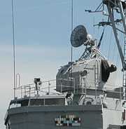
to the USA provided the USN with crucial data on UK and Royal Navy radar technology and fire-control radar systems. In September 1941, the first rectangular Mk 4 Fire-control radar antenna was mounted on a Mk 37 Director, and became a common feature on USN Directors by mid 1942. Soon aircraft flew faster, and in c1944 to increase speed and accuracy the Mk 4 was replaced by a combination of the Mk 12 (rectangular antenna) and Mk 22 (parabolic antenna) "orange peel" radars. (pictured) in the late 1950s, Mk. 37 directors had Western Electric Mk. 25 X-band conical-scan radars with round, perforated dishes. Finally, the circular SPG 25 antenna was mounted on top.
MK 38 Gun Fire Control System
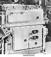
The Mk38 Gun Fire Control System (GFCS) controlled the large main battery guns of Iowa class battleships. The radar systems used by the Mk 38 GFCS were far more advanced than the primitive radar sets used by the Japanese in World War II. The major components were the director, plotting room, and interconnecting data transmission equipment. The two systems, forward and aft, were complete and independent. Their plotting rooms were isolated to protect against battle damage propagating from one to the other.Director
Radar
Radar is an object-detection system which uses radio waves to determine the range, altitude, direction, or speed of objects. It can be used to detect aircraft, ships, spacecraft, guided missiles, motor vehicles, weather formations, and terrain. The radar dish or antenna transmits pulses of radio...
. (The fire control radar was the preferred method.) The present position of the target was called the Line-Of-Sight (LOS), and it was continuously sent down to the plotting room by synchro motors
Synchro
A synchro is a type of rotary electrical transformer that is used for measuring the angle of a rotating machine such as an antenna platform. In its general physical construction, it is much like an electric motor...
. When not using the radar's display to determine Spots, the director was the optical spotting station.
Plotting Room
Parallax
Parallax is a displacement or difference in the apparent position of an object viewed along two different lines of sight, and is measured by the angle or semi-angle of inclination between those two lines. The term is derived from the Greek παράλλαξις , meaning "alteration"...
Correctors, Fire Control Switchboard, battle telephone switchboard, battery status indicators, assistant Gunnery Officers, and Fire Control Technicians (FT's).
Analog computer
An analog computer is a form of computer that uses the continuously-changeable aspects of physical phenomena such as electrical, mechanical, or hydraulic quantities to model the problem being solved...
whose function was to continuously calculate the gun's bearing and elevation, Line-Of-Fire (LOF), to hit a future position of the target. It did this by automatically receiving information from the director (LOS), the FC Radar (range), the ship's gyrocompass
Gyrocompass
A gyrocompass is a type of non-magnetic compass which bases on a fast-spinning disc and rotation of our planet to automatically find geographical direction...
(true ship's course), the ships Pitometer log
Pitometer log
Pitometer logs are devices used to measure a ship's speed relative to the water. They are used on both surface ships and submarines...
(ship's speed), the Stable Vertical (ship's deck tilt, sensed as level and crosslevel), and the ship's anemometer (relative wind speed and direction). Also, before the surface action started, the FT's made manual inputs for the average initial velocity of the projectiles fired out of the battery's gun barrels, and air density. With all this information, the rangekeeper calculated the relative motion between its ship and the target. It then could calculate an offset angle and change of range between the target's present position (LOS) and future position at the end of the projectile's time of flight. To this bearing and range offset, it added corrections for gravity, wind, Magnus Effect
Magnus effect
The Magnus effect is the phenomenon whereby a spinning object flying in a fluid creates a whirlpool of fluid around itself, and experiences a force perpendicular to the line of motion...
of the spinning projectile, stabilizing signals originating in the Stable Vertical, Earth's curvature, and Coriolis effect
Coriolis effect
In physics, the Coriolis effect is a deflection of moving objects when they are viewed in a rotating reference frame. In a reference frame with clockwise rotation, the deflection is to the left of the motion of the object; in one with counter-clockwise rotation, the deflection is to the right...
. The result was the turret's bearing and elevation orders (LOF). During the surface action, range and deflection Spots and target altitude (not zero during Gun Fire Support) were manually entered.
The Mk 13 FC Radar supplied present target range, and it showed the fall of shot around the target so the Gunnery Officer could correct the system's aim with range and deflection spots put into the rangekeeper. It could also automatically track the target by controlling the director's bearing power drive. Because of radar, Fire Control systems are able to track and fire at targets at a greater range and with increased accuracy during the day, night, or inclement weather. This was demonstrated in November 1942 when the battleship engaged the Imperial Japanese Navy
Imperial Japanese Navy
The Imperial Japanese Navy was the navy of the Empire of Japan from 1869 until 1947, when it was dissolved following Japan's constitutional renunciation of the use of force as a means of settling international disputes...
battlecruiser
Battlecruiser
Battlecruisers were large capital ships built in the first half of the 20th century. They were developed in the first decade of the century as the successor to the armoured cruiser, but their evolution was more closely linked to that of the dreadnought battleship...
Kirishima
Japanese battleship Kirishima
was a warship of the Imperial Japanese Navy during World War I and World War II. Designed by British naval engineer George Thurston, she was the third launched of the four Kongō-class battlecruisers, among the most heavily armed ships in any navy when built...
at a range of 18500 yards (16,916.4 m) at night. The engagement left Kirishima in flames, and she was ultimately scuttled by her crew. This gave the United States Navy a major advantage in World War II, as the Japanese did not develop radar or automated fire control to the level of the US Navy and were at a significant disadvantage.
The parallax
Parallax
Parallax is a displacement or difference in the apparent position of an object viewed along two different lines of sight, and is measured by the angle or semi-angle of inclination between those two lines. The term is derived from the Greek παράλλαξις , meaning "alteration"...
correctors are needed because the turrets are located hundreds of feet from the director. There is one for each turret, and each has the turret and director distance manually set in. They automatically received relative target bearing (bearing from own ship's bow), and target range. They corrected the bearing order for each turret so that all rounds fired in a salvo converged on the same point.
The assistant Gunnery Officers and Fire Control Technicians operated the equipment, talked to the turrets and ship's command by sound-powered telephone
Sound-powered telephone
A sound-powered telephone is a communication device that allows users to talk to each other with the use of a handset, similar to a conventional telephone, but without the use of external power...
, and watched the Rangekeeper's dials and system status indicators for problems. If a problem arose, they could correct the problem, or reconfigure the system to mitigate its effect.
MK 51 Fire Control System
MK 56 Gun Fire Control System (GFCS)
This GFCS was an intermediate-range, anti-aircraft gun fire-control system. It was designed for use against high-speed subsonic aircraft. It could also be used against surface targets. It was a dual ballistic system. This means that it was capable of simultaneously producing gun orders for two different gun types (eg: 5"/38cal and 3"/50cal) against the same target. Its Mk 35 Radar was capable of automatic tracking in bearing, elevation, and range that was as accurate as any optical tracking. The whole system could be controlled from the below decks Plotting Room with or without the director being manned. This allowed for rapid target acquisition when a target was first detected and designated by the ship's air-search radar, and not yet visible from on deck. Its target solution time was less than 2 seconds after Mk 35 radar "Lock on". It was designed toward the end of World War II, apparently in response to Japanese kamikaze aircraft attacks. It was conceived by Ivan Getting, mentioned near the end of his Oral history, and its linkage computer was designed by Antonín Svoboda. Its gun director was not shaped like a box, and it had no optical rangefinder. The system was manned by crew of four. On the left side of the director, was the Cockpit where the Control Officer stood behind the sitting Director Operator (Also called Dirctor Pointer). Below decks in Plot, was the Mk 4 Radar Console where the Radar Operator and Radar Tracker sat. The director's movement in bearing was unlimited because it had slip-rings in its pedestal. (The Mk. 37 gun director had a cable connection to the hull, and occasionally had to be "unwound".) Fig. 26E8 on this Web page shows the director in considerable detail.The explanatory drawings of the system show how it works, but are wildly different in physical appearance from the actual internal mechanisms, perhaps intentionally so. However, it omits any significant description of the mechanism of the linkage computer. That chapter is an excellent detailed reference that explains much of the system's design, which is quite ingenious and forward-thinking in several respects.
In the 1968 upgrade to the for service off Vietnam, three Mark 56 Gun Fire Control Systems were installed. Two on either side just forward of the aft stack, and one between the aft mast and the aft Mk 38 Director tower. This increased New Jerseys anti-aircraft capability, because the Mk 56 system could track and shoot at faster planes.
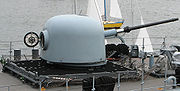
MK 68 Gun Fire Control System (GFCS)
,_front.jpg)
The gun director was mounted in a large yoke, and the whole director was stabilized in crosslevel (the yoke's pivot axis). That axis was in a vertical plane that included the line of sight.
At least in 1958, the computer was the Mk. 47, an hybrid electronic/electromechanical system. Somewhat akin to the Mk. 1A, it had electrical high-precision resolvers instead of the mechanical one of earlier machines, and multiplied with precision linear potentiometers. However, it still had disc/roller integrators as well as shafting to interconnect the mechanical elements. Whereas access to much of the Mk. 1A required time-consuming and careful disassembly (think days in some instances, and possibly a week to gain access to deeply buried mechanisms), the Mark 47 was built on thick support plates mounted behind the front panels on slides that permitted its six major sections to be pulled out of its housing for easy access to any of its parts. (The sections, when pulled out, moved fore and aft; they were heavy, not counterbalanced. Typically, a ship rolls through a much larger angle than it pitches.) The Mk. 47 probably had 3-D cams for ballistics, but information on it appears very difficult to obtain.
Mechanical connections between major sections were via shafts in the extreme rear, with couplings permitting disconnection without any attention, and probably relief springs to aid re-engagement. One might think that rotating an output shaft by hand in a pulled-out section would misalign the computer, but the type of data transmission of all such shafts did not represent magnitude; only the incremental rotation of such shafts conveyed data, and it was summed by differentials at the receiving end. One such kind of quantity is the output from the roller of a mechanical integrator; the position of the roller at any given time is immaterial; it is only the incrementing and decrementing that counts.
Whereas the Mk. 1/1A computations for the stabilizing component of gun orders had to be approximations, they were theoretically exact in the Mk. 47 computer, computed by an electrical resolver chain.
The design of the computer was based on a re-thinking of the fire control problem; it was regarded quite differently.
Production of this system lasted for over 25 years. A digital upgrade was available from 1975 to 1985, and it was in service into the 2000s. The digital upgrade was evolved for use in the Arleigh Burke-class
Arleigh Burke class destroyer
The Arleigh Burke class of guided missile destroyers is the United States Navy's first class of destroyer built around the Aegis combat system and the SPY-1D multi-function phased array radar. The class is named for Admiral Arleigh "31-Knot" Burke, the most famous American destroyer officer of...
of destroyers.
The AN/SPG-53 was a United States Navy gun fire-control radar
Fire-control radar
A fire-control radar is a radar which is designed specifically to provide information to a fire-control system in order to calculate a firing solution...
used in conjunction with the Mark 68 gun fire-control system. It was used with the 5"/54 caliber Mark 42 gun system aboard Belknap-class cruisers
Belknap class cruiser
The Belknap class cruiser was a class of single-ended guided missile cruisers built for the United States Navy during the 1960s...
, Mitscher-class destroyers
Mitscher class destroyer
The Mitscher class destroyer was an experimental destroyer class of four ships that were built for the United States Navy shortly after World War II. Considerably larger than all previous destroyers, they would have been the first post-war destroyer class had they not been reclassified during...
, Forrest Sherman-class destroyers
Forrest Sherman class destroyer
The 18 Forrest Sherman-class destroyers were the first US post-war destroyers . and later ships were equipped with B&W Bailey Meter Company's new automatic boiler combustion control system, and a modified hurricane bow/anchor configuration...
, Farragut-class destroyers
Farragut class destroyer (1958)
The Farragut class was the second destroyer class of the United States Navy to be named for Admiral David Glasgow Farragut. The class is sometimes referred to as the Coontz class, since Coontz was first to be designed and built as a guided missile ship, whereas the previous three ships were...
, Charles F. Adams-class destroyers
Charles F. Adams class destroyer
The Charles F. Adams class is a ship class of 29 guided missile destroyers built between 1958 and 1967. Twenty three ships were built for the United States Navy, 3 for the Royal Australian Navy, and 3 for the West German Bundesmarine. The ships were based on the existing Forrest Sherman class, but...
, Knox-class frigates
Knox class frigate
Knox class frigates were United States Navy warships, originally laid down as ocean escorts , but were all redesignated as frigates on 30 June 1975 in the USN 1975 ship reclassification and their hull designation changed from DE to FF.A sub-class of the Knox class was built, commonly referred to as...
as well as others.
MK 86 Gun Fire Control System (GFCS)
USS Port Royal (CG-73)
USS Port Royal is a United States Navy guided missile cruiser, the 27th and final in the class. She is the second U.S. warship to bear the name of two naval battles of Port Royal Sound, South Carolina, of the American Revolutionary War and the American Civil War...
was commissioned in July 1994.
The Mk 86 on Aegis-class ships controls the ship's 5"/54 caliber Mk 45 gun mounts, and can engage up to two targets at a time. It also uses a Remote Optical Sighting system which uses a TV camera with a telephoto zoom lens mounted on the mast and each of the illuminating radars.
MK 34 Gun Weapon System (GWS)
Arleigh Burke class destroyer
The Arleigh Burke class of guided missile destroyers is the United States Navy's first class of destroyer built around the Aegis combat system and the SPY-1D multi-function phased array radar. The class is named for Admiral Arleigh "31-Knot" Burke, the most famous American destroyer officer of...
, the only operational class of destroyers in the US. It combines the MK 45 5"/54 Caliber Gun Mount, MK 46 MOD 0 Optical Sight System and the MK 160 Mod 4 Gunfire Control System / Gun Computer System. It can be used against surface ship and close hostile aircraft, and as Naval Gunfire Support (NGFS) against shore targets.
MK 92 Fire Control System (FCS)
Oliver Hazard Perry class frigate
The Oliver Hazard Perry class is a class of frigates named after the American Commodore Oliver Hazard Perry, the hero of the naval Battle of Lake Erie...
to control the MK 75 Naval Gun and the MK 13 Guided Missile Launching System (missiles have since been removed since retirement of its version of the Standard missile). The Mod 1 system used in PHMs
Pegasus class hydrofoil
The Pegasus-class hydrofoils were a series of fast attack patrol boats employed by the U.S. Navy. They were in service from 1977 through 1993...
(retired) and the US Coast Guard's WMEC
USCG Medium Endurance Cutter
The United States Coast Guard's cutter fleet contains numerous smaller vessels, and about three dozen large icebreakers, High endurance cutters, Medium Endurance cutters, and three National Security Cutters. There are two legacy vessels, the Alex Haley and the Acushnet.There are 13 vessels in the...
and WHEC ships can track one air or surface target using the monopulse tracker and two surface or shore targets. FFG 7 class frigates with the Mod 2 system can track an additional air or surface target using the Separate Track Illuminating Radar (STIR).
Mk 110 57 mm gun
The Mk 110 57 mm gun is the newest multi-purpose, medium caliber gun. It's based on the Bofors 57 Mk 3Bofors 57 mm gun
The Bofors 57 mm guns are a series of dual-purpose naval guns designed and produced by the Swedish defence firm of Bofors Defence...
. Compared to World War II destroyers or escorts fitted with 2 or 5 five-inch guns which could fire 15 rounds per minute per barrel, the single Mk 110 can fire salvos at up to 220 rounds per minute, up to a similar range of nine miles with minimal manpower in a turret with a stealthy radar signature. Linked to a digital fire control system, servo-controlled electro hydraulic gun laying subsystems provide extreme pointing accuracy, even in heavy seas. Current and proposed mountings for the weapon include the United States Coast Guard
United States Coast Guard
The United States Coast Guard is a branch of the United States Armed Forces and one of the seven U.S. uniformed services. The Coast Guard is a maritime, military, multi-mission service unique among the military branches for having a maritime law enforcement mission and a federal regulatory agency...
's National Security Cutter
National Security Cutter
The United States Coast Guard National Security Cutter , also known as the Legend class and Maritime Security Cutter, Large, is one design among several new cutter designs developed as part of the Integrated Deepwater System Program....
, the upcoming Zumwalt-class destroyer (close-in), and the new Littoral combat ship
Littoral combat ship
A Littoral Combat Ship is a type of relatively small surface vessel intended for operations in the littoral zone . It is "envisioned to be a networked, agile, stealthy surface combatant capable of defeating anti-access and asymmetric threats in the littorals." Two ship classes are the first...
s.
To increase lethality and flexibility, the ammunition comes equipped with a smart programmable fuze with six modes: contact, delay, time, and 3 proximity modes.
See also
- Director (military)Director (military)A director, also called an auxiliary predictor, is a mechanical or electronic computer that continuously calculates trigonometric firing solutions for use against a moving target, and transmits targeting data to direct the weapon firing crew....
- Fire-control systemFire-control systemA fire-control system is a number of components working together, usually a gun data computer, a director, and radar, which is designed to assist a weapon system in hitting its target. It performs the same task as a human gunner firing a weapon, but attempts to do so faster and more...
Ground, sea and air based systems - HACSHACSHACS, an acronym of High Angle Control System, was a British anti-aircraft fire-control system employed by the Royal Navy from 1931 onwards and used widely during World War II...
- British A/A gun control system - Mathematical discussion of rangekeepingMathematical discussion of rangekeepingIn naval gunnery, when long-range guns became available, an enemy ship would move some distance after the shells were fired. It became necessary to figure out where the enemy ship, the target, was going to be when the shells arrived...
- RangekeeperRangekeeperRangekeepers were electromechanical fire control computers used primarily during the early part of the 20th century. They were sophisticated analog computers whose development reached its zenith following World War II, specifically the Computer Mk 47 in the Mk 68 Gun Fire Control system. During...
shipboard analog fire control computer
External links
- The British High Angle Control System (HACS)
- Best Battleship Fire control—Comparison of World War II battleship systems
- Appendix one, Classification of Director Instruments
- HACS III Operating manual Part 1
- HACS III Operating manual Part 2
- USS Enterprise Action Log
- The RN Pocket Gunnery Book
- Fire Control Fundamentals
- Manual for the Mark 1 and Mark 1a Computer
- Maintenance Manual for the Mark 1 Computer
- Manual for the Mark 6 Stable Element