
Mathematical discussion of rangekeeping
Encyclopedia
In naval gunnery, when long-range guns became available, an enemy ship would move some distance after the shells were fired. It became necessary to figure out where the enemy ship, the target, was going to be when the shells arrived. The process of keeping track of where the ship was likely to be was called rangekeeping, because the distance to the target—the range—was a very important factor in aiming the guns accurately. As time passed, train (also called bearing), the direction to the target, also became part of rangekeeping, but tradition kept the term alive.
Rangekeeping is an excellent example of the application of analog computing to a real-world mathematical modeling problem. Because nations had so much money invested in their capital ships, they were willing to invest enormous amounts of money in the development of rangekeeping hardware to ensure that the guns of these ships could put their projectiles on target. This article presents an overview of the rangekeeping as a mathematical modeling problem. To make this discussion more concrete, the Ford Mk 1 Rangekeeper is used as the focus of this discussion. The Ford Mk 1 Rangekeeper was first deployed on the USS Texas
in 1916 during World War I
. This is a relatively well documented rangekeeper that had a long service life. While an early form of mechanical rangekeeper, it does illustrate all the basic principles. The rangekeepers of other nations used similar algorithms for computing gun angles, but often differed dramatically in their operational use.
In addition to long range gunnery, the launching of torpedo
es also requires a rangekeeping-like function. The US Navy during World War II
had the TDC
, which was the only World War II-era submarine torpedo fire control system to incorporate a mechanical rangekeeper (other navies depended on manual methods). There were also rangekeeping devices for use with surface ship-launched torpedoes. For a view of rangekeeping outside that of the US Navy, there is a detailed reference that discusses the rangekeeping mathematics associated with torpedo fire control in the Imperial Japanese Navy
.
The following discussion is patterned after the presentations in World War II US Navy gunnery manuals.
 US Navy rangekeeper
s during World War II
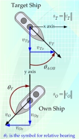
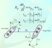
used a moving coordinate system based on the line of sight (LOS) between the ship firing its gun (known as the "own ship") and the target (known as the "target"). As is shown in Figure 1, the rangekeeper defines the "y axis" as the LOS and the "x axis" as a perpendicular to the LOS with the origin of the two axes centered on the target.
An important aspect of the choice of coordinate system is understanding the signs of the various rates. The rate of bearing change is positive in the clockwise direction. The rate of range is positive for increasing target range.
In addition to ship-board target observations, rangekeepers could also take input from spotting aircraft or even manned balloons
tethered to the own ship. These spotting platforms could be launched and recovered from large warships, like battleships. In general, target observations made by shipboard instruments were preferred for targets at ranges of less than 20,000 yards and aircraft observations were preferred for longer range targets. After World War II, helicopters became available and the need to conduct the dangerous operations of launching and recovering spotting aircraft or balloons was eliminated (see Iowa class battleship for a brief discussion).
During World War I, target tracking information was often presented on a sheet of paper. During World War II, the tracking information could be displayed on electronic displays (see Essex class aircraft carrier for a discussion of the common displays).
than the optical rangefinders (at least under operational conditions) and was the preferred way to determine target range during both night and day.
The speed and course of the target could be computed using the distance the target traveled over an interval of time. During the latter part of World War II, the speed of the target could be measured using radar data. Radar provided accurate bearing rate, range, and radial speed, which was converted to target course and speed.
In some cases, such as with submarines, the target speed could be estimated using sonar data. For example, the sonar operator could measure the propeller turn rate acoustically and, knowing the ship's class
, compute the ship's speed (see TDC
for more information).
 The target course was the most difficult piece of target data to obtain. In many cases, instead of measuring target course many systems measured a related quantity called angle on the bow. Angle on the bow is the angle made by the ship's course and the line of sight (see Figure 1).
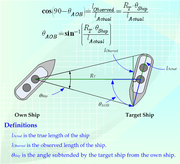
The angle on the bow was usually estimated based on the observational experience of the observer. In some cases, the observers improved their estimation abilities by practicing against ship models mounted on a "lazy Susan"
. The Imperial Japanese Navy
had a unique tool, called Sokutekiban (測敵盤), that was used to assist observers with measuring angle on the bow. The observer would first use this device to measure the angular width of the target. Knowing the angular width of the target, the range to the target, and the known length of that ship class
, the angle on the bow of the target can be computed using equations shown in Figure 2.
Human observers were required to determine the angle on the bow. To confuse the human observers, ships often used dazzle camouflage
, which consisted of painting lines on a ship in an effort to make determining a target's angle on the bow difficult. While dazzle camouflage was useful against some types of optical rangefinders, this approach was useless against radar and it fell out of favor during World War II.
During World War I, rangekeepers were often referred to as "clocks" (e.g. see range and bearing clocks in the Dreyer Fire Control Table). These devices were called clocks because they regularly incremented the target range and angle estimates using fixed values. This approach was of limited use because the target bearing changes are a function of range and using a fixed change causes the target bearing prediction to quickly become inaccurate.
 The target range at the time of projectile impact can be estimated using Equation 1, which is illustrated in Figure 3.
where
The exact prediction of the target range at the time of projectile impact is difficult because it requires knowing the projectile time of flight, which is a function of the projected target position. While this calculation can be performed using a trial and error approach, this was not a practical approach with the analog computer
hardware available during World War II. In the case of the Ford Rangekeeper Mk 1, the time of flight was approximated by assuming the time of flight was linearly proportional to range, as is shown in Equation 2.
where
The assumption of TOF being linearly proportional to range is a crude one and could be improved through the use of more sophisticated means of function evaluation.
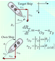
Range prediction requires knowing the rate of range change. As is shown in Figure 3, the rate of range change can be expressed as shown in Equation 3.
where
Equation 4 shows the complete equation for the predicted range.
 The prediction of azimuth is performed similarly to the range prediction. Equation 5 is the fundamental relationship, whose derivation is illustrated in Figure 4.
where
The rate of bearing change can be computed using Equation 6, which is illustrated in Figure 4.
where
Substituting , Equation 7 shows the final formula for the predicted bearing.
 Firing artillery at targets beyond visual range historically has required computations based on firing tables.
The impact point of a projectile is a function of many variables:
The firing tables provide data for an artillery piece firing under standardized conditions and the corrections required to determine the point of impact under actual conditions. There were a number of ways to implement a firing table using cams. Consider Figure 5 for example. In this case the gun angle as a function of target's range and the target's relative elevation is represented by the thickness of the cam at a given axial distance and angle. A gun direction officer would input the target range and relative elevation using dials. The pin height then represents the required gun angle. This pin height could be used to drive cams or gears that would make other corrections, such as for propellant temperature and projectle type.
The cams used in a rangekeeper needed to be very precisely machined in order to accurately direct the guns. Because these cams were machined to specifications composed of data tables, they became an early application of CNC machine tools.
In addition to the target and ballistic corrections, the rangekeeper must also correct for the ships undulating motion. The warships had a gyroscope with its spin axis vertical. This gyro determined two angles that defined the tilt of the ship's deck with respect to the vertical. Those two angle were fed to the rangekeeper, which applied a correction based on these angles.
While the rangekeeper designers spent an enormous amount of time working to minimize the sources of error in the rangekeeper calculations, there were errors and information uncertainties that contributed to projectiles missing their targets on the first shot. The rangekeeper had dials that allowed manual corrections to be incorporated into the rangekeeper firing solution. When artillery spotters would call in a correction, the rangekeeper operators would manually incorporate the correction using these dials.
Rangekeeping is an excellent example of the application of analog computing to a real-world mathematical modeling problem. Because nations had so much money invested in their capital ships, they were willing to invest enormous amounts of money in the development of rangekeeping hardware to ensure that the guns of these ships could put their projectiles on target. This article presents an overview of the rangekeeping as a mathematical modeling problem. To make this discussion more concrete, the Ford Mk 1 Rangekeeper is used as the focus of this discussion. The Ford Mk 1 Rangekeeper was first deployed on the USS Texas
USS Texas (BB-35)
USS Texas , the second ship of the United States Navy named in honor of the U.S. state of Texas, is a . The ship was launched on 18 May 1912 and commissioned on 12 March 1914....
in 1916 during World War I
World War I
World War I , which was predominantly called the World War or the Great War from its occurrence until 1939, and the First World War or World War I thereafter, was a major war centred in Europe that began on 28 July 1914 and lasted until 11 November 1918...
. This is a relatively well documented rangekeeper that had a long service life. While an early form of mechanical rangekeeper, it does illustrate all the basic principles. The rangekeepers of other nations used similar algorithms for computing gun angles, but often differed dramatically in their operational use.
In addition to long range gunnery, the launching of torpedo
Torpedo
The modern torpedo is a self-propelled missile weapon with an explosive warhead, launched above or below the water surface, propelled underwater towards a target, and designed to detonate either on contact with it or in proximity to it.The term torpedo was originally employed for...
es also requires a rangekeeping-like function. The US Navy during World War II
World War II
World War II, or the Second World War , was a global conflict lasting from 1939 to 1945, involving most of the world's nations—including all of the great powers—eventually forming two opposing military alliances: the Allies and the Axis...
had the TDC
Torpedo Data Computer
The Torpedo Data Computer was an early electromechanical analog computer used for torpedo fire-control on American submarines during World War II . Britain, Germany, and Japan also developed automated torpedo fire control equipment, but none were as advanced as US Navy's TDC...
, which was the only World War II-era submarine torpedo fire control system to incorporate a mechanical rangekeeper (other navies depended on manual methods). There were also rangekeeping devices for use with surface ship-launched torpedoes. For a view of rangekeeping outside that of the US Navy, there is a detailed reference that discusses the rangekeeping mathematics associated with torpedo fire control in the Imperial Japanese Navy
Imperial Japanese Navy
The Imperial Japanese Navy was the navy of the Empire of Japan from 1869 until 1947, when it was dissolved following Japan's constitutional renunciation of the use of force as a means of settling international disputes...
.
The following discussion is patterned after the presentations in World War II US Navy gunnery manuals.
Coordinate System
Rangekeeper
Rangekeepers were electromechanical fire control computers used primarily during the early part of the 20th century. They were sophisticated analog computers whose development reached its zenith following World War II, specifically the Computer Mk 47 in the Mk 68 Gun Fire Control system. During...
s during World War II
World War II
World War II, or the Second World War , was a global conflict lasting from 1939 to 1945, involving most of the world's nations—including all of the great powers—eventually forming two opposing military alliances: the Allies and the Axis...
used a moving coordinate system based on the line of sight (LOS) between the ship firing its gun (known as the "own ship") and the target (known as the "target"). As is shown in Figure 1, the rangekeeper defines the "y axis" as the LOS and the "x axis" as a perpendicular to the LOS with the origin of the two axes centered on the target.
An important aspect of the choice of coordinate system is understanding the signs of the various rates. The rate of bearing change is positive in the clockwise direction. The rate of range is positive for increasing target range.
General Approach
During World War II, tracking a target meant knowing continuously the target's range and bearing. These target parameters were sampled periodically by sailors manning gun directors and radar systems, who then fed the data into a rangekeeper. The rangekeeper performed an linear extrapolation of the target range and bearing as a function of time based on the target information samples.In addition to ship-board target observations, rangekeepers could also take input from spotting aircraft or even manned balloons
Observation balloon
Observation balloons are balloons that are employed as aerial platforms for intelligence gathering and artillery spotting. Their use began during the French Revolutionary Wars, reaching their zenith during World War I, and they continue in limited use today....
tethered to the own ship. These spotting platforms could be launched and recovered from large warships, like battleships. In general, target observations made by shipboard instruments were preferred for targets at ranges of less than 20,000 yards and aircraft observations were preferred for longer range targets. After World War II, helicopters became available and the need to conduct the dangerous operations of launching and recovering spotting aircraft or balloons was eliminated (see Iowa class battleship for a brief discussion).
During World War I, target tracking information was often presented on a sheet of paper. During World War II, the tracking information could be displayed on electronic displays (see Essex class aircraft carrier for a discussion of the common displays).
Range to Target
Early in World War II, the range to the target was measured by optical rangefinders. Though some night operations were conducted using searchlights and star shells, in general optical rangefinders were limited to daytime operation. During the latter part of World War II, radar was used to determine the range to the target. Radar proved to be more accuratethan the optical rangefinders (at least under operational conditions) and was the preferred way to determine target range during both night and day.
Speed of the Target
Early in World War II, target range and bearing measurements were taken over a period of time and plotted manually on a chart.The speed and course of the target could be computed using the distance the target traveled over an interval of time. During the latter part of World War II, the speed of the target could be measured using radar data. Radar provided accurate bearing rate, range, and radial speed, which was converted to target course and speed.
In some cases, such as with submarines, the target speed could be estimated using sonar data. For example, the sonar operator could measure the propeller turn rate acoustically and, knowing the ship's class
Ship class
A ship class is a group of ships of a similar design. This is distinct from a ship-type, which might reflect a similarity of tonnage or intended use. For example, the is a nuclear aircraft carrier of the Nimitz class....
, compute the ship's speed (see TDC
Torpedo Data Computer
The Torpedo Data Computer was an early electromechanical analog computer used for torpedo fire-control on American submarines during World War II . Britain, Germany, and Japan also developed automated torpedo fire control equipment, but none were as advanced as US Navy's TDC...
for more information).
Course of the Target
The angle on the bow was usually estimated based on the observational experience of the observer. In some cases, the observers improved their estimation abilities by practicing against ship models mounted on a "lazy Susan"
Lazy Susan
A Lazy Susan is a rotating tray, usually circular, placed on top of a table to aid in moving food on a large table or countertop.- Origin :The term "Lazy Susan" made its first written appearance in a Good Housekeeping article in 1906, although their existence dates back to the 18th century...
. The Imperial Japanese Navy
Imperial Japanese Navy
The Imperial Japanese Navy was the navy of the Empire of Japan from 1869 until 1947, when it was dissolved following Japan's constitutional renunciation of the use of force as a means of settling international disputes...
had a unique tool, called Sokutekiban (測敵盤), that was used to assist observers with measuring angle on the bow. The observer would first use this device to measure the angular width of the target. Knowing the angular width of the target, the range to the target, and the known length of that ship class
Ship class
A ship class is a group of ships of a similar design. This is distinct from a ship-type, which might reflect a similarity of tonnage or intended use. For example, the is a nuclear aircraft carrier of the Nimitz class....
, the angle on the bow of the target can be computed using equations shown in Figure 2.
Human observers were required to determine the angle on the bow. To confuse the human observers, ships often used dazzle camouflage
Dazzle camouflage
Dazzle camouflage, also known as Razzle Dazzle or Dazzle painting, was a camouflage paint scheme used on ships, extensively during World War I and to a lesser extent in World War II...
, which consisted of painting lines on a ship in an effort to make determining a target's angle on the bow difficult. While dazzle camouflage was useful against some types of optical rangefinders, this approach was useless against radar and it fell out of favor during World War II.
Position Prediction
The prediction of the target ship's position at the time of projectile impact is critical because that is the position at which the own ship's guns must be directed. During World War II, most rangekeepers performed position prediction using a linear extrapolation of the target's course and speed. While ships are maneuverable, the large ships maneuver slowly and linear extrapolation is a reasonable approach in many cases.During World War I, rangekeepers were often referred to as "clocks" (e.g. see range and bearing clocks in the Dreyer Fire Control Table). These devices were called clocks because they regularly incremented the target range and angle estimates using fixed values. This approach was of limited use because the target bearing changes are a function of range and using a fixed change causes the target bearing prediction to quickly become inaccurate.
Predicted Range
| (Equation 1) | 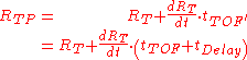 |
|---|
where
-
 is the range to the target at the time of projectile impact.
 -
 is the range to the target at the time of gun firing.
 -
 is the projectile time of flight
  plus system
firing delays , i.e.
  .
.
The exact prediction of the target range at the time of projectile impact is difficult because it requires knowing the projectile time of flight, which is a function of the projected target position. While this calculation can be performed using a trial and error approach, this was not a practical approach with the analog computer
Analog computer
An analog computer is a form of computer that uses the continuously-changeable aspects of physical phenomena such as electrical, mechanical, or hydraulic quantities to model the problem being solved...
hardware available during World War II. In the case of the Ford Rangekeeper Mk 1, the time of flight was approximated by assuming the time of flight was linearly proportional to range, as is shown in Equation 2.
| (Equation 2) |  |
|---|
where
-
 is the constant of proportionality between time of flight (TOF) and target range.
The assumption of TOF being linearly proportional to range is a crude one and could be improved through the use of more sophisticated means of function evaluation.
Range prediction requires knowing the rate of range change. As is shown in Figure 3, the rate of range change can be expressed as shown in Equation 3.
| (Equation 3) | 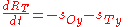 |
|---|
where
-
 is the own ship speed along the LOS where
  .
. -
 is the target ship speed along the LOS where
  .
.
Equation 4 shows the complete equation for the predicted range.
| (Equation 4) |  |
|---|
Predicted Azimuth (Train)
| (Equation 5) |  |
|---|
where
-
 is the azimuth to the target at the time of gun firing.
 -
 is the azimuth to the target at the time of projectile impact.
The rate of bearing change can be computed using Equation 6, which is illustrated in Figure 4.
| (Equation 6) | 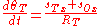 |
|---|
where
-
 is the own ship speed along the x axis, i.e.
  .
. -
 is the target speed along the x axis, i.e.
  .
.
Substituting
, Equation 7 shows the final formula for the predicted bearing.
| (Equation 7) | 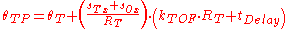 |
|---|
Ballistic Correction
The impact point of a projectile is a function of many variables:
- Air temperature
- Air density
- Wind
- Range
- Earth rotation
- Projectile, fuze, weapon characteristics
- Muzzle velocity
- Propellant temperature
- Drift
- Parallax between the guns and the rangefinders and radar systems
- Elevation difference between target and artillery piece
The firing tables provide data for an artillery piece firing under standardized conditions and the corrections required to determine the point of impact under actual conditions. There were a number of ways to implement a firing table using cams. Consider Figure 5 for example. In this case the gun angle as a function of target's range and the target's relative elevation is represented by the thickness of the cam at a given axial distance and angle. A gun direction officer would input the target range and relative elevation using dials. The pin height then represents the required gun angle. This pin height could be used to drive cams or gears that would make other corrections, such as for propellant temperature and projectle type.
The cams used in a rangekeeper needed to be very precisely machined in order to accurately direct the guns. Because these cams were machined to specifications composed of data tables, they became an early application of CNC machine tools.
In addition to the target and ballistic corrections, the rangekeeper must also correct for the ships undulating motion. The warships had a gyroscope with its spin axis vertical. This gyro determined two angles that defined the tilt of the ship's deck with respect to the vertical. Those two angle were fed to the rangekeeper, which applied a correction based on these angles.
While the rangekeeper designers spent an enormous amount of time working to minimize the sources of error in the rangekeeper calculations, there were errors and information uncertainties that contributed to projectiles missing their targets on the first shot. The rangekeeper had dials that allowed manual corrections to be incorporated into the rangekeeper firing solution. When artillery spotters would call in a correction, the rangekeeper operators would manually incorporate the correction using these dials.
External links
- USN Report on IJN Torpedo Technology: This report shows that the Imperial Japanese Navy used a similar approach to the US Navy for the rangekeeping function.
- British Fire Control: British gunnery manual that discusses their approach to long range gun direction.
- Firing Tables: Powerpoint presentation on firing tables