
Doubly-fed electric machine
Encyclopedia
Doubly fed electric machines are electric motor
s or electric generators that have windings on both stationary and rotating parts, where both windings transfer significant power between shaft and electrical system. Doubly fed machines are useful in applications that require varying speed of the machine's shaft for a fixed power system frequency.
Examples of operational doubly fed electric machines are the conventional wound-rotor doubly fed electric machine with a multiphase slip-ring assembly, the brushless wound-rotor doubly fed electric machine, and the brushless doubly fed induction electric machines.
In practice, the classical wound-rotor doubly fed induction electric motor or generator system has known issues of instability, high maintenance and inefficiency of an integral multiphase slip-ring assembly, and discontinuity about synchronous speed where induction ceases to exist. A practical wound-rotor doubly fed electric machine system that does not rely exclusively on asynchronous (i.e., induction) principles while symmetrically motoring or generating over its entire speed range has never materialized from the electric machine establishment, despite years of research to find an evolutionary brushless, synchronous, and stable control technology. Consequently, the wound-rotor doubly fed induction electric machine has been forced into antiquity, except in large installations where efficiency and cost are critical over a limited speed range, such as wind turbines. This may change with recent Brushless Wound-Rotor Doubly Fed Electric Machine technology development.
As do all electromagnetic electric machines, doubly fed machines need torque current to produce torque. Because there are no permanent magnets with a persistent but limited flux density in the doubly fed machine, magnetizing current is also needed to produce magnetic flux. Magnetizing current and torque current are orthogonal vectors and do not add directly. Since the magnetizing current is much smaller than the torque current, it is only significant in the efficiency of the machine at very low torque. Furuthermore, magnetizing current of the wound rotor doubly fed electric machine can be shared between the stator and rotor windings for lowest I2R loss. For example, if all magnetizing current is supplied by the rotor windings, the stator will only have torque current and so unity power factor
. At synchronous speed the rotor current has to be DC, as in ordinary synchronous machines. If the shaft speed is above or below synchronous speed, the rotor current must be AC at the slip frequency. Reactive power is used in the rotor winding when it is used to magnetize the machine in non-synchronous operation.
Rotor current is also needed to produce torque in addition to magnetization. Thus active power is present in the rotor in addition to reactive power.
The frequency and the magnitude of the rotor voltage is proportional to the difference between the speed of the machine and the synchronous speed (the slip). At standstill, the frequency will be the same as the frequency in the stator; the voltage is determined by the ratio of the stator and rotor winding turns. Thus if the number of turns is equal, the rotor has the same voltage as the stator. The doubly fed machine is a transformer at standstill. The transformer-like characteristics are also present when it is rotating, manifesting itself especially during transients in the grid.
Due to the voltage and current behavior described above the rotor will either require, or generate, active power depending on the speed and torque. If the machine is producing torque and operating as a motor, the rotor will generate power if the speed is below synchronous speed (subsynchronous operation). At standstill all power fed in the stator (excluding losses) is returned via the rotor. The magnitude of the active power depends on the torque of the motor. Thus if the motor has rated torque, rated power is circulating through the stator and rotor but like all electric machines of similar rating, efficiency is based on the circulating current and not the circulating power. Like all electric machines, the efficiency of the machine is not very good at low speeds because current is required to produce torque but little or no mechanical power is produced.
If the machine is operating as a motor at speeds over the synchronous speed (supersynchronous operation), the mechanical power is fed in both through the stator and rotor. As a consequence the efficiency is now better than with singly fed motors. For example, at maximum speed the doubly fed electric machine with equal stator and rotor turns produces same torque at double speed (and thus twice the power) as a singly fed electric machine. The losses, being roughly proportional to the torque, are quite the same. Thus efficiency, which is the power taken divided by the total power produced, is better than singly fed electric machines. Naturally one has to take into account the loss of the power electronic control equipment. However, the frequency converter of the doubly fed machine has to control only 50% or less of the power of the machine, and thus has about half of the loss of the singly fed machines' frequency converter that has to pass through 100 % of the power.
Since efficiency is the ratio between the output power (i.e., input power minus the loss) to the input power, the magnetic core efficiency of a wound rotor doubly fed machine, which has just two winding sets (i.e., dual armature winding sets) of loss but shows twice the power for a given frequency and voltage of operation, is comparable to the magnetic core efficiency of permanent magnet machines with just one winding set (i.e., single armature winding set) of loss but without magnetizing current. Coupled with the low power electronic controller, the wound-rotor doubly fed electric machine system would be more efficient than permanent magnet machine systems without magnetizing current.
For operation as a generator a similar situation exists. At subsynchronous speeds the stator is generating the power but part of it has to be fed back to rotor. At supersynchronous speeds both the rotor and stator are producing power to the grid.
Thus the current rating of the rotor converter is defined by the maximum active current required by the torque production and the maximum reactive current required to magnetize the machine.
Doubly fed electric machines outperform the others in supersynchronous speeds. They can operate at constant torque to twice synchronous speed if each active winding is rated at half the total power of the machine (i.e., contiguous operation between sub-synchronous through supersynchronous speed range).
It is important to note, however, that doubly fed machines do not produce more continuous rated torque per volume than singly fed machines. The bigger power rating is due to the higher speed attainable without weakening the magnetic flux. The short time maximum torque of a wound rotor doubly fed electric machine is, however, much higher than all other electric machines, including induction or permanent magnet machines, because increasing torque current does not directly increase air-gap flux, which leads to core saturation. In practice, increasing torque current is only limited by the temperature of the windings and the maximum current capability of the rotor frequency converter but for only the doubly fed electric machine, the frequency converter is rated for half or less of the system power.
With one of the two armature winding sets (i.e., doubly fed) residing on the rotor and stator body, respectively, the rotor real estate of the wound-rotor doubly fed machine actively participates in the energy conversion process, which is different from all other electric machines, including permanent magnet synchronous machines. As a result, the magnetic core of the wound-rotor doubly fed electric machine shows highest power density.
Changing of the direction of the rotation requires the swap of two stator phases near zero speed if symmetrical speed range in both directions is required.
Further note, it is common to dimension the doubly fed machine to operate only at a narrow speed range around synchronous speed and thus further decrease the power rating (and cost) of the frequency converter in the rotor circuit.
Typical applications of doubly fed machines have been high power pumps and fans, hydro and wind generators, shaft generators for ships etc. where operating speed range has been quite narrow, less than ±30% of the synchronous speed and only small power is required in the subsynchronous range.
Due to the high rotor to stator winding turn ratio and the high voltage thus induced in the rotor at standstill, the starting of this kind of restricted operating speed range motor drive is usually done with rotor resistors in induction motor mode. When speed is in the operating speed range, the resistors are disconnected and the frequency converter is connected to the rotor. It is also possible to short circuit the stator and use the frequency converter in the induction motor control mode to accelerate the motor to the operating speed range. Generators, naturally, don't usually need any additional starting means because wind or water is used to accelerate the machine to the operating speed range.
, conditions bi-directional (i.e., four quadrant), speed synchronized, and multiphase electrical power to at least one of the winding sets (generally, the rotor winding set). Using four quadrant control, which must be continuously stable throughout the speed range, a wound-rotor doubly fed electric machine with two poles (i.e., one pole-pair) has a constant torque speed range of 7,200 rpm/120 Hz when operating at 60 Hz. However, in high power applications two or three pole-pair machines with respectively lower maximum speeds are common.
The electronic controller is smaller, less expensive, more efficient, and more compact than electronic controllers of singly fed electric machine because in the simplest configuration, only the power of the rotating (or moving) active winding set is controlled, which is less than half the total power output of the electric machine.
Due to the lack of damper windings used in synchronous machines, the wound-rotor doubly fed electric machines are susceptible to instability without stabilizing control because torque is a function of position. Pioneering work of Drs. Albertson, Long, Novotny, and Schmitz from the engineering department of the University of Wisconsin realized this must be overcome with instantaneous control. Like any synchronous machine, losing synchronism will result in alternating torque pulsation and other related consequences.
Doubly fed electric machines require electronic control for practical operation and should be considered an electric machine system or more appropriately, an adjustable-speed drive.
The doubly fed machine operation at unity stator power factor requires higher flux in the air-gap of the machine than when the machine is used as wound rotor induction machine. It is quite common that wound rotor machines not designed to doubly fed operation saturate heavily if doubly fed operation at rated stator voltage is attempted. Thus a special design for doubly fed operation is necessary.
A multiphase slip ring
assembly (i.e., sliding electrical contacts) is traditionally used to transfer power to the rotating (moving) winding set and to allow independent control of the rotor winding set. The slip ring assembly requires maintenance and compromises system reliability, cost and efficiency. Attempts to avoid the slip ring assembly are constantly being researched with limited success (see Brushless doubly fed induction electric machines).
This is especially important when operating at synchronous speed, because then the rotor current will be DC current. Without slip rings the production of DC current in the rotor winding is only possible when the frequency converter is at least partly located in the rotor and rotating with it. This kind of rotor converter naturally requires its own winding system (preferably using high frequency in the 10 kHz range for compact size) for power transfer out of or into the rotor. This kind of arrangement, which is without the cost and loss of a multiphase slip-ring assembly, would show lower cost and higher efficiency, if the two electronic stages on the rotor and stator assembly, respectively, and the intermediate winding stages were similar to the two stages of electronics and the DC link stage of the conventional electronic controller. Furthermore, there are thermal and mechanical constraints (for example centrifugal forces) of the power electronic assembly in the rotor. However, electronics have been incorporated on the rotor for many years (i.e., high speed alternators with brushless field exciters) for the improved reliability. Furthermore, high frequency power transfer is used in many applications because of improvements in efficiency and cost over low frequency alternatives, such as the DC link chokes and capacitors in traditional electronic controllers.
s. It is based on an induction generator
with a multiphase wound rotor and a multiphase slip ring assembly with brushes for access to the rotor windings. It is possible to avoid the multiphase slip ring assembly (see brushless doubly fed electric machines), but there are problems with efficiency, cost and size. A better alternative is a brushless wound-rotor doubly fed electric machine.
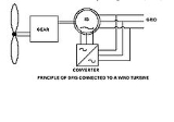
 The principle of the DFIG is that rotor windings are connected to the grid via slip rings and back-to-back voltage
source converter that controls both the rotor and the grid currents. Thus rotor
frequency
can freely differ from the grid frequency (50 or 60 Hz). By using the converter to control the rotor currents, it is possible to adjust the active and reactive power fed to the grid from the stator independently of the generator's turning speed. The control principle used is either the two-axis current vector control
or direct torque control (DTC)
. DTC has turned out to have better stability than current vector control especially when high reactive currents are required from the generator.
The doubly fed generator rotors are typically wound with 2 to 3 times the number of turns of the stator. This means that the rotor voltages will be higher and currents respectively lower. Thus in the typical ± 30 % operational speed range around the synchronous speed, the rated current of the converter is accordingly lower which leads to a lower cost of the converter. The drawback is that controlled operation outside the operational speed range is impossible because of the higher than rated rotor voltage. Further, the voltage transients due to the grid disturbances (three- and two-phase voltage dips, especially) will also be magnified. In order to prevent high rotor voltages - and high currents resulting from these voltages - from destroying the IGBTs and diode
s of the converter, a protection circuit (called crowbar
) is used.
The crowbar will short-circuit the rotor windings through a small resistance when excessive currents or voltages are detected. In order to be able to continue the operation as quickly as possible an active crowbar
has to be used. The active crowbar can remove the rotor short in a controlled way and thus the rotor side converter can be started only after 20-60 ms from the start of the grid disturbance. Thus it is possible to generate reactive current to the grid during the rest of the voltage dip and in this way help the grid to recover from the fault.
As a summary, a doubly fed induction machine is a wound-rotor doubly fed electric machine and has several advantages over a conventional induction machine in wind power applications. First, as the rotor circuit is controlled by a power electronics converter, the induction generator is able to both import and export reactive power. This has important consequences for power system stability and allows the machine to support the grid during severe voltage disturbances (low voltage ride through, LVRT)
. Second, the control of the rotor voltages and currents enables the induction machine to remain synchronized
with the grid while the wind turbine speed varies. A variable speed wind turbine utilizes the available wind resource more efficiently than a fixed speed wind turbine, especially during light wind conditions. Third, the cost of the converter is low when compared with other variable speed solutions because only a fraction of the mechanical power, typically 25-30 %, is fed to the grid through the converter, the rest being fed to grid directly from the stator. The efficiency of the DFIG is very good for the same reason.
or electric generator) is constructed by adjacently placing two multiphase winding sets with unlike pole-pairs on the stator
body. With unlike pole-pairs between the two winding sets, low frequency magnetic induction is assured over the speed range. One of the stator winding sets (power winding) is connected to the grid and the other winding set (control winding) is supplied from a frequency converter. The shaft speed is adjusted by varying the frequency of the control winding. As a doubly fed electric machine, the rating of the frequency converter need only be fraction of the machine rating.
The brushless doubly fed electric machine does not utilize core real-estate efficiently and the dual winding set stator assembly is physically larger than other electric machines of comparable power rating. In addition, a specially designed rotor assembly tries to focus most of the mutual magnetic field
to follow an indirect path across the air-gap and through the rotor assembly for inductive coupling (i.e., brushless) between the two adjacent winding sets. As a result, the adjacent winding sets are excited independently and actively participate in the electro-mechanical energy conversion process, which is a criterion of doubly fed electric machines.
The type of rotor assembly determines if the machine is a reluctance or induction
doubly fed electric machine. The constant torque
speed range is always less than 1800 rpm @ 60 Hz
because the effective pole count is the average of the unlike pole-pairs of the two active winding sets. Brushless doubly fed electric machines incorporate a poor electromagnetic design that compromises physical size, cost, and electrical efficiency, to chiefly avoid a multiphase slip ring
assembly. Although brushless doubly fed electric machines have not seen commercial success since their conception in the early 1970s, the promise of a low cost, highly efficient electronic controller keeps the concept under perpetual study, research, and development.
or electric generator) incorporates the electromagnetic structure of the wound-rotor doubly fed electric machine, but replaces the traditional multiphase slip ring assembly with a brushless means to independently power the rotor winding set (i.e., doubly fed) with multiphase AC power. Without relying on slip for operation, the brushless wound-rotor doubly fed electric machine should never be confused with brushless doubly fed induction electric machines, which rely on very different principles of unlike pole-pair induction for operation. Likewise without an independent means of exciting the rotor winding set, the torque of the wound-rotor doubly fed electric machine is dependent on both slip and position, which is a classic condition for instability, and cannot produce torque at synchronous speed. For stable operation, the frequency and phase of the multiphase AC power must be synchronized and fixed instantaneously to the stator excitation frequency and the speed and position of the shaft, which is not trivial at any speed and particularly difficult about synchronous speed where induction no longer exists. If these conditions are met without relying on induction, all the attractive attributes of the synchronous wound-rotor doubly fed electric machine, such as high power density, low cost, ultra-high efficiency, and ultra-high torque potential are realized without the traditional slip-ring assembly and instability problems. One company, has patented and is selling a wound-rotor doubly fed electric machine with a brushless means of independently exciting the wound rotor without relying on slip (induction) with the stator excitation and as a result, is a truly synchronous brushless wound-rotor doubly fed electric machine with symmetrical quality of fully stable motoring or generating, even at synchronous speed where induction no longer exists. Another brushless wound-rotor construction invented by Lars Gertmar has been described in the patent application.
Electric motor
An electric motor converts electrical energy into mechanical energy.Most electric motors operate through the interaction of magnetic fields and current-carrying conductors to generate force...
s or electric generators that have windings on both stationary and rotating parts, where both windings transfer significant power between shaft and electrical system. Doubly fed machines are useful in applications that require varying speed of the machine's shaft for a fixed power system frequency.
Classification
Electric machines are either Singly Fed with one winding set that actively participates in the energy conversion process or Doubly Fed with two active winding sets. The wound-rotor induction machine and the field-excited synchronous machine are singly fed machines because only one winding set actively participates in the energy conversion process.Examples of operational doubly fed electric machines are the conventional wound-rotor doubly fed electric machine with a multiphase slip-ring assembly, the brushless wound-rotor doubly fed electric machine, and the brushless doubly fed induction electric machines.
Features of doubly fed machines
The wound rotor doubly fed electric machine is the only electric machine that operates with rated torque to twice synchronous speed for a given frequency of excitation (i.e., 7,200 rpm/120 Hz mechanical for 60 Hz electrical and one pole-pair versus 3,600 rpm/60 Hz for singly fed electric machines). Higher speed with a given frequency of excitation is a metric for lower cost, higher efficiency, and higher power density. In concept, any electric machine can be converted to a wound-rotor doubly fed electric motor or generator by changing the rotor assembly to a multiphase wound rotor assembly of equal stator winding set rating. If the rotor winding set can transfer active or working power to the electrical system, the conversion result is a wound-rotor doubly fed electric motor or generator with twice the speed and power as the original singly fed electric machine. The resulting dual-ported transformer circuit topology allows very high torque current without core saturation, all by electronically controlling half or less of the total motor power for full variable speed control.In practice, the classical wound-rotor doubly fed induction electric motor or generator system has known issues of instability, high maintenance and inefficiency of an integral multiphase slip-ring assembly, and discontinuity about synchronous speed where induction ceases to exist. A practical wound-rotor doubly fed electric machine system that does not rely exclusively on asynchronous (i.e., induction) principles while symmetrically motoring or generating over its entire speed range has never materialized from the electric machine establishment, despite years of research to find an evolutionary brushless, synchronous, and stable control technology. Consequently, the wound-rotor doubly fed induction electric machine has been forced into antiquity, except in large installations where efficiency and cost are critical over a limited speed range, such as wind turbines. This may change with recent Brushless Wound-Rotor Doubly Fed Electric Machine technology development.
As do all electromagnetic electric machines, doubly fed machines need torque current to produce torque. Because there are no permanent magnets with a persistent but limited flux density in the doubly fed machine, magnetizing current is also needed to produce magnetic flux. Magnetizing current and torque current are orthogonal vectors and do not add directly. Since the magnetizing current is much smaller than the torque current, it is only significant in the efficiency of the machine at very low torque. Furuthermore, magnetizing current of the wound rotor doubly fed electric machine can be shared between the stator and rotor windings for lowest I2R loss. For example, if all magnetizing current is supplied by the rotor windings, the stator will only have torque current and so unity power factor
Power factor
The power factor of an AC electric power system is defined as the ratio of the real power flowing to the load over the apparent power in the circuit, and is a dimensionless number between 0 and 1 . Real power is the capacity of the circuit for performing work in a particular time...
. At synchronous speed the rotor current has to be DC, as in ordinary synchronous machines. If the shaft speed is above or below synchronous speed, the rotor current must be AC at the slip frequency. Reactive power is used in the rotor winding when it is used to magnetize the machine in non-synchronous operation.
Rotor current is also needed to produce torque in addition to magnetization. Thus active power is present in the rotor in addition to reactive power.
The frequency and the magnitude of the rotor voltage is proportional to the difference between the speed of the machine and the synchronous speed (the slip). At standstill, the frequency will be the same as the frequency in the stator; the voltage is determined by the ratio of the stator and rotor winding turns. Thus if the number of turns is equal, the rotor has the same voltage as the stator. The doubly fed machine is a transformer at standstill. The transformer-like characteristics are also present when it is rotating, manifesting itself especially during transients in the grid.
Due to the voltage and current behavior described above the rotor will either require, or generate, active power depending on the speed and torque. If the machine is producing torque and operating as a motor, the rotor will generate power if the speed is below synchronous speed (subsynchronous operation). At standstill all power fed in the stator (excluding losses) is returned via the rotor. The magnitude of the active power depends on the torque of the motor. Thus if the motor has rated torque, rated power is circulating through the stator and rotor but like all electric machines of similar rating, efficiency is based on the circulating current and not the circulating power. Like all electric machines, the efficiency of the machine is not very good at low speeds because current is required to produce torque but little or no mechanical power is produced.
If the machine is operating as a motor at speeds over the synchronous speed (supersynchronous operation), the mechanical power is fed in both through the stator and rotor. As a consequence the efficiency is now better than with singly fed motors. For example, at maximum speed the doubly fed electric machine with equal stator and rotor turns produces same torque at double speed (and thus twice the power) as a singly fed electric machine. The losses, being roughly proportional to the torque, are quite the same. Thus efficiency, which is the power taken divided by the total power produced, is better than singly fed electric machines. Naturally one has to take into account the loss of the power electronic control equipment. However, the frequency converter of the doubly fed machine has to control only 50% or less of the power of the machine, and thus has about half of the loss of the singly fed machines' frequency converter that has to pass through 100 % of the power.
Since efficiency is the ratio between the output power (i.e., input power minus the loss) to the input power, the magnetic core efficiency of a wound rotor doubly fed machine, which has just two winding sets (i.e., dual armature winding sets) of loss but shows twice the power for a given frequency and voltage of operation, is comparable to the magnetic core efficiency of permanent magnet machines with just one winding set (i.e., single armature winding set) of loss but without magnetizing current. Coupled with the low power electronic controller, the wound-rotor doubly fed electric machine system would be more efficient than permanent magnet machine systems without magnetizing current.
For operation as a generator a similar situation exists. At subsynchronous speeds the stator is generating the power but part of it has to be fed back to rotor. At supersynchronous speeds both the rotor and stator are producing power to the grid.
Thus the current rating of the rotor converter is defined by the maximum active current required by the torque production and the maximum reactive current required to magnetize the machine.
Doubly fed electric machines outperform the others in supersynchronous speeds. They can operate at constant torque to twice synchronous speed if each active winding is rated at half the total power of the machine (i.e., contiguous operation between sub-synchronous through supersynchronous speed range).
It is important to note, however, that doubly fed machines do not produce more continuous rated torque per volume than singly fed machines. The bigger power rating is due to the higher speed attainable without weakening the magnetic flux. The short time maximum torque of a wound rotor doubly fed electric machine is, however, much higher than all other electric machines, including induction or permanent magnet machines, because increasing torque current does not directly increase air-gap flux, which leads to core saturation. In practice, increasing torque current is only limited by the temperature of the windings and the maximum current capability of the rotor frequency converter but for only the doubly fed electric machine, the frequency converter is rated for half or less of the system power.
With one of the two armature winding sets (i.e., doubly fed) residing on the rotor and stator body, respectively, the rotor real estate of the wound-rotor doubly fed machine actively participates in the energy conversion process, which is different from all other electric machines, including permanent magnet synchronous machines. As a result, the magnetic core of the wound-rotor doubly fed electric machine shows highest power density.
Changing of the direction of the rotation requires the swap of two stator phases near zero speed if symmetrical speed range in both directions is required.
Further note, it is common to dimension the doubly fed machine to operate only at a narrow speed range around synchronous speed and thus further decrease the power rating (and cost) of the frequency converter in the rotor circuit.
Typical applications of doubly fed machines have been high power pumps and fans, hydro and wind generators, shaft generators for ships etc. where operating speed range has been quite narrow, less than ±30% of the synchronous speed and only small power is required in the subsynchronous range.
Due to the high rotor to stator winding turn ratio and the high voltage thus induced in the rotor at standstill, the starting of this kind of restricted operating speed range motor drive is usually done with rotor resistors in induction motor mode. When speed is in the operating speed range, the resistors are disconnected and the frequency converter is connected to the rotor. It is also possible to short circuit the stator and use the frequency converter in the induction motor control mode to accelerate the motor to the operating speed range. Generators, naturally, don't usually need any additional starting means because wind or water is used to accelerate the machine to the operating speed range.
Electronic control
The electronic controller, a frequency converterFrequency changer
A frequency changer or frequency converter is an electronic device that converts alternating current of one frequency to alternating current of another frequency. The device may also change the voltage, but if it does, that is incidental to its principal purpose.Traditionally, these devices were...
, conditions bi-directional (i.e., four quadrant), speed synchronized, and multiphase electrical power to at least one of the winding sets (generally, the rotor winding set). Using four quadrant control, which must be continuously stable throughout the speed range, a wound-rotor doubly fed electric machine with two poles (i.e., one pole-pair) has a constant torque speed range of 7,200 rpm/120 Hz when operating at 60 Hz. However, in high power applications two or three pole-pair machines with respectively lower maximum speeds are common.
The electronic controller is smaller, less expensive, more efficient, and more compact than electronic controllers of singly fed electric machine because in the simplest configuration, only the power of the rotating (or moving) active winding set is controlled, which is less than half the total power output of the electric machine.
Due to the lack of damper windings used in synchronous machines, the wound-rotor doubly fed electric machines are susceptible to instability without stabilizing control because torque is a function of position. Pioneering work of Drs. Albertson, Long, Novotny, and Schmitz from the engineering department of the University of Wisconsin realized this must be overcome with instantaneous control. Like any synchronous machine, losing synchronism will result in alternating torque pulsation and other related consequences.
Doubly fed electric machines require electronic control for practical operation and should be considered an electric machine system or more appropriately, an adjustable-speed drive.
Construction
Two multiphase winding sets with similar pole-pairs are placed on the rotor and stator bodies, respectively. The wound-rotor doubly fed electric machine is the only electric machine with two independent active winding sets, the rotor and stator winding sets, occupying the same core volume as other electric machines. Since the rotor winding set actively participates in the energy conversion process with the stator winding set, utilization of the magnetic core real estate is optimized.The doubly fed machine operation at unity stator power factor requires higher flux in the air-gap of the machine than when the machine is used as wound rotor induction machine. It is quite common that wound rotor machines not designed to doubly fed operation saturate heavily if doubly fed operation at rated stator voltage is attempted. Thus a special design for doubly fed operation is necessary.
A multiphase slip ring
Slip ring
A slip ring is a method of making an electrical connection through a rotating assembly. Slip rings, also called rotary electrical interfaces, rotating electrical connectors, collectors, swivels, or electrical rotary joints, are commonly found in electric motors, electrical generators for AC...
assembly (i.e., sliding electrical contacts) is traditionally used to transfer power to the rotating (moving) winding set and to allow independent control of the rotor winding set. The slip ring assembly requires maintenance and compromises system reliability, cost and efficiency. Attempts to avoid the slip ring assembly are constantly being researched with limited success (see Brushless doubly fed induction electric machines).
Control
Although the multiphase slip ring assembly compromises core real estate, reliability, cost, and efficiency, it allows independent electronic control of the rotor (moving) winding set so both multiphase winding sets actively participate in the energy conversion process with the electronic controller controlling half (or less) of the power capacity of the electric machine for full control of the machine.This is especially important when operating at synchronous speed, because then the rotor current will be DC current. Without slip rings the production of DC current in the rotor winding is only possible when the frequency converter is at least partly located in the rotor and rotating with it. This kind of rotor converter naturally requires its own winding system (preferably using high frequency in the 10 kHz range for compact size) for power transfer out of or into the rotor. This kind of arrangement, which is without the cost and loss of a multiphase slip-ring assembly, would show lower cost and higher efficiency, if the two electronic stages on the rotor and stator assembly, respectively, and the intermediate winding stages were similar to the two stages of electronics and the DC link stage of the conventional electronic controller. Furthermore, there are thermal and mechanical constraints (for example centrifugal forces) of the power electronic assembly in the rotor. However, electronics have been incorporated on the rotor for many years (i.e., high speed alternators with brushless field exciters) for the improved reliability. Furthermore, high frequency power transfer is used in many applications because of improvements in efficiency and cost over low frequency alternatives, such as the DC link chokes and capacitors in traditional electronic controllers.
Efficiency
Neglecting the slip ring assembly, the theoretical electrical loss of the wound-rotor doubly fed machine in supersynchronous operation is comparable to the most efficient electric machine systems available (i.e., the synchronous electric machine with permanent magnet assembly) with similar operating metrics because the total current is split between the rotor and stator winding sets while the electrical loss of the winding set is proportional to the square product of the current flowing through the winding set. Further considering the electronic controller conditions less than 50% of the power of the machine, the wound-rotor doubly fed electric motor or generator (without brushes and with stable control at any speed) theoretically shows nearly half the electrical loss (i.e., winding set loss) of other electric motor or generator systems of similar rating.Power density
Neglecting the slip ring assembly and considering similar air-gap flux density, the physical size of the magnetic core of the wound-rotor doubly fed electric machine is smaller than other electric machines because the two active winding sets are individually placed on the rotor and stator bodies, respectively, with virtually no real-estate penalty. In all other electric machines, the rotor assembly is passive real estate that does not actively contribute to power production. The potential of higher speed for a given frequency of excitation, alone, is an indication of higher power density potential. The continuous constant-torque speed range is up to 7200 rpm @ 60 Hz with 2 poles compared to 3600 rpm @ 60 Hz with 2 poles for other electric machines. In theory, the core volume is nearly half the physical size (i.e., winding set loss) of other electric motor or generator systems of similar rating.Cost
Neglecting the slip ring assembly, the theoretical system cost is nearly 50% less than other machines of similar rating because the power rating of the electronic controller, which is the significant cost of any electric machine system, is 50% (or less) than other electric motor or generator systems of similar rating.Double fed induction generator
DFIG is an abbreviation for Double Fed Induction Generator, a generating principle widely used in wind turbineWind turbine
A wind turbine is a device that converts kinetic energy from the wind into mechanical energy. If the mechanical energy is used to produce electricity, the device may be called a wind generator or wind charger. If the mechanical energy is used to drive machinery, such as for grinding grain or...
s. It is based on an induction generator
Induction generator
An induction generator or asynchronous generator is a type of AC electrical generator that uses the principles of induction motors to produce power. Induction generators operate by mechanically turning their rotor in generator mode, giving negative slip...
with a multiphase wound rotor and a multiphase slip ring assembly with brushes for access to the rotor windings. It is possible to avoid the multiphase slip ring assembly (see brushless doubly fed electric machines), but there are problems with efficiency, cost and size. A better alternative is a brushless wound-rotor doubly fed electric machine.
Voltage
Voltage, otherwise known as electrical potential difference or electric tension is the difference in electric potential between two points — or the difference in electric potential energy per unit charge between two points...
source converter that controls both the rotor and the grid currents. Thus rotor
Rotor (electric)
The rotor is the non-stationary part of a rotary electric motor, electric generator or alternator, which rotates because the wires and magnetic field of the motor are arranged so that a torque is developed about the rotor's axis. In some designs, the rotor can act to serve as the motor's armature,...
frequency
Frequency
Frequency is the number of occurrences of a repeating event per unit time. It is also referred to as temporal frequency.The period is the duration of one cycle in a repeating event, so the period is the reciprocal of the frequency...
can freely differ from the grid frequency (50 or 60 Hz). By using the converter to control the rotor currents, it is possible to adjust the active and reactive power fed to the grid from the stator independently of the generator's turning speed. The control principle used is either the two-axis current vector control
Vector control (motor)
Vector control is one method used in variable frequency drives to control the torque of three-phase AC electric motors by controlling the current fed to the machine.-Method:...
or direct torque control (DTC)
Direct Torque Control
Direct torque control is one method used in variable frequency drives to control the torque of three-phase AC electric motors. This involves calculating an estimate of the motor's magnetic flux and torque based on the measured voltage and current of the motor.-Method:Stator flux linkage is...
. DTC has turned out to have better stability than current vector control especially when high reactive currents are required from the generator.
The doubly fed generator rotors are typically wound with 2 to 3 times the number of turns of the stator. This means that the rotor voltages will be higher and currents respectively lower. Thus in the typical ± 30 % operational speed range around the synchronous speed, the rated current of the converter is accordingly lower which leads to a lower cost of the converter. The drawback is that controlled operation outside the operational speed range is impossible because of the higher than rated rotor voltage. Further, the voltage transients due to the grid disturbances (three- and two-phase voltage dips, especially) will also be magnified. In order to prevent high rotor voltages - and high currents resulting from these voltages - from destroying the IGBTs and diode
Diode
In electronics, a diode is a type of two-terminal electronic component with a nonlinear current–voltage characteristic. A semiconductor diode, the most common type today, is a crystalline piece of semiconductor material connected to two electrical terminals...
s of the converter, a protection circuit (called crowbar
Crowbar (circuit)
A crowbar circuit is an electrical circuit used to prevent an overvoltage condition of a power supply unit from damaging the circuits attached to the power supply. It operates by putting a short circuit or low resistance path across the voltage source, much as if one dropped a tool of the same name...
) is used.
The crowbar will short-circuit the rotor windings through a small resistance when excessive currents or voltages are detected. In order to be able to continue the operation as quickly as possible an active crowbar
Crowbar (circuit)
A crowbar circuit is an electrical circuit used to prevent an overvoltage condition of a power supply unit from damaging the circuits attached to the power supply. It operates by putting a short circuit or low resistance path across the voltage source, much as if one dropped a tool of the same name...
has to be used. The active crowbar can remove the rotor short in a controlled way and thus the rotor side converter can be started only after 20-60 ms from the start of the grid disturbance. Thus it is possible to generate reactive current to the grid during the rest of the voltage dip and in this way help the grid to recover from the fault.
As a summary, a doubly fed induction machine is a wound-rotor doubly fed electric machine and has several advantages over a conventional induction machine in wind power applications. First, as the rotor circuit is controlled by a power electronics converter, the induction generator is able to both import and export reactive power. This has important consequences for power system stability and allows the machine to support the grid during severe voltage disturbances (low voltage ride through, LVRT)
Low voltage ride through
In electricity supply and generation,low voltage ride through , or fault ride through , is what an electric device, especially wind generator, may be required to be capable of when the voltage in the grid is temporarily reduced due to a fault or load change in the grid. The voltage may be reduced...
. Second, the control of the rotor voltages and currents enables the induction machine to remain synchronized
Synchronization (alternating current)
-Electricity generation:Electricity generation requires the connection of large numbers of alternators in parallel and additional alternators must be switched in when demand rises....
with the grid while the wind turbine speed varies. A variable speed wind turbine utilizes the available wind resource more efficiently than a fixed speed wind turbine, especially during light wind conditions. Third, the cost of the converter is low when compared with other variable speed solutions because only a fraction of the mechanical power, typically 25-30 %, is fed to the grid through the converter, the rest being fed to grid directly from the stator. The efficiency of the DFIG is very good for the same reason.
Brushless doubly fed induction electric machine
Brushless doubly fed induction electric machine (i.e., electric motorElectric motor
An electric motor converts electrical energy into mechanical energy.Most electric motors operate through the interaction of magnetic fields and current-carrying conductors to generate force...
or electric generator) is constructed by adjacently placing two multiphase winding sets with unlike pole-pairs on the stator
Stator
The stator is the stationary part of a rotor system, found in an electric generator, electric motor and biological rotors.Depending on the configuration of a spinning electromotive device the stator may act as the field magnet, interacting with the armature to create motion, or it may act as the...
body. With unlike pole-pairs between the two winding sets, low frequency magnetic induction is assured over the speed range. One of the stator winding sets (power winding) is connected to the grid and the other winding set (control winding) is supplied from a frequency converter. The shaft speed is adjusted by varying the frequency of the control winding. As a doubly fed electric machine, the rating of the frequency converter need only be fraction of the machine rating.
The brushless doubly fed electric machine does not utilize core real-estate efficiently and the dual winding set stator assembly is physically larger than other electric machines of comparable power rating. In addition, a specially designed rotor assembly tries to focus most of the mutual magnetic field
Magnetic field
A magnetic field is a mathematical description of the magnetic influence of electric currents and magnetic materials. The magnetic field at any given point is specified by both a direction and a magnitude ; as such it is a vector field.Technically, a magnetic field is a pseudo vector;...
to follow an indirect path across the air-gap and through the rotor assembly for inductive coupling (i.e., brushless) between the two adjacent winding sets. As a result, the adjacent winding sets are excited independently and actively participate in the electro-mechanical energy conversion process, which is a criterion of doubly fed electric machines.
The type of rotor assembly determines if the machine is a reluctance or induction
Electromagnetic induction
Electromagnetic induction is the production of an electric current across a conductor moving through a magnetic field. It underlies the operation of generators, transformers, induction motors, electric motors, synchronous motors, and solenoids....
doubly fed electric machine. The constant torque
Torque
Torque, moment or moment of force , is the tendency of a force to rotate an object about an axis, fulcrum, or pivot. Just as a force is a push or a pull, a torque can be thought of as a twist....
speed range is always less than 1800 rpm @ 60 Hz
Hertz
The hertz is the SI unit of frequency defined as the number of cycles per second of a periodic phenomenon. One of its most common uses is the description of the sine wave, particularly those used in radio and audio applications....
because the effective pole count is the average of the unlike pole-pairs of the two active winding sets. Brushless doubly fed electric machines incorporate a poor electromagnetic design that compromises physical size, cost, and electrical efficiency, to chiefly avoid a multiphase slip ring
Slip ring
A slip ring is a method of making an electrical connection through a rotating assembly. Slip rings, also called rotary electrical interfaces, rotating electrical connectors, collectors, swivels, or electrical rotary joints, are commonly found in electric motors, electrical generators for AC...
assembly. Although brushless doubly fed electric machines have not seen commercial success since their conception in the early 1970s, the promise of a low cost, highly efficient electronic controller keeps the concept under perpetual study, research, and development.
Brushless wound-rotor doubly fed electric machine
The brushless wound-rotor doubly fed electric machine (i.e., electric motorElectric motor
An electric motor converts electrical energy into mechanical energy.Most electric motors operate through the interaction of magnetic fields and current-carrying conductors to generate force...
or electric generator) incorporates the electromagnetic structure of the wound-rotor doubly fed electric machine, but replaces the traditional multiphase slip ring assembly with a brushless means to independently power the rotor winding set (i.e., doubly fed) with multiphase AC power. Without relying on slip for operation, the brushless wound-rotor doubly fed electric machine should never be confused with brushless doubly fed induction electric machines, which rely on very different principles of unlike pole-pair induction for operation. Likewise without an independent means of exciting the rotor winding set, the torque of the wound-rotor doubly fed electric machine is dependent on both slip and position, which is a classic condition for instability, and cannot produce torque at synchronous speed. For stable operation, the frequency and phase of the multiphase AC power must be synchronized and fixed instantaneously to the stator excitation frequency and the speed and position of the shaft, which is not trivial at any speed and particularly difficult about synchronous speed where induction no longer exists. If these conditions are met without relying on induction, all the attractive attributes of the synchronous wound-rotor doubly fed electric machine, such as high power density, low cost, ultra-high efficiency, and ultra-high torque potential are realized without the traditional slip-ring assembly and instability problems. One company, has patented and is selling a wound-rotor doubly fed electric machine with a brushless means of independently exciting the wound rotor without relying on slip (induction) with the stator excitation and as a result, is a truly synchronous brushless wound-rotor doubly fed electric machine with symmetrical quality of fully stable motoring or generating, even at synchronous speed where induction no longer exists. Another brushless wound-rotor construction invented by Lars Gertmar has been described in the patent application.
External Links
- Real-Time Simulation of Doubly Fed Induction Generator for Wind Turbine Applications (Technical Paper)