

Blocking oscillator
Encyclopedia
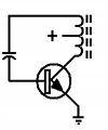
A blocking oscillator is a simple configuration of discrete electronic components which can produce a free-running signal, requiring only a resistor
Resistor
A linear resistor is a linear, passive two-terminal electrical component that implements electrical resistance as a circuit element.The current through a resistor is in direct proportion to the voltage across the resistor's terminals. Thus, the ratio of the voltage applied across a resistor's...
, a transformer
Transformer
A transformer is a device that transfers electrical energy from one circuit to another through inductively coupled conductors—the transformer's coils. A varying current in the first or primary winding creates a varying magnetic flux in the transformer's core and thus a varying magnetic field...
, and one amplifying element. The name is derived from the fact that the transistor
Transistor
A transistor is a semiconductor device used to amplify and switch electronic signals and power. It is composed of a semiconductor material with at least three terminals for connection to an external circuit. A voltage or current applied to one pair of the transistor's terminals changes the current...
(or tube) is cut-off or "blocked" for most of the duty-cycle, producing periodic pulses. The non-sinusoidal output is not suitable for use as a radio-frequency local oscillator, but it can serve as a timing generator, to power lights or LED
LEd
LEd is a TeX/LaTeX editing software working under Microsoft Windows. It is a freeware product....
s, and the simple tones are sufficient for applications such as alarms or a morse-code practice device. Some cameras use a blocking oscillator to strobe the flash prior to a shot to reduce the red-eye effect
Red-eye effect
The red-eye effect in photography is the common appearance of red pupils in color photographs of eyes. It occurs when using a photographic flash very close to the camera lens , in ambient low light. The effect appears in the eyes of humans and animals that have no tapetum lucidum, hence no...
.
When it comes to the components involved in this circuit, specific types of each component are needed to have it work to its full potential. The transformer is a vital component. For example, a pulse transformer creates rectangular pulses, which are characterized by fast rise and fall times with a flat top. There are a seemingly endless amount of combinations of voltages, transformers, capacitors, transistors and resistors that can be used to vary and model the circuit.
Due to the circuit's simplicity, it forms the basis for many of the learning projects in commercial electronic kits. The secondary winding of the transformer can be fed to a speaker, a lamp, or the windings of a relay. Instead of a resistor, a potentiometer
Potentiometer
A potentiometer , informally, a pot, is a three-terminal resistor with a sliding contact that forms an adjustable voltage divider. If only two terminals are used , it acts as a variable resistor or rheostat. Potentiometers are commonly used to control electrical devices such as volume controls on...
placed in parallel with the timing capacitor permits the frequency to be adjusted freely, but at low resistances the transistor can be overdriven, and possibly damaged. The output signal will jump in amplitude and be greatly distorted.
Circuit operation
The circuit works due to positive feedback through the transformer and involves two times -- the time Tclosed when the switch is closed, and the time Topen when the switch is open. The following abbreviations are used in the analysis:- t, time, a variable
- Tclosed: instant at the end of the closed cycle, beginning of open cycle. Also a measure of the time duration when the switch is closed.
- Topen: instant at the end of the open cycle, beginning of closed cycle. Same as T=0. Also a measure of the time duration when the switch is open.
- Vb, source voltage e.g. Vbattery
- Vp, voltage across the primary winding. An ideal switch will present supply voltage Vb across the primary, so in the ideal case Vp = Vb.
- Vs, voltage across the secondary winding
- Vz, fixed load voltage caused by e.g. by the reverse voltage of a Zener diodeZener diodeA Zener diode is a special kind of diode which allows current to flow in the forward direction in the same manner as an ideal diode, but will also permit it to flow in the reverse direction when the voltage is above a certain value known as the breakdown voltage, "Zener knee voltage" or "Zener...
or the forward voltage of a light-emitting diodeLight-emitting diodeA light-emitting diode is a semiconductor light source. LEDs are used as indicator lamps in many devices and are increasingly used for other lighting...
(LED). - Im, magnetizing current in the primary
- Ipeak,m, maximum or "peak" magnetizing current in the primary. Occurs immediately before Topen.
- Np, number of primary turns
- Ns, number of secondary turns
- N, the turns ratio defined as Ns/Np, . For an ideal transformer operating under ideal conditions, Is = Ip/N, Vs = N*Vp.
- Lp, primary (self-)inductance, a value determined by the number of primary turns Np squared, and an "inductance factor" AL. Self-inductance is often written as Lp = AL*Np2*10-9 henries.
- R, combined switch and primary resistance
- Up, energy stored in the flux of the magnetic field in the windings, as represented by the magnetizing current Im.
A more-detailed analysis would require the following:
- M = mutual inductance, its value determined by degree to which the magnetic field created by the primary couples to (is shared by) the secondary, and vice versa. coupling. Coupling is never perfect; there is always so-called primary and secondary "leakage flux". Usually calculated from short-circuit secondary and short-circuited primary measurements.
- Lp,leak = self-inductance that represents the magnetic field created by, and coupled to the primary windings only
- Ls,leak = self-inductance that represents the magnetic field created by, and coupled to the secondary windings only
- Cwindings = interwinding capacitance. Values exist for the primary turns only, the secondary turns only, and the primary-to-secondary windings. Usually combined into a single value.
Operation during Tclosed (time when the switch is closed)
When the switch (transistor, tube) closes it presents the source voltage Vb (e.g. battery voltage) across the transformer primary. The magnetizing current Im of the transformer is Im = Vprimary*t/Lp; here t (time) is a variable that starts at 0. This magnetizing current Im will "ride upon" any reflected secondary current Is that flows into a secondary load (e.g. into the control terminal of the switch; reflected secondary current in primary = Is/N). The changing primary current causes a changing magnetic field ("flux") through the transformer's windings; this changing field induces a (relatively) steady secondary voltage Vs = N*Vb. In some designs (as shown in the diagrams) the secondary voltage Vs adds to the source voltage Vb; in this case because the voltage across the primary (during the time the switch is closed) is approximately Vb, Vs = (N+1)*Vb. Alternately the switch may get some of its control voltage or current directly from Vb and the rest from the induced Vs. Thus the switch-control voltage or current is "in phase" meaning that it keeps the switch closed, and it (via the switch) maintains the source voltage across the primary.In the case when there is little or no primary resistance and little or no switch resistance, the increase of the magnetizing current Im is a "linear ramp" defined by the formula in the first paragraph. In the case when there is significant primary resistance or switch resistance or both (total resistance R, e.g. primary-coil resistance plus a resistor in the emitter, FET channel resitance), the Lp/R time constant causes the magnetizing current to be a rising curve with continually decreasing slope. In either case the magnetizing current Im will come to dominate the total primary (and switch) current Ip. Without a limiter it would increase forever. However, in the first case (low resistance), the switch will eventually be unable to "support" more current meaning that its effective resistance increases so much that the voltage drop across the switch equals the supply voltage; in this condition the switch is said to be "saturated" (e.g. this is determined by a transistor's gain hfe or "beta"). In the second case (e.g. primary and/or emitter resistance dominant) the (decreasing) slope of the current decreases to a point such that the induced voltage into the secondary is no longer adequate to keep the switch closed. In a third case, the magnetic "core" material saturates, meaning it cannot support further increases in its magnetic field; in this condition induction from primary to secondary fails. In all cases, the rate of rise of the primary magnetizing current (and hence the flux), or the rate-of-rise of the flux directly in the case of saturated core material, drops to zero (or close to zero). In the first two cases, although primary current continues to flow, it approaches a steady value equal to the supply voltage Vb divided by the total resistance(s) R in the primary circuit. In this current-limited condition the transformer's flux will be steady. Only changing flux causes induction of voltage into the secondary, so a steady flux represents a failure of induction. The secondary voltage drops to zero. The switch opens.
Operation during Topen (time when the switch is open)
Now that the switch has opened at Topen, the magnetizing current in the primary is Ipeak,m = Vp*Tclosed/Lp, and the energy Up is stored in this "magnetizing" field as created by Ipeak,m (energy Um = 1/2*Lp*Ipeak,m2). But now there is no primary voltage (Vb) to sustain further increases in the magnetic field, or even a steady-state field, the switch being opened and thereby removing the primary voltage. The magnetic field (flux) begins to collapse, and the collapse forces energy back into the circuit by inducing current and voltage into the primary turns, the secondary turns, or both. Induction into the primary will be via the primary turns through which all the flux passes (represented by primary inductance Lp); the collapsing flux creates primary voltage that forces current to continue to flow either out of the primary toward the (now-open) switch or into a primary load such as an LED or a Zener diode, etc. Induction into the secondary will be via the secondary turns through which the mutual (linked) flux passes; this induction causes voltage to appear at the secondary, and if this voltage is not blocked (e.g. by a diode or by the very high impedance of a FET gate), secondary current will flow into the secondary circuit (but in the opposite direction). In any case, if there are no components to absorb the current, the voltage at the switch rises very fast. Without a primary load or in the case of very limited secondary current the voltage will be limited only by the distributed capacitances of the windings (the so-called interwinding capacitance), and it can destroy the switch. When only interwinding capacitance and a tiny secondary load is present to absorb the energy, very high-frequency oscillations occur, and these "parasitic oscillations" represent a possible source of electromagnetic interferenceElectromagnetic interference
Electromagnetic interference is disturbance that affects an electrical circuit due to either electromagnetic induction or electromagnetic radiation emitted from an external source. The disturbance may interrupt, obstruct, or otherwise degrade or limit the effective performance of the circuit...
.
The potential of the secondary voltage now flips to negative in the following manner. The collapsing flux induces primary current to flow out of the primary toward the now-open switch i.e. to flow in the same direction it was flowing when the switch was closed. For current to flow out of the switch-end of the primary, the primary voltage at the switch end must be positive relative to its other end that is at the supply voltage Vb. But this represents a primary voltage opposite in polarity to what it was during the time when the switch was closed: during Tclosed, the switch-end of the primary was approximately zero and therefore negative relative to the supply end; now during Topen it has become positive relative to Vb.
Because of the transformer's "winding sense" (direction of its windings), the voltage that appears at the secondary must now be negative. A negative control voltage will maintain the switch (e.g. NPN bipolar transistor or N-channel FET)open, and this situation will persist until the energy of the collapsing flux has been absorbed (by something). When the absorber is in the primary circuit, e.g. a Zener diode (or LED) with voltage Vz connected "backwards" across the primary windings, the current waveshape is a triangle with the time topen determined by the formula Ip = Ipeak,m - Vz*Topen/Lp, here Ipeak,m being the primary current at the time the switch opens. When the absorber is a capacitor the voltage and current waveshapes are a 1/2 cycle sinewave, and if the absorber is a capacitor plus resistor the waveshapes are a 1/2 cycle damped sinewave.
When at last the energy discharge is complete, the control circuit becomes "unblocked". Control voltage (or current) to the switch is now free to "flow" into the control input and close the switch. This is easier to see when a capacitor "commutates" the control voltage or current; the ringing oscillation carries the control voltage or current from negative (switch open) through 0 to positive (switch closed).
Repetition rate 1/(Tclosed + Topen)
In the simplest case, the duration of the total cycle (Tclosed + Topen), and hence its repetition rate (the reciprocal of the cycle duration), is almost wholly dependent on the transformer's magnetizing inductance Lp, the supply voltage, and the load voltage Vz. When a capacitor and resistor are used to absorb the energy, the repetition rate is dependent on the R-C time-constant, or the L-C time constant when R is small or non-existant (L can be Lp, Ls or Lp,s).External links
- The blocking oscillator, web page by James B. Calvert. An elementary (no mathematics) and informative description of various blocking oscillator circuits, employing BJTs and TriodeTriodeA triode is an electronic amplification device having three active electrodes. The term most commonly applies to a vacuum tube with three elements: the filament or cathode, the grid, and the plate or anode. The triode vacuum tube was the first electronic amplification device...
s. - Circuit models to predict switching performance of nanosecond blocking oscillators, J. McDonald, IEEE Transactions on Circuits and Systems, 1964, Volume 11, Issue 4, 442- 448. A paper deriving some circuit models in order to predict the switching performance of BJT blocking oscillators.