
Water brake
Encyclopedia
>
Fluid coupling
A fluid coupling is a hydrodynamic device used to transmit rotating mechanical power. It has been used in automobile transmissions as an alternative to a mechanical clutch...
used to absorb mechanical energy and usually consists of a turbine
Turbine
A turbine is a rotary engine that extracts energy from a fluid flow and converts it into useful work.The simplest turbines have one moving part, a rotor assembly, which is a shaft or drum with blades attached. Moving fluid acts on the blades, or the blades react to the flow, so that they move and...
or propeller
Propeller
A propeller is a type of fan that transmits power by converting rotational motion into thrust. A pressure difference is produced between the forward and rear surfaces of the airfoil-shaped blade, and a fluid is accelerated behind the blade. Propeller dynamics can be modeled by both Bernoulli's...
mounted in an enclosure filled with water. As the turbine or propeller turns, mechanical energy is transferred to the water due to turbulence
Turbulence
In fluid dynamics, turbulence or turbulent flow is a flow regime characterized by chaotic and stochastic property changes. This includes low momentum diffusion, high momentum convection, and rapid variation of pressure and velocity in space and time...
and friction
Friction
Friction is the force resisting the relative motion of solid surfaces, fluid layers, and/or material elements sliding against each other. There are several types of friction:...
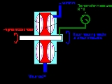
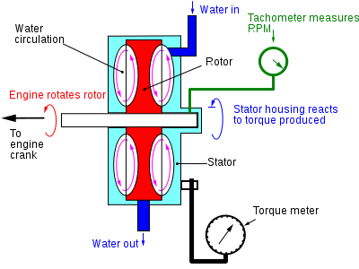
. . The shock caused by the acceleration of the water as it passes from pockets in the stator to the pockets in the spinning rotor requires energy. That energy heats the water due to the friction as the water moves thorough the water brake. Almost all of the horsepower of the system turning the rotor (usually an internal combustion engine) is converted into a temperature change of the water. A very small amount of energy is taken by the bearings and seals within the unit. Therefore, water must constantly move trough the device at a rate proportional to the horse power that is being absorbed. Water temperature exiting the unit must be kept under 120-160F to prevent scale formation and cavitation. The water enters in the center of the device and after passing through the pockets in the stator and rotor exits the outside of the housing though a controlled orifice. The amount of loading is dependant on the level of water inside the housing. Some water brakes vary the load by controlling the inlet water volume only and have a set outlet orifice size depending on the desired hp to be absorbed and some control both input and output orifices at the same time witch allows greater control over outlet water temperatures. The housing is vented to the outside to allow air to displace the water as the water level raises and lowers in the unit. Separate water pump force water into the unit and centrifugal force causes the water to exit.
The amount of torque that can be absorbed is defined by the equation T=KN^2D^2 where T = torque, N = RPM, D = the diameter of the rotor and K = a constant dependant on the size and shape and angle of the rotor/stator pockets.
Systems witch require the torque of the system under test to be measured typically use a strain gauge mounted on a torque arm that is attached to the housing perpendicular to the input shaft. The housing/stator is mounted on roller bearings and the rotor is mounted on roller bearings within the housing/stator so that it can turn independently of the rotor and frame. The strain gage connects the torque arm to the frame assembly and keeps the housing from spinning as housing tries to turn in the same direction of the turbine. (Newton’s third law).
The amount of resistance can be varied by changing the amount of water in the enclosure at any one time. This is accomplished though manual or electronically controlled water valves. The higher the water levels within the brake the greater the loading. Water brakes are commonly used on some forms of dynamometer
Dynamometer
A dynamometer or "dyno" for short, is a device for measuring force, moment of force , or power. For example, the power produced by an engine, motor or other rotating prime mover can be calculated by simultaneously measuring torque and rotational speed .A dynamometer can also be used to determine...
.
Hydrokinetic Construction (torque absorption)
The FroudeWilliam Froude
William Froude was an English engineer, hydrodynamicist and naval architect. He was the first to formulate reliable laws for the resistance that water offers to ships and for predicting their stability....
waterbrake is based on hydrokinetic construction or (torque absorption).
The machine consists of an impeller (rotor) which accelerates water outwards by its rotation. The water has its velocity changed by a stator which causes the water to be returned to the inner diameter of the rotor.
For given mass of water, this velocity change yields a corresponding momentum change – and the rate of change of momentum is proportional to a force. This force acting at some point within the rotor and stator is a distance from the shaft centerline, and a force multiplied by a distance produces torque.