

Reliability block diagram
Encyclopedia
A reliability block diagram (RBD) is a diagrammatic method for showing how component reliability
contributes to the success or failure of a complex system
. RBD is also known as a dependence diagram (DD).
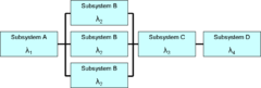 A RBD or DD is drawn as a series of blocks connected in parallel or series configuration. Each block represents a component of the system with a failure rate
. Parallel paths are redundant
, meaning that all of the parallel paths must fail for the parallel network to fail. By contrast, any failure along a series path causes the entire series path to fail.
A RBD may be drawn using switches in place of blocks, where a closed switch represents a working component and an open switch represents a failed component. If a path may be found through the network of switches from beginning to end, the system still works.
A RBD may be converted to a success tree by replacing series paths with AND gates
and parallel paths with OR gates
. A success tree may then be converted to a fault tree
by applying de Morgan's theorem.
Reliability engineering
Reliability engineering is an engineering field, that deals with the study, evaluation, and life-cycle management of reliability: the ability of a system or component to perform its required functions under stated conditions for a specified period of time. It is often measured as a probability of...
contributes to the success or failure of a complex system
System
System is a set of interacting or interdependent components forming an integrated whole....
. RBD is also known as a dependence diagram (DD).
Failure rate
Failure rate is the frequency with which an engineered system or component fails, expressed for example in failures per hour. It is often denoted by the Greek letter λ and is important in reliability engineering....
. Parallel paths are redundant
Redundancy (engineering)
In engineering, redundancy is the duplication of critical components or functions of a system with the intention of increasing reliability of the system, usually in the case of a backup or fail-safe....
, meaning that all of the parallel paths must fail for the parallel network to fail. By contrast, any failure along a series path causes the entire series path to fail.
A RBD may be drawn using switches in place of blocks, where a closed switch represents a working component and an open switch represents a failed component. If a path may be found through the network of switches from beginning to end, the system still works.
A RBD may be converted to a success tree by replacing series paths with AND gates
AND gate
The AND gate is a basic digital logic gate that implements logical conjunction - it behaves according to the truth table to the right. A HIGH output results only if both the inputs to the AND gate are HIGH . If neither or only one input to the AND gate is HIGH, a LOW output results...
and parallel paths with OR gates
OR gate
The OR gate is a digital logic gate that implements logical disjunction - it behaves according to the truth table to the right. A HIGH output results if one or both the inputs to the gate are HIGH . If neither input is HIGH, a LOW output results...
. A success tree may then be converted to a fault tree
Fault tree analysis
Fault tree analysis is a top down, deductive failure analysis in which an undesired state of a system is analyzed using boolean logic to combine a series of lower-level events...
by applying de Morgan's theorem.
External links
- http://www.reliability-block-diagram.com/ (commercial website)
- http://www.reliabilityeducation.com/rbd.pdf (commercial website)