
Multiview orthographic projection
Encyclopedia

The views are positioned relative to each other according to either of two schemes: first-angle or third-angle projection. In each, the appearances of views may be thought of as being projected onto planes that form a 6-sided box around the object.
Quadrants in descriptive geometry
Gaspard Monge
Gaspard Monge, Comte de Péluse was a French mathematician, revolutionary, and was inventor of descriptive geometry. During the French Revolution, he was involved in the complete reorganization of the educational system, founding the École Polytechnique...
's descriptive geometry
Descriptive geometry
Descriptive geometry is the branch of geometry which allows the representation of three-dimensional objects in two dimensions, by using a specific set of procedures. The resulting techniques are important for engineering, architecture, design and in art...
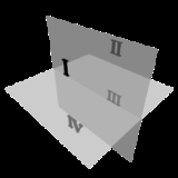
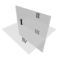
. Monge defined a reference system of two viewing planes, horizontal H ("ground") and vertical V ("backdrop"). These two planes intersect to partition 3D space into 4 quadrants, which he labeled:
- I: above H, in front of V
- II: above H, behind V
- III: below H, behind V
- IV: below H, in front of V
These quadrant labels are the same as used in 2D planar geometry, as seen from infinitely far to the "left", taking H and V to be the X-axis and Y-axis, respectively.
The 3D object of interest is then placed into either quadrant I or III (equivalently, the position of the intersection line between the two planes is shifted), obtaining first- and third-angle projections, respectively. Quadrants II and IV are also mathematically valid, but their use would result in one view "true" and the other view "flipped" by 180° through its vertical centerline, which is too confusing for technical drawings.
Monge's original formulation uses two planes only, and obtains the top and front views only. The addition of a third plane to show a side view (either left or right) is a modern extension. The terminology of quadrant is a mild anachronism, as a modern orthographic projection with three views corresponds more precisely to an octant of 3D space.
First-angle projection
In first-angle projection, the object is conceptually located in quadrant I, i.e. it floats above and before the viewing planes, the planes are opaque, and each view is pushed through the object onto the plane furthest from it. (Mnemonic: an "actor on a stage".) Extending to the 6-sided box, each view of the object is projected in the direction (sense) of sight of the object, onto the (opaque) interior walls of the box; that is, each view of the object is drawn on the opposite side of the box. A two-dimensional representation of the object is then created by "unfolding" the box, to view all of the interior walls. This produces two planPlan
A plan is typically any diagram or list of steps with timing and resources, used to achieve an objective. See also strategy. It is commonly understood as a temporal set of intended actions, through which one expects to achieve a goal...
s and four elevation
Elevation
The elevation of a geographic location is its height above a fixed reference point, most commonly a reference geoid, a mathematical model of the Earth's sea level as an equipotential gravitational surface ....
s. A simpler way to visualize this is to place the
object on top of an upside-down bowl. Sliding the object down the right edge of the bowl reveals the right side view.
Third-angle projection
Here is the construction of third angle projections of the same object as above. Note that the individual views are the same, just arranged differently.
Additional information
First-angle projection is as if the object were sitting on the paper and, fromthe "face" (front) view, it is rolled to the right to show the left side or rolled up to show its bottom. It is standard throughout Europe (excluding the UK) and Asia. First-angle projection used to be common in the UK, and may still be seen on historical design drawings, but has now fallen into disuse in favour of third-angle projection.
Third-angle is as if the object were a box to be unfolded. If we unfold the box so that the front view is in the center of the two arms, then the top view is above it, the bottom view is below it, the left view is to the left, and the right view is to the right. It is standard in the United Kingdom (BS 8888:2006 specifies it as the default projection system), USA (ASME
American Society of Mechanical Engineers
The American Society of Mechanical Engineers is a professional body, specifically an engineering society, focused on mechanical engineering....
Y14.3-2003 specifies it as the default projection system), Canada, and Australia.
Both first-angle and third-angle projections result in the same 6 views; the difference between them is the arrangement of these views around the box.
A great deal of confusion has ensued in drafting rooms and engineering departments when drawings are transferred from one convention to another. On engineering drawing
Engineering drawing
An engineering drawing, a type of technical drawing, is used to fully and clearly define requirements for engineered items.Engineering drawing produces engineering drawings . More than just the drawing of pictures, it is also a language—a graphical language that communicates ideas and information...
s, the projection angle is denoted by an international symbol consisting of a truncated cone
Cone (geometry)
A cone is an n-dimensional geometric shape that tapers smoothly from a base to a point called the apex or vertex. Formally, it is the solid figure formed by the locus of all straight line segments that join the apex to the base...
, respectively for first-angle (FR) and third-angle (US):
The 3D interpretation of the symbol can be deduced by envisioning a solid truncated cone, standing upright with its large end on the floor and the small end upward. The top view is therefore two concentric circles ("donut"). In particular, the fact that the inner circle is drawn with a solid line instead of dashed disambiguates this view as the top view, not the bottom view.
- In first-angle projection, the "top" view is pushed down to the floor, and the "front" view is pushed back to the rear wall; the intersection line between these two planes is therefore closest to the large end of the cone, hence the first-angle symbol shows the cone with its large end open toward the donut.
- In third-angle projection, the "top" view is pulled up to the ceiling, and the "front" view is pulled forward to the front wall; the intersection line between the two planes is thus closest to the small end of the cone, hence the third-angle symbol shows the cone with its large end away from the donut.
Multiviews without rotation
Orthographic multiview projection is derived from the principles of descriptive geometryDescriptive geometry
Descriptive geometry is the branch of geometry which allows the representation of three-dimensional objects in two dimensions, by using a specific set of procedures. The resulting techniques are important for engineering, architecture, design and in art...
and may produce an image of a specified, imaginary object as viewed from any direction of space. Orthographic projection is distinguished by parallel projectors emanating from all points of the imaged object and which intersect a plane of projection at right angles. Above, a technique is described that obtains varying views by projecting images after the object is rotated to a desired position.
Descriptive geometry customarily relies on obtaining various views by imagining an object to be stationary, and changing the direction of projection (viewing) in order to obtain the desired view.
See Figure 1. Using the rotation technique above, note that no orthographic view is available looking perpendicularly at any of the inclined surfaces. Suppose a technician desired such a view to, say, look through a hole to be drilled perpendicularly to the surface. Such a view might be desired for calculating clearances or for dimensioning purposes. To obtain this view without multiple rotations requires the principles of Descriptive Geometry. The steps below describe the use of these principles in third angle projection.
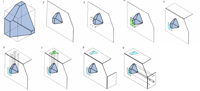
- Fig.1: Pictorial of imaginary object that the technician wishes to image.
- Fig.2: The object is imagined behind a vertical plane of projection. The angled corner of the plane of projection is addressed later.
- Fig.3: Projectors emanate parallel from all points of the object, perpendicular to the plane of projection.
- Fig.4: An image is created thereby.
- Fig.5: A second, horizontal plane of projection is added, perpendicular to the first.
- Fig.6: Projectors emanate parallel from all points of the object perpendicular to the second plane of projection.
- Fig.7: An image is created thereby.
- Fig.8: A third plane of projection is added, perpendicular to the previous two.
- Fig.9: Projectors emanate parallel from all points of the object perpendicular to the third plane of projection.
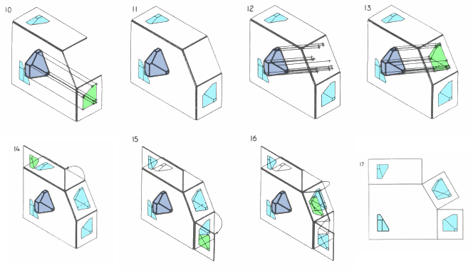
- Fig.10: An image is created thereby.
- Fig.11: A fourth plane of projection is added parallel to the chosen inclined surface, and per force, perpendicular to the first (Frontal) plane of projection.
- Fig.12: Projectors emanate parallel from all points of the object perpendicularly from the inclined surface, and per force, perpendicular to the fourth (Auxiliary) plane of projection.
- Fig.13: An image is created thereby.
- Fig.14-16: The various planes of projection are unfolded to be planar with the Frontal plane of projection.
- Fig.17: The final appearance of an orthographic multiview projection and which includes an "Auxiliary view" showing the true shape of an inclined surface.
Section
A section, or cross-section, is a view of a 3-dimensional object from the position of a plane through the object.A cross section is a common method of depicting the internal arrangement of a 3-dimensional object in two dimensions. It is often used in technical drawing
Technical drawing
Technical drawing, also known as drafting or draughting, is the act and discipline of composing plans that visually communicate how something functions or has to be constructed.Drafting is the language of industry....
and is traditionally crosshatched. The style of crosshatching indicates the type of material the section passes through.
With computed axial tomography, computers construct cross-sections from x-ray
X-ray
X-radiation is a form of electromagnetic radiation. X-rays have a wavelength in the range of 0.01 to 10 nanometers, corresponding to frequencies in the range 30 petahertz to 30 exahertz and energies in the range 120 eV to 120 keV. They are shorter in wavelength than UV rays and longer than gamma...
data.
Elevation

An elevation is a common method of depicting the external configuration and detailing of a 3-dimensional object in two dimensions. Building façades are shown as elevations in architectural drawing
Architectural drawing
An architectural drawing or architect's drawing is a technical drawing of a building that falls within the definition of architecture...
s and technical drawing
Technical drawing
Technical drawing, also known as drafting or draughting, is the act and discipline of composing plans that visually communicate how something functions or has to be constructed.Drafting is the language of industry....
s.
Elevations are the most common orthographic projection for conveying the appearance of a building from the exterior. Perspectives are also commonly used for this purpose. A building elevation is typically labeled in relation to the compass direction it faces; the direction from which a person views it. E.g. the North Elevation of a building is the side that most closely faces true north on the compass.
Interior elevations are used to show detailing such as millwork
Millwork
Millwork is any woodmill-produced building construction interior finish components such as doors, window casing, baseboard, mantels, and crown molding....
and trim configurations.
In the building industry elevations are a non-perspective view of the structure. These are drawn to scale so that measurements can be taken for any aspect necessary. Drawing sets include front, rear and both side elevations. The elevations specify the composition of the different facades of the building, including ridge heights, the positioning of the final fall of the land, exterior finishes, roof pitches and other architectural details.
Developed Elevation
A developed elevation is a variant of a regular elevation view in which several adjacent non-parallel sides may be shown together, as if they have been unfolded. For example, the north and west views may be shown side-by-side, sharing an edge, even though this does not represent a proper orthographic projection.Plan
A plan is a view of a 3-dimensional object from the position of a horizontal plane through, above, or below the object. In such views, the portion of the object in front of the plane is omitted to reveal what lies beyond. In the case of a floor plan, the roof and upper portion of the walls may be omitted. Elevations, top (roof) plans, and bottom plans are orthographic projections, but they are not sections as their viewing plane is outside of the object.A plan is a common method of depicting the internal arrangement of a 3-dimensional object in two dimensions. It is often used in technical drawing
Technical drawing
Technical drawing, also known as drafting or draughting, is the act and discipline of composing plans that visually communicate how something functions or has to be constructed.Drafting is the language of industry....
and is traditionally cross-hatched. The style of crosshatching indicates the type of material the section passes through.
Auxiliary view
An auxiliary view is a view taken from an angle that is not one of the primary views. An auxiliary view is a view at an angle used to give deeper insight into the actual shape of the object. An auxiliary view is used to show a slanted surface in true size and shape. This is accomplished by providing a view that is perpendicular to the slanted surface.See also
- Architectural drawingArchitectural drawingAn architectural drawing or architect's drawing is a technical drawing of a building that falls within the definition of architecture...
- Cross section (geometry)Cross section (geometry)In geometry, a cross-section is the intersection of a figure in 2-dimensional space with a line, or of a body in 3-dimensional space with a plane, etc...
- Engineering drawingEngineering drawingAn engineering drawing, a type of technical drawing, is used to fully and clearly define requirements for engineered items.Engineering drawing produces engineering drawings . More than just the drawing of pictures, it is also a language—a graphical language that communicates ideas and information...
- Graphical projectionGraphical projectionGraphical projection is a protocol by which an image of a three-dimensional object is projected onto a planar surface without the aid of mathematical calculation, used in technical drawing.- Overview :...
- Plans (drawings)Plans (drawings)Plans are a set of drawings or two-dimensional diagrams used to describe a place or object, or to communicate building or fabrication instructions. Usually plans are drawn or printed on paper, but they can take the form of a digital file.- Overview :...
External links
- Educational website describing the principles of first and third angle projection — University of LimerickUniversity of LimerickThe University of Limerick is a university in Ireland near the city of Limerick on the island's west coast. It was established in 1972 as the National Institute for Higher Education, Limerick and became a university by statute in 1989 in accordance with the University of Limerick Act 1989...
- Educational website describing the principles of first and third angle projection
- Images tagged "Elevation" on Flickr.com