

IBM 1620
Encyclopedia
IBM 1710
The IBM 1710 was a process control system that IBM introduced in March 1961. It used either a 1620 I or a 1620 II Computer and specialized I/O devices .The IBM 1620 used in the 1710 system was modified in several ways, the most obvious was the addition of a very...
and IBM 1720
IBM 1720
The IBM 1720 was a pilot project to create a real-time process control computer based on the IBM 1620 Model I.Only three 1720 systems were ever built: one for the Amoco oil refinery in Whiting, Indiana; one for the Socal oil refinery in El Segundo, California; and one for E. I. du Pont in...
Industrial Process Control Systems (making it the first digital computer considered reliable enough for real-time
Real-time computing
In computer science, real-time computing , or reactive computing, is the study of hardware and software systems that are subject to a "real-time constraint"— e.g. operational deadlines from event to system response. Real-time programs must guarantee response within strict time constraints...
process control
Process control
Process control is a statistics and engineering discipline that deals with architectures, mechanisms and algorithms for maintaining the output of a specific process within a desired range...
of factory equipment).
Being variable word length decimal, as opposed to fixed-word-length pure binary, made it an especially attractive first computer to learn on — and hundreds of thousands of students had their first experiences with a computer on the IBM 1620.
Core memory cycle times were 20 microseconds for the Model I
IBM 1620 Model I
The IBM 1620 Model I was the original implementation of the IBM 1620 scientific computer, introduced in 1959.This unit was produced as inexpensively as IBM could make it, in order to keep the price low...
, 10 microseconds for the Model II
IBM 1620 Model II
The IBM 1620 Model II was a vastly improved implementation, compared to the original Model I, of the IBM 1620 scientific computer architecture....
(about a thousand times slower than typical computer main memory in 2006).
Many in the user community recall the 1620 being referred to as CADET, jokingly meaning "Can't Add, Doesn't Even Try", referring to the use of addition tables in memory rather than dedicated addition circuitry.
For an explanation of all three known interpretations of the machine's code name see the section on the machine's development history.
The 1620's architecture
It was a variable "word" length decimal (BCDBinary-coded decimal
In computing and electronic systems, binary-coded decimal is a digital encoding method for numbers using decimal notation, with each decimal digit represented by its own binary sequence. In BCD, a numeral is usually represented by four bits which, in general, represent the decimal range 0 through 9...
) computer with a memory that could hold anything from 20,000 to 60,000 decimal digits increasing in 20,000 decimal digit increments. (While the 5-digit addresses could have addressed 100,000 decimal digits, no machine larger than 60,000 decimal digits was ever built.)
Memory was accessed two decimal digits at the same time (even-odd digit pair for numeric data or one alphameric
Alphanumeric
Alphanumeric is a combination of alphabetic and numeric characters, and is used to describe the collection of Latin letters and Arabic digits or a text constructed from this collection. There are either 36 or 62 alphanumeric characters. The alphanumeric character set consists of the numbers 0 to...
character for text data). Each decimal digit was 6 bits, composed of an odd parity Check bit, a Flag bit, and four BCD bits for the value of the digit in the following format:
C F 8 4 2 1
The Flag bit had several uses:
- In the least significant digit it was set to indicate a negative number (signed magnitude).
- It was set to mark the most significant digit of a number (wordmarkWordmark (computer hardware)In computer hardware, a wordmark is a bit in each memory location on some variable word length computers used to mark the end of a word. Sometimes the actual bit used as a wordmark on a given machine is not called wordmark, but has a different name ....
). - In the least significant digit of 5-digit addresses it was set for indirect addressing (an option on the 1620 IIBM 1620 Model IThe IBM 1620 Model I was the original implementation of the IBM 1620 scientific computer, introduced in 1959.This unit was produced as inexpensively as IBM could make it, in order to keep the price low...
, standard on the 1620 II). Multi-level indirection could be used (you could even put the machine in an infinite indirect addressing loop). - In the middle 3 digits of 5-digit addresses (on the 1620 IIIBM 1620 Model IIThe IBM 1620 Model II was a vastly improved implementation, compared to the original Model I, of the IBM 1620 scientific computer architecture....
) they were set to select one of 7 index registerIndex registerAn index registerCommonly known as a B-line in early British computers. in a computer's CPU is a processor register used for modifying operand addresses during the run of a program, typically for doing vector/array operations...
s.
In addition to the valid BCD digit values there were three special digit values (these could NOT be used in calculations):
C F 8 4 2 1
1 0 1 0 - Record Mark (right most end of record)
1 1 0 0 - Numeric Blank (blank for punched card output formatting)
1 1 1 1 - Group Mark (right most end of a group of records for disk I/O)
Instructions
Instruction set
An instruction set, or instruction set architecture , is the part of the computer architecture related to programming, including the native data types, instructions, registers, addressing modes, memory architecture, interrupt and exception handling, and external I/O...
were fixed length (12 decimal digits), consisting of a 2-digit "op code
Opcode
In computer science engineering, an opcode is the portion of a machine language instruction that specifies the operation to be performed. Their specification and format are laid out in the instruction set architecture of the processor in question...
", a 5-digit "P Address" (usually the destination address), and a 5-digit "Q Address" (usually the source address or the source immediate value). Some instructions, such as the B (branch) instruction, only used the P Address, and later smart assemblers included a "B7" instruction that generated an 7-digit branch instruction (op code, P address, and one extra digit because the next instruction had to start on an even-numbered digit).
Fixed-point
Fixed-point arithmetic
In computing, a fixed-point number representation is a real data type for a number that has a fixed number of digits after the radix point...
data "words" could be any size from two decimal digits up to all of memory not used for other purposes.
Floating-point
Floating point
In computing, floating point describes a method of representing real numbers in a way that can support a wide range of values. Numbers are, in general, represented approximately to a fixed number of significant digits and scaled using an exponent. The base for the scaling is normally 2, 10 or 16...
data "words" (using the hardware floating point
Floating point
In computing, floating point describes a method of representing real numbers in a way that can support a wide range of values. Numbers are, in general, represented approximately to a fixed number of significant digits and scaled using an exponent. The base for the scaling is normally 2, 10 or 16...
option) could be any size from 4 decimal digits up to 102 decimal digits (2 to 100 digits for the mantissa
Significand
The significand is part of a floating-point number, consisting of its significant digits. Depending on the interpretation of the exponent, the significand may represent an integer or a fraction.-Examples:...
and 2 digits for the exponent).
The machine had no programmer-accessible registers: all operations were memory to memory (including the index register
Index register
An index registerCommonly known as a B-line in early British computers. in a computer's CPU is a processor register used for modifying operand addresses during the run of a program, typically for doing vector/array operations...
s of the 1620 II
IBM 1620 Model II
The IBM 1620 Model II was a vastly improved implementation, compared to the original Model I, of the IBM 1620 scientific computer architecture....
).
Character and Op codes
The table below lists Alphameric mode Characters (and Op codes).| BCD Character | Typewriter | Printer | Tape | Card | Core | MNEMONIC & Operation | Definition & Notes | ||||
|---|---|---|---|---|---|---|---|---|---|---|---|
| In | Out | Out | In | Out | In | Out | Even | Odd | |||
| Blank | C | C | |||||||||
| invalid | Ж ❚ | 1 | FADD Floating Add | Optional special feature. | |||||||
| invalid | Ж ❚ | 2 | FSUB Floating Subtract | Optional special feature. | |||||||
| . | . | . | . | X0 8 21 | X0 8 21 | 12-3-8 12-1-2-8 |
12-3-8 | 21 | FMUL Floating Multiply | Optional special feature. | |
| ) | ) | ) | ) | X0C84 | X0C84 | 12-4-8 | 12-4-8 | 4 | |||
| invalid | Ж ❚ | 4 1 | FSL Floating Shift Left | Optional special feature. | |||||||
| invalid | Ж ❚ | 42 | TFL Transmit Floating | Optional special feature. | |||||||
| invalid | Ж ❚ | 421 | BTFL Branch and Transmit Floating | Optional special feature. | |||||||
| invalid | Ж ❚ | 8 | FSR Floating Shift Right | Optional special feature. | |||||||
| invalid | Ж ❚ | 8 1 | FDIV Floating Divide | Optional special feature. | |||||||
| + | + | + | + | X0C | X0C | 12 | 12 | 1 | |||
| invalid | Ж ❚ | 1 | 1 | AM Add Immediate | |||||||
| invalid | Ж ❚ | 1 | 2 | SM Subtract Immediate | |||||||
| $ | $ | $ | $ | X C8 21 | X C8 21 | 11-3-8 11-1-2-8 |
11-3-8 | 1 | 21 | MM Multiply Immediate | |
| * | * | * | * | X 84 | X 84 | 11-4-8 | 11-4-8 | 1 | 4 | CM Compare Immediate | |
| invalid | Ж ❚ | 1 | 4 1 | TDM Transmit Digit Immediate | |||||||
| invalid | Ж ❚ | 1 | 42 | TFM Transmit Field Immediate | |||||||
| invalid | Ж ❚ | 1 | 421 | BTM Branch and Transmit Immediate | |||||||
| invalid | Ж ❚ | 1 | 8 | LDM Load Dividend Immediate | Optional special feature (Model I). Standard (Model II). |
||||||
| invalid | Ж ❚ | 1 | 8 1 | DM Divide Immediate | Optional special feature (Model I). Standard (Model II). |
||||||
| - | - | - | - | X | X | 11 | 11 | 2 | |||
| / | / | / | / | 0C 1 | 0C 1 | 0-1 | 0-1 | 2 | 1 | A Add | |
| invalid | Ж ❚ | 2 | 2 | S Subtract | |||||||
| , | , | , | , | 0C8 21 | 0C8 21 | 0-3-8 0-1-2-8 |
0-3-8 | 2 | 21 | M Multiply | |
| ( | ( | ( | ( | 0 84 | 0 84 | 0-4-8 | 0-4-8 | 2 | 4 | C Compare | |
| invalid | Ж ❚ | 2 | 4 1 | TD Transmit Digit | |||||||
| invalid | Ж ❚ | 2 | 42 | TF Transmit Field | |||||||
| invalid | Ж ❚ | 2 | 421 | BT Branch and Transmit | |||||||
| invalid | Ж ❚ | 2 | 8 | LD Load Dividend | Optional special feature (Model I). Standard (Model II). |
||||||
| invalid | Ж ❚ | 2 | 8 1 | D Divide | Optional special feature (Model I). Standard (Model II). |
||||||
| invalid | Ж ❚ | 21 | TRNM Transmit Record No RM | (Model II) | |||||||
| invalid | Ж ❚ | 21 | 1 | TR Transmit Record | |||||||
| invalid | Ж ❚ | 21 | 2 | SF Set Flag | |||||||
| = | = | = | = | 8 21 | 8 21 | 3-8 1-2-8 |
3-8 | 21 | 21 | CF Clear Flag | |
| @ | @ | @ | @ | C84 | C84 | 4-8 | 4-8 | 21 | 4 | K Control (I/O device) | |
| invalid | Ж ❚ | 21 | 4 1 | DN Dump Numeric | |||||||
| invalid | Ж ❚ | 21 | 42 | RN Read Numeric | |||||||
| invalid | Ж ❚ | 21 | 421 | RA Read Alphameric | |||||||
| invalid | Ж ❚ | 21 | 8 | WN Write Numeric | |||||||
| invalid | Ж ❚ | 21 | 8 1 | WA Write Alphameric | |||||||
| A | A | A | A | X0 1 | X0 1 | 12-1 | 12-1 | 4 | 1 | NOP No Operation | |
| B | B | B | B | X0 2 | X0 2 | 12-2 | 12-2 | 4 | 2 | BB Branch Back | |
| C | C | C | C | X0C 21 | X0C 21 | 12-3 12-1-2 |
12-3 | 4 | 21 | BD Branch On Digit | |
| D | D | D | D | X0 4 | X0 4 | 12-4 | 12-4 | 4 | 4 | BNF Branch No Flag | |
| E | E | E | E | X0C 4 1 | X0C 4 1 | 12-5 12-1-4 |
12-5 | 4 | 4 1 | BNR Branch No Record Mark | |
| F | F | F | F | X0C 42 | X0C 42 | 12-6 12-2-4 |
12-6 | 4 | 42 | BI Branch Indicator | |
| UMK Unmask MK Mask |
1710 interrupt feature. Modifiers in Q field. | ||||||||||
| G | G | G | G | X0 421 | X0 421 | 12-7 12-1-2-4 |
12-7 | 4 | 421 | BNI Branch No Indicator | |
| BO Branch Out BOLD Branch Out and Load |
1710 interrupt feature. Modifiers in Q field. | ||||||||||
| H | H | H | H | X0 8 | X0 8 | 12-8 | 12-8 | 4 | 8 | H Halt | |
| I | I | I | I | X0C8 1 | X0C8 1 | 12-9 12-1-8 |
12-9 | 4 | 8 1 | B Branch | |
| -0 | N/A | - | - | N/A | X | 11-0 | 11-0 | 4 1 | |||
| J -1 |
J | J | J | X C 1 | X C 1 | 11-1 | 11-1 | 4 1 | 1 | ||
| K -2 |
K | K | K | X C 2 | X C 2 | 11-2 | 11-2 | 4 1 | 2 | ||
| L -3 |
L | L | L | X 21 | X 21 | 11-3 11-1-2 |
11-3 | 4 1 | 21 | ||
| M -4 |
M | M | M | X C 4 | X C 4 | 11-4 | 11-4 | 4 1 | 4 | ||
| N -5 |
N | N | N | X 4 1 | X 4 1 | 11-5 11-1-4 |
11-5 | 4 1 | 4 1 | BNG Branch No Group Mark | Optional special feature. |
| O -6 |
O | O | O | X 42 | X 42 | 11-6 11-2-4 |
11-6 | 4 1 | 42 | ||
| P -7 |
P | P | P | X C 421 | X C 421 | 11-7 11-1-2-4 |
11-7 | 4 1 | 421 | ||
| Q -8 |
Q | Q | Q | X C8 | X C8 | 11-8 | 11-8 | 4 1 | 8 | ||
| R -9 |
R | R | R | X 8 1 | X 8 1 | 11-9 11-1-8 |
11-9 | 4 1 | 8 1 | ||
| invalid | Ж ❚ | 42 | BS Branch and Select | (Model II) | |||||||
| invalid | Ж ❚ | 42 | 1 | BX Branch and Modify Index Register | Optional special feature (Model II). | ||||||
| S | S | S | S | 0C 2 | 0C 2 | 0-2 | 0-2 | 42 | 2 | BXM Branch and Modify Index Register Immediate | Optional special feature (Model II). |
| T | T | T | T | 0 21 | 0 21 | 0-3 0-1-2 |
0-3 | 42 | 21 | BCX Branch Conditionally and Modify Index Register | Optional special feature (Model II). |
| U | U | U | U | 0C 4 | 0C 4 | 0-4 | 0-4 | 42 | 4 | BCXM Branch Conditionally and Modify Index Register Immediate | Optional special feature (Model II). |
| V | V | V | V | 0 4 1 | 0 4 1 | 0-5 0-1-4 |
0-5 | 42 | 4 1 | BLX Branch and Load Index Register | Optional special feature (Model II). |
| W | W | W | W | 0 42 | 0 42 | 0-6 0-2-4 |
0-6 | 42 | 42 | BLXM Branch and Load Index Register Immediate | Optional special feature (Model II). |
| X | X | X | X | 0C 421 | 0C 421 | 0-7 0-1-2-4 |
0-7 | 42 | 421 | BSX Branch and Store Index Register | Optional special feature (Model II). |
| Y | Y | Y | Y | 0C8 | 0C8 | 0-8 | 0-8 | 42 | 8 | ||
| Z | Z | Z | Z | 0 8 1 | 0 8 1 | 0-9 0-1-8 |
0-9 | 42 | 8 1 | ||
| 0 | 0 | 0 | 0 | 0 | 0 | 0 12-0 |
0 | 421 | MA Move Address | Optional special feature (Model II). | |
| 1 | 1 | 1 | 1 | 1 | 1 | 1 | 1 | 421 | 1 | MF Move Flag | Optional special feature (Model I). Standard (Model II). |
| 2 | 2 | 2 | 2 | 2 | 2 | 2 | 2 | 421 | 2 | TNS Transmit Numeric Strip | Optional special feature (Model I). Standard (Model II). |
| 3 | 3 | 3 | 3 | C 21 | C 21 | 3 | 3 | 421 | 21 | TNF Transmit Numeric Fill | Optional special feature (Model I). Standard (Model II). |
| 4 | 4 | 4 | 4 | 4 | 4 | 4 | 4 | 421 | 4 | ||
| 5 | 5 | 5 | 5 | C 4 1 | C 4 1 | 5 | 5 | 421 | 4 1 | ||
| 6 | 6 | 6 | 6 | C 42 | C 42 | 6 | 6 | 421 | 42 | ||
| 7 | 7 | 7 | 7 | 421 | 421 | 7 | 7 | 421 | 421 | ||
| 8 | 8 | 8 | 8 | 8 | 8 | 8 | 8 | 421 | 8 | ||
| 9 | 9 | 9 | 9 | C8 1 | C8 1 | 9 | 9 | 421 | 8 1 | ||
| invalid | Ж ❚ | 8 | 4 | SA Select Address SACO Select Address, Contact Operate SAOS Select Analog Output Signal |
1710 feature. Modifiers in Q field | ||||||
| invalid | Ж ❚ | 8 | 42 | SLTA Select TAS SLAR Select ADC Register SLTC Select Real-Time Clock SLIC Select Input Channel SLCB Select Contact Block SLME Select Manual Entry |
1710 feature. Modifiers in Q field | ||||||
| invalid | Ж ❚ | 8 | F 42 | RNIC Read Numeric Input Channel | 1710 feature. Modifiers in Q field | ||||||
| invalid | Ж ❚ | 8 | F 421 | RAIC Read Alphameric Input Channel | 1710 feature. Modifiers in Q field | ||||||
| invalid | Ж ❚ | 8 | 8 | WNOC Write Numeric Output Channel | 1710 feature. Modifiers in Q field | ||||||
| invalid | Ж ❚ | 8 | 8 1 | WAOC Write Alphameric Output Channel | 1710 feature. Modifiers in Q field | ||||||
| invalid | Ж ❚ | 8 1 | BBT Branch on Bit | Optional special feature (Model II). | |||||||
| invalid | Ж ❚ | 8 1 | 1 | BMK Branch on Mask | Optional special feature (Model II). | ||||||
| invalid | Ж ❚ | 8 1 | 2 | ORF OR to Field | Optional special feature (Model II). | ||||||
| invalid | Ж ❚ | 8 1 | 21 | ANDF AND to Field | Optional special feature (Model II). | ||||||
| invalid | Ж ❚ | 8 1 | 4 | CPLF Complement Octal Field | Optional special feature (Model II). | ||||||
| invalid | Ж ❚ | 8 1 | 4 1 | EORF Exclusive OR to Field | Optional special feature (Model II). | ||||||
| invalid | Ж ❚ | 8 1 | 42 | OTD Octal to Decimal Conversion | Optional special feature (Model II). | ||||||
| invalid | Ж ❚ | 8 1 | 421 | DTO Decimal to Octal Conversion | Optional special feature (Model II). | ||||||
| RM | ‡ | (Stop) | (Stop) | 0 8 2 | E (Stop) |
0-2-8 | 0-2-8 | 8 2 | Record Mark | ||
| GM | | (Stop) | (Stop) | 0 8421 | E (Stop) |
0-7-8 | 1-2-4-8 | 8421 | Group Mark | ||
The table below lists Numeric mode Characters.
| Character | Typewriter | Printer | Tape | Card | Core | Definition & Notes | ||||
|---|---|---|---|---|---|---|---|---|---|---|
| In | Out | Out | Dump | In | Out | In | Out | |||
| Blank | 0 | 0 | 0 | C | 0 | 0 | C | |||
| 0 | 0 | 0 | 0 | 0 | 0 | 0 | 0 12-0 12 |
0 | C | |
| 1 | 1 | 1 | 1 | 1 | 1 | 1 | 1 12-1 |
1 | 1 | |
| 2 | 2 | 2 | 2 | 2 | 2 | 2 | 2 12-1 |
2 | 2 | |
| 3 | 3 | 3 | 3 | 3 | C 21 | C 21 | 3 12-3 1-2 12-1-2 |
3 | C 21 | |
| 4 | 4 | 4 | 4 | 4 | 4 | 4 | 4 12-4 |
4 | 4 | |
| 5 | 5 | 5 | 5 | 5 | C 4 1 | C 4 1 | 5 12-5 1-4 12-1-4 |
5 | C 4 1 | |
| 6 | 6 | 6 | 6 | 6 | C 42 | C 42 | 6 12-6 2-4 12-2-4 |
6 | C 42 | |
| 7 | 7 | 7 | 7 | 7 | 421 | 421 | 7 12-7 1-2-4 12-1-2-4 |
7 | 421 | |
| 8 | 8 | 8 | 8 | 8 | 8 | 8 | 8 12-8 |
8 | 8 | |
| 9 | 9 | 9 | 9 | 9 | C8 1 | C8 1 | 9 12-9 1-8 12-1-8 |
9 | C 8 1 | |
| -0 | 0 | 0 | - | - | X X0C |
X | 11-0 | 11-0 | F | |
| -1 | 1 | 1 | J | J | X C 1 | X C 1 | 11-1 | 11-1 | CF 1 | |
| -2 | 2 | 2 | K | K | X C 2 | X C 2 | 11-2 | 11-2 | CF 2 | |
| -3 | 3 | 3 | L | L | X 21 | X 21 | 11-3 11-1-2 |
11-3 | F 21 | |
| -4 | 4 | 4 | M | M | X C 4 | X C 4 | 11-4 | 11-4 | CF 4 | |
| -5 | 5 | 5 | N | N | X 4 1 | X 4 1 | 11-5 11-1-4 |
11-5 | F 4 1 | |
| -6 | 6 | 6 | O | O | X 42 | X 42 | 11-6 11-2-4 |
11-6 | F 42 | |
| -7 | 7 | 7 | P | P | X C 421 | X C 421 | 11-7 11-1-2-4 |
11-7 | CF 421 | |
| -8 | 8 | 8 | Q | Q | X C8 | X C8 | 11-8 | 11-8 | CF8 | |
| -9 | 9 | 9 | R | R | X 8 1 | X 8 1 | 11-9 11-1-8 |
11-9 | F8 1 | |
| RM | ‡ | (Stop, WN) ‡ (DN) |
(Stop) | ‡ | 0 8 2 | E (Stop, WN) 0 8 2 (DN) |
0-2-8 | 0-2-8 | C 8 2 | Record Mark On tape a WN punches EOL instead! |
| flag RM | ‡ | (Stop, WN) ‡ (DN) |
(Stop) | W | X 8 2 | E (Stop, WN) X 8 2 (DN) |
11-2-8 12-2-8 |
11-2-8 | F8 2 | Flagged Record Mark On tape a WN punches EOL instead! |
| EOL | ‡ | (Stop, WN) ‡ (DN) |
(Stop) | ‡ | E | E (WN) 0 8 2 (DN) |
0-2-8 | 0-2-8 | C 8 2 | End of line Tape only. Note: In memory is a Record Mark! |
| GM | | (Stop, WN) (DN) |
(Stop) | G | 0 8421 | 0 8421 | 0-7-8 | 0-7-8 | C 8421 | Group Mark |
| flag GM | | (Stop, WN) (DN) |
(Stop) | X | X 8421 | X 8421 | 12-7-8 | 12-7-8 | F8421 | Flagged Group Mark |
| NB | @ | @ | @ | C84 | C84 | 4-8 | C 84 | Numeric Blank | ||
| flag NB | @ | @ | * | X 84 | X 84 | 11-4-8 | F84 | Flagged Numeric Blank | ||
Invalid character
The Model IIBM 1620 Model I
The IBM 1620 Model I was the original implementation of the IBM 1620 scientific computer, introduced in 1959.This unit was produced as inexpensively as IBM could make it, in order to keep the price low...
used the Russian character
Cyrillic alphabet
The Cyrillic script or azbuka is an alphabetic writing system developed in the First Bulgarian Empire during the 10th century AD at the Preslav Literary School...
Ж
Zhe (Cyrillic)
Zhe is a letter of the Cyrillic alphabet.It commonly represents the voiced postalveolar fricative , like the pronunciation of ⟨s⟩ in "treasure".Zhe is romanized as ⟨zh⟩ or ⟨ž⟩.-History:...
on the typewriter as a general purpose invalid character with correct parity (invalid parity being indicated with an overstrike "–"). In some 1620 installations it was called a SMERSH
SMERSH (James Bond)
SMERSH is a Soviet counterintelligence agency featured in Ian Fleming's early James Bond novels as agent 007's nemesis. СМЕРШ is an acronym from two Russian words: "SMERt' SHpionam" meaning "Death to Spies"...
, as used in the James Bond
James Bond
James Bond, code name 007, is a fictional character created in 1953 by writer Ian Fleming, who featured him in twelve novels and two short story collections. There have been a six other authors who wrote authorised Bond novels or novelizations after Fleming's death in 1964: Kingsley Amis,...
novels that had become popular in the late 60's. The Model II
IBM 1620 Model II
The IBM 1620 Model II was a vastly improved implementation, compared to the original Model I, of the IBM 1620 scientific computer architecture....
used a new character ❚ (called "pillow") as a general purpose invalid character with correct parity.
A flawed architecture
Although the IBM 1620's architecture was very popular in the scientific and engineering community, computer scientist Edsger DijkstraEdsger Dijkstra
Edsger Wybe Dijkstra ; ) was a Dutch computer scientist. He received the 1972 Turing Award for fundamental contributions to developing programming languages, and was the Schlumberger Centennial Chair of Computer Sciences at The University of Texas at Austin from 1984 until 2000.Shortly before his...
pointed out several flaws in its design in EWD37, "A review of the IBM 1620 data processing system". Among these were that the machine's Branch and Transmit instruction together with Branch Back allow a grand total of one level of nested subroutine call, forcing the programmer of any code with more than one level to decide where the use of this "feature" would be most effective. He also showed how the machine's paper tape reading support could not properly read paper tapes with record marks on them, since record marks were used to terminate the characters read in storage (one effect of this is that the 1620 cannot duplicate a tape with record marks: when punching a tape and the first record mark that was read in is encountered, the punch instruction punches an end-of-file
End-of-file
In computing, end of file is a condition in a computer operating system where no more data can be read from a data source...
on the tape instead and stops punching. However this was not normally considered a problem as tapes were usually duplicated offline.)
Most 1620 installations used the more-convenient punch card input/output, when it became available, rather than paper tape. The successor to the 1620, the IBM 1130
IBM 1130
The IBM 1130 Computing System was introduced in 1965. It was IBM's least-expensive computer to date, and was aimed at price-sensitive, computing-intensive technical markets like education and engineering. It succeeded the IBM 1620 in that market segment. The IBM 1800 was a process control variant...
was based on a totally different, 16-bit binary architecture.
Software
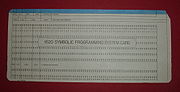
- 1620 Symbolic Programming System (SPS) (assembly languageAssembly languageAn assembly language is a low-level programming language for computers, microprocessors, microcontrollers, and other programmable devices. It implements a symbolic representation of the machine codes and other constants needed to program a given CPU architecture...
) - FORTRANFortranFortran is a general-purpose, procedural, imperative programming language that is especially suited to numeric computation and scientific computing...
- FORTRAN II - required 40,000 digits or more of memory
- GOTRAN - simplified, interpreted version of FORTRAN for "load and go" operation
- Monitor I and Monitor II - disk operating systemOperating systemAn operating system is a set of programs that manage computer hardware resources and provide common services for application software. The operating system is the most important type of system software in a computer system...
s.
The Monitors provided disk based versions of 1620 SPS IId, FORTRAN IId as well as a DUP (Disk Utility Program). Both Monitor systems required 20,000 digits or more of memory and 1 or more 1311 disk drives.
A collection of IBM 1620 related manuals in PDF format exists at
Operating procedures
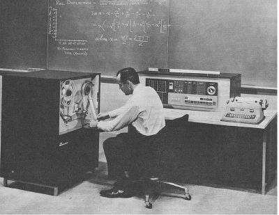
The "operating system" for the computer constituted the operator, who would use controls on the computer console to load programs from the available bulk storage media such as decks of punched cards or rolls of paper tape that were kept in cabinets nearby. Later, the model 1311 disc storage device attached to the computer enabled a reduction in the fetch and carry of card decks or paper tape rolls, and a simple "Monitor" operating system could be loaded to help in selecting what to load from disc.A standard preliminary was to clear the computer memory of any previous user's detritus - being magnetic cores, the memory retained its last state even if the power had been switched off. This was effected by using the console facilities to load a simple computer program via typing its machine code at the console typewriter, running it, and stopping it. This was not challenging as only one instruction was needed such as 160001000000, loaded at address zero and following. This meant transmit field immediate (the 16: two digit op-codes) to address 00010 the immediate constant field having the value 00000 (five digit operand fields, the second being from address 11 back to 7), decrementing source and destination addresses until such time as a digit with a "flag" was copied. This was the normal machine code means of copying a constant of up to five digits. The digit string was addressed at its low-order end and extended through lower addresses until a digit with a flag marked its end. But for this instruction, no flag would ever be found because the source digits had shortly before been overwritten by digits lacking a flag. Thus the operation would roll around memory (even overwriting itself) filling it with all zeroes until the operator grew tired of watching the roiling of the indicator lights and pressed the Instant Stop - Single Cycle Execute button. Each 20,000 digit module of memory took just under one second to clear. On the 1620 II
IBM 1620 Model II
The IBM 1620 Model II was a vastly improved implementation, compared to the original Model I, of the IBM 1620 scientific computer architecture....
this instruction would NOT work (due to certain optimizations in the implementation). Instead there was a button on the console called Modify which when pressed together with the Check Reset button, when the computer was in Manual mode, would set the computer in a mode that would clear all of memory in a tenth of one second regardless of how much memory you had; when you pressed Start. It also stopped automatically when memory was cleared, instead of requiring the operator to stop it.
Other than typing machine code at the console, a program could be loaded via either the paper tape reader, the card reader, or any disk drive. Loading from either tape or disk required first typing a "bootstrap" routine on the console typewriter.
The card reader made things easier because it had a special Load button to signify that the first card was to be read into the computer's memory (starting at address 00000) and executed (as opposed to just starting the card reader, which then awaits commands from the computer to read cards) - this is the "bootstrap" process that gets into the computer just enough code to read in the rest of the code (from the card reader, or disc, or...) that constitutes the loader that will read in and execute the desired program.
Programs were prepared ahead of time, offline, on paper tape or punched cards. But usually the programmers were allowed to run the programs personally, hands-on, instead of submitting them to operators as was the case with mainframe computers at that time. And the console typewriter allowed entering data and getting output in an interactive fashion, instead of just getting the normal printed output from a blind batch run on a pre-packaged data set. As well, there were four program switch
Sense switch
A sense switch or program switch, is a switch on the console of a computer whose state can be tested by conditional branch instructions in software. Most early computers had several sense switches...
es on the console whose state a running program could test and so have its behavior directed by its user. The computer operator could also stop a running program (or it may come to a deliberately programmed stop) then investigate or modify the contents of memory: being decimal-based, this was quite easy; even floating-point numbers could be read at a glance. Execution could then be resumed, from any desired point. Aside from debugging, scientific programming is typically exploratory, by contrast to commercial data processing where the same work is repeated on a regular schedule.
Console
- For details of console lights, switches, and procedures see the respective articles on the IBM 1620 Model IIBM 1620 Model IThe IBM 1620 Model I was the original implementation of the IBM 1620 scientific computer, introduced in 1959.This unit was produced as inexpensively as IBM could make it, in order to keep the price low...
or IBM 1620 Model IIIBM 1620 Model IIThe IBM 1620 Model II was a vastly improved implementation, compared to the original Model I, of the IBM 1620 scientific computer architecture....
.
The most important items on the 1620's console were a pair of buttons labeled Insert & Release, and the electric typewriter.
- Insert – Pressing this key with the computer in Manual mode reset the program counter (in the MARS core memory) to zero, switched the computer into Automatic and Insert modes, and simulated the execution of a Read Numeric from Typewriter to address zero (unlocked the typewriter keyboard, shifted the typewriter into numeric mode). Note: unlike a real Read Numeric from Typewriter, Insert mode would force a Release after 100 digits had been typed to prevent overwriting the arithmetic tables.
- Release – Pressing this key while doing a Read from the Typewriter terminated the Read, switched the computer into Manual mode, and locked the typewriter keyboard.
The typewriter is used for operator input/output, both as the main console control of the computer and for program controlled input/output. Later models of the typewriter had a special key marked R-S that combined the functions of the console Release & Start buttons (this would be considered equivalent to an Enter key on a modern keyboard). Note: several keys on the typewriter did not generate input characters, these included Tab and Return (the 1620's alphameric and numeric BCD character sets lacked character codes for these keys).
The next most important items on the 1620's console were the buttons labeled Start, Stop-SIE, and Instant Stop-SCE.
- Start – Pressing this key with the computer in Manual mode switched the computer to Automatic mode (causing the computer to begin executing at the address in the program counter).
- Stop-SIE – Pressing this key with the computer in Automatic mode switched the computer to Manual mode when the currently executing instruction completes. Pressing this key with the computer in Manual mode switched the computer into Automatic mode for one instruction.
- Instant Stop-SCE – Pressing this key with the computer in Automatic mode switched the computer into Automatic/Manual mode at the end of the current memory cycle. Pressing this key with the computer in Manual or Automatic/Manual mode switched the computer into Automatic/Manual mode and executed one memory cycle.
For program debugging there were the buttons labeled Save & Display MAR.
- Save – Pressing this key with the computer in Manual mode saved the program counter into another register in the MARS core memory and activated Save mode.
When a Branch Back instruction was executed in Save mode, it copied the saved value back to the program counter (instead of copying the return address register as it normally did) and deactivated Save mode.
This was used during debugging to remember where the program had been stopped to allow it to be resumed after the debugging instructions that the operator had typed on the typewriter had finished. Note: the MARS register used to save the program counter in was also used by the Multiply instruction, so this instruction and the Save mode were incompatible! However there was no need to use multiply in debugging code, so this was not considered to be a problem.
- Display MAR – Pressing this key with the computer in Manual mode displayed the selected MARS register and the contents of the memory at that address on the console lamps.
"Breakpoint" procedure Notes Press Stop-SIE Stop the computer at the end of the current instruction. Press Save Save the address to resume execution at. Press Insert Unlocks typewriter keyboard and shifts into numeric mode. Type 35xxxxx0010036xxxxx0010042
xxxxx is the address that you plan to set the breakpoint at. Press Release Locks typewriter keyboard. Press Start Begin execution. Allow the 12 digit instruction to print out. Press Release Stops the Dump Numeric. Press Start Begin execution. Type 48 Replace the opcode of the instruction to "break" at with a Halt opcode. Press Release Locks typewriter keyboard. Press Start Resume execution. Wait until the computer halts at the "breakpoint". Press Insert Unlocks typewriter keyboard and shifts into numeric mode. Type 36xxxxx0010049xxxxx
xxxxx is the address that you previously set the breakpoint at, you are now going to clear it. Press Release Locks typewriter keyboard. Press Start Begin execution. Type oo oo is the 2 digit opcode the original 12 digit instruction previously printed out. Press Release Locks typewriter keyboard. Press Stop-SIE The machine is now ready to resume execution from the location of the (now cleared) "breakpoint". You can perform any required debugging actions now, before continuing.
Paper Tape reader/punch
The 1621 Tape reader and 1624 Tape punch controls.- Power switch – With this switch on the reader is powered anytime the 1620 is powered.
- Reel-Strip switch – This switch selects whether Reels or Strips of paper tape are used.
- Reel power key – Applies power to the supply and takeup Reels to position the tape for reading and places the reader in ready state.
- Non-process runout key – Feeds tape until the reader is empty and takes the reader out of ready state.
Bootstrap procedure Notes Press Insert Unlocks typewriter keyboard and shifts into numeric mode. Type 36xxxxx0030049yyyyy
xxxxx is the address to load the tape into.
yyyyy is the address to begin execution.Press Release Locks typewriter keyboard. Press Start Begin execution.
Card reader/punch
The 1622 Card reader/punch controls were divided into three groups: 3 punch control rocker switches, 6 buttons, and 2 reader control rocker switches.Punch Rocker switches:
- Punch Off/Punch On – This rocker turned the punch mechanism off or on.
- Select No-Stop/Select Stop – This rocker selected if mispunched cards (deposited in the punch error select stacker instead of the normal punch stacker) let the punch continue or caused a check stop.
- Non-Process Runout – This rocker with the punch hopper empty, "ranout" remaining cards from the punch mechanism.
Buttons:
- Start punch – Pressing this key with the punch idle and on, started the punch. The computer could now punch cards.
- Stop punch – Pressing this key with the punch active, stopped the punch.
- Check Reset – Pressing this key reset all "error check" conditions in the reader and punch.
- Load – Pressing this key with the reader idle and on and the computer in Manual mode started the reader, reset the program counter (in the MARS core memory) to zero, read one card into the reader's buffer and checked the card for errors, and simulated the execution of a Read Numeric from Card Reader to address zero (reading the 80 characters of the reader's buffer into memory addresses 00000 to 00079), then switched the computer into Automatic mode (starting execution at the address in the program counter).
- Stop reader – Pressing this key with the reader active, stopped the reader.
- Start reader – Pressing this key with the reader idle and on, started the reader and read one card into the reader's buffer and checked the card for errors. The computer could now read cards.
Reader Rocker switches:
- Non-Process Runout – This rocker with the read hopper empty, "ranout" remaining cards from the reader mechanism.
- Reader Off/Reader On – This rocker turned the reader mechanism off or on.
Bootstrap procedure Notes Press Load
Disk drives
The 1311 Disk drive controls.- Module light – This light shows the drive number. When it lights the drive is ready for access.
- Compare-Disable key-switch – When this (Master only) switch is in the ON position and the Write Address button is pressed a full track write may be performed without comparing addresses. Used to format disk packs.
- Select Lock light – When this (Master only) lights one or more of the drives has malfunctioned. No disk access can be performed.
- Write Address button/light – This (Master only) key controls writing sector addresses. Pressing it toggles this enable and turns its light on/off.
- Enable-Disable toggle-switch – This switch enables or disables access to the drive. If this switch is disabled on the Master, all drives are disabled regardless of the state of their own switches. Also controls the disk usage time meter(s).
- Start Stop button – Pressing this key starts or stops the disk drive motor. The motor must be stopped to open the lid and change disk packs.
Bootstrap procedure Notes Press Insert Unlocks typewriter keyboard and shifts into numeric mode. Type 3400032007013600032007024902402
x
y1963611300102x - Specifies source of Monitor control cards: 1=typewriter, 3=paper tape, 5=cards
y - Specifies disk drive on which Monitor resides: 1, 3, 5, 7
02402 is the address of the entry point of the Monitor program.Press Release Locks typewriter keyboard. Press Start Begin execution.
| Restart procedure | Notes |
|---|---|
| Press Insert | Unlocks typewriter keyboard and shifts into numeric mode. |
| Type 490225FLG6 |
02256 is the address of the location containing the address of the restart point of the Monitor program. Note: this procedure assumes the Monitor is already loaded in memory |
| Press Release | Locks typewriter keyboard. |
| Press Start | Begin execution. |
General
The FORTRAN II compiler and SPS assembler were somewhat cumbersome to use by modern standards, however, with repetition, the procedure soon became automatic and you no longer thought about the details involved.| FORTRAN II compilation procedure | Notes |
|---|---|
Set the Program Switches as follows:
|
Pass I options |
| Set Overflow Check switch to Program and all others to Stop | |
| Press Reset | |
| Load blank cards (face down 12-edge first) into the Punch hopper then press Punch Start | |
| Load Pass I of the compiler (face down 9-edge first) into the Read hopper then press Load | Wait for Pass I to load and print on the typewriter "ENTER SOURCE PROGRAM, PRESS START" |
| Remove Pass I of the compiler from the Read stacker | |
| Load the program source deck (face down 9-edge first) into the Read hopper then press Start | Wait for Pass I to complete and print on the typewriter "TURN SW 1 ON FOR SYMBOL TABLE, PRESS START" |
| Turn Program Switch 1 OFF then press Start | If a symbol table listing is desired for debugging, turn Program Switch 1 ON instead. The symbol table listing will be printed on the typewriter. Wait for Pass I to print on the typewriter "END OF PASS 1" |
| Set the Program Switches as follows:
|
Pass II options |
| Set Overflow Check switch to Program and all others to Stop | |
| Press Reset | |
| Load blank cards (face down 12-edge first) into the Punch hopper then press Punch Start | |
| Load Pass II of the compiler (face down 9-edge first) into the Read hopper then press Load | Wait for Pass II to load |
| Remove Pass II of the compiler from the Read stacker | |
| Remove the intermediate output of Pass I from the Punch stacker, then load it (face down 9-edge first) into the Read hopper and press Reader Start then Start | Wait for Pass II to complete and print on the typewriter "SW 1 ON TO PUNCH SUBROUTINES, PRESS START" |
| Remove the intermediate output from the Reader stacker | |
| Turn Program Switch 1 ON, load the Subroutine deck (face down 9-edge first) into the Read hopper, then press Reader Start then Start | Wait for Pass II to print on the typewriter "END OF PASS II" |
| Remove the Subroutine deck from the Reader stacker and the completed Object deck from the Punch stacker |
GOTRAN was much simpler to use, as it directly produced an executable in memory. However it was not a complete FORTRAN implementation.
To improve this various third-party FORTRAN compilers were developed. One of these was developed by Bob Richardson, a programmer at Rice University
Rice University
William Marsh Rice University, commonly referred to as Rice University or Rice, is a private research university located on a heavily wooded campus in Houston, Texas, United States...
, the FLAG (FORTRAN Load-and-Go) compiler. Once the FLAG deck had been loaded, all that was needed was to load the source deck to get directly to the output deck; FLAG stayed in memory, so it was immediately ready to accept the next source deck. This was particularly convenient for dealing with many small jobs. For instance, at Auckland University a batch job processor for student assignments (typically, many small programs not requiring much memory) chugged through a class lot rather faster than the later IBM 1130
IBM 1130
The IBM 1130 Computing System was introduced in 1965. It was IBM's least-expensive computer to date, and was aimed at price-sensitive, computing-intensive technical markets like education and engineering. It succeeded the IBM 1620 in that market segment. The IBM 1800 was a process control variant...
did with its disk-based system. The compiler remained in memory, and the student's program had its chance in the remaining memory to succeed or fail, though a bad failure might disrupt the resident compiler.
Later, disk storage devices were introduced, removing the need for working storage on card decks. The various decks of cards constituting the compiler and loader no longer need be fetched from their cabinets but could be stored on disk and loaded under the control of a simple disk-based operating system: a lot of activity becomes less visible, but still goes on.
Since the punch side of the card reader-punch didn't edge-print the characters across the top of the cards, one had to take any output decks over to a separate machine
Unit record equipment
Before the advent of electronic computers, data processing was performed using electromechanical devices called unit record equipment, electric accounting machines or tabulating machines. Unit record machines were as ubiquitous in industry and government in the first half of the twentieth century...
, typically an IBM 557
IBM 557
The IBM 557 Alphabetic Interpreter allowed holes in punched cards to be interpreted and the Hollerith punched card characters printed on any row or column, selected by a plugboard control panel. The machine was a synchronous system where brushes would glide over a hole in a punched card and...
Alphabetic Interpreter, that read each card and printed its contents along the top. Listings were usually generated by punching a listing deck and using an IBM 407
IBM 407
The IBM 407 Accounting Machine, introduced in 1949, was one of a long line of IBM tabulating machines dating back to the days of Herman Hollerith. It was the central component of any unit record equipment shop. In the late 1950s, the 407 was adapted as an input/output device on early computers,...
accounting machine to print the deck.
Hardware implementation
Most of the logic circuitry of the 1620 was a type of resistor-transistor logicResistor-transistor logic
Resistor–transistor logic is a class of digital circuits built using resistors as the input network and bipolar junction transistors as switching devices...
(RTL) using "drift" transistor
Drift-field transistor
The drift-field transistor, also called the drift transistor or graded base transistor, is a type of high-speed bipolar junction transistor having a doping-engineered electric field in the base to reduce the charge carrier base transit time....
s (a type of transistor invented by Herbert Kroemer
Herbert Kroemer
Herbert Kroemer , a professor of electrical and computer engineering at the University of California, Santa Barbara, received his Ph.D. in theoretical physics in 1952 from the University of Göttingen, Germany, with a dissertation on hot electron effects in the then-new transistor, setting the stage...
in 1953) for their speed, that IBM referred to as SDTRL. Other IBM circuit types used were referred to as: Alloy (some logic, but mostly various non-logic functions, named for the kind of transistors used), CTRL (another type of RTL, but slower than SDTRL), CTDL (a type of diode-transistor logic
Diode-transistor logic
Diode–transistor logic is a class of digital circuits that is the direct ancestor of transistor–transistor logic. It is called so because the logic gating function is performed by a diode network and the amplifying function is performed by a transistor .- Implementations :The DTL circuit shown in...
(DTL)), and DL (another type of RTL, named for the kind of transistor used, "drift" transistors). Typical logic levels of all these circuits (S Level) were high: 0 V to -0.5 V, low: -6 V to -12 V. Transmission line
Transmission line
In communications and electronic engineering, a transmission line is a specialized cable designed to carry alternating current of radio frequency, that is, currents with a frequency high enough that its wave nature must be taken into account...
logic levels of SDTRL circuits (C Level) were high: 1 V, low: -1 V. Relay circuits used either of two logic levels (T Level) high: 51 V to 46 V, low: 16 V to 0 V or (W Level) high: 24 V, low: 0 V.
These circuits were constructed of individual discrete components mounted on single sided paper-epoxy printed circuit
Printed circuit
Printed circuit may refer to:* Printed circuit board* Printed Circuit Corporation, an electronics manufacturer...
boards 2.5 by with a 16-pin gold
Gold
Gold is a chemical element with the symbol Au and an atomic number of 79. Gold is a dense, soft, shiny, malleable and ductile metal. Pure gold has a bright yellow color and luster traditionally considered attractive, which it maintains without oxidizing in air or water. Chemically, gold is a...
plated edge connector
Edge connector
An edge connector is the portion of a printed circuit board consisting of traces leading to the edge of the board that are intended to plug into a matching socket. The edge connector is a money-saving device because it only requires a single discrete female connector , and they also tend to be...
, that IBM referred to as SMS cards (Standard Modular System
Standard Modular System
The Standard Modular System was a system of standard transistorized circuit boards and mounting racks developed by IBM in the late 1950s, originally for the IBM 7030 Stretch. They were used throughout IBM's second generation computers, peripherals, the 7000 series, the 1400 series, and the 1620...
). The amount of logic on one card was similar to that in one 7400 series
7400 series
The 7400 series of transistor-transistor logic integrated circuits are historically important as the first widespread family of TTL integrated circuit logic. It was used to build the mini and mainframe computers of the 1960s and 1970s...
SSI or simpler MSI package (e.g., 3 to 5 logic gates or a couple of flip-flops).
These boards were inserted into sockets mounted in door-like racks which IBM referred to as gates. The machine had the following "gates" in its basic configuration:
- "Gate A" - Forward hinged gate that swings out the back for access, after "Gate B".
- "Gate B" - Rear hinged gate that swings out the back for access.
- "Gate C" - Slides out back for access. Console Typewriter interface. Mostly relayRelayA relay is an electrically operated switch. Many relays use an electromagnet to operate a switching mechanism mechanically, but other operating principles are also used. Relays are used where it is necessary to control a circuit by a low-power signal , or where several circuits must be controlled...
logic. - "Gate D" - Slides out back for access. Standard I/O interface.
There were two different types of core memory used in the 1620:
- Main memory
- Coincident Current X-Y Line addressing
- 20,000, 40,000, or 60,000 Digits
- 12-bit, even-odd Digit Pair
- 12 one bit planes in each module, 1 to 3 modules
- 10,000 cores per plane
- Coincident Current X-Y Line addressing
- Memory Address Register Storage (MARS) memory
- Word Line addressing
- 16 Words, minimum of 8 used in basic configuration
- Single Word read, multiple Word clear/write
- 24-bit, 5 Digit decimal Memory Address (no 8 - Ten Thousand bit stored)
- 1 plane
- 384 cores
- Word Line addressing
The address decoding logic of the Main memory also used two planes of 100 pulse transformer cores per module to generate the X-Y Line half-current pulses.
There were two models of the 1620, each having totally different hardware implementations:
- IBM 1620 IIBM 1620 Model IThe IBM 1620 Model I was the original implementation of the IBM 1620 scientific computer, introduced in 1959.This unit was produced as inexpensively as IBM could make it, in order to keep the price low...
- IBM 1620 IIIBM 1620 Model IIThe IBM 1620 Model II was a vastly improved implementation, compared to the original Model I, of the IBM 1620 scientific computer architecture....
A computer for the "small scientific market"
In 1958 IBM assembled a team at the Poughkeepsie, New YorkPoughkeepsie (city), New York
Poughkeepsie is a city in the state of New York, United States, which serves as the county seat of Dutchess County. Poughkeepsie is located in the Hudson River Valley midway between New York City and Albany...
development laboratory to study the "small scientific market". Initially the team consisted of Wayne Winger (Manager), Robert C. Jackson, and William H. Rhodes.
Requirements and design
The competing computers in this market were the Librascope LGP-30 and the Bendix G-15Bendix G-15
The Bendix G-15 computer was introduced in 1956 by the Bendix Corporation, Computer Division, Los Angeles, California. It was about 5 by 3 by 3 ft and weighed about 950 lb . The base system, without peripherals, cost $49,500. A working model cost around $60,000. It could also be rented for...
; both were drum memory
Drum memory
Drum memory is a magnetic data storage device and was an early form of computer memory widely used in the 1950s and into the 1960s, invented by Gustav Tauschek in 1932 in Austria....
machines. IBM's smallest computer at the time was the popular IBM 650
IBM 650
The IBM 650 was one of IBM’s early computers, and the world’s first mass-produced computer. It was announced in 1953, and over 2000 systems were produced between the first shipment in 1954 and its final manufacture in 1962...
, a fixed word length decimal machine that also used drum memory. All three used vacuum tube
Vacuum tube
In electronics, a vacuum tube, electron tube , or thermionic valve , reduced to simply "tube" or "valve" in everyday parlance, is a device that relies on the flow of electric current through a vacuum...
s. It was concluded that IBM could offer nothing really new in that area. To compete effectively would require use of technologies that IBM had developed for larger computers, yet the machine would have to be produced at the least possible cost.
To meet this objective, the team set the following requirements:
- Core memory
- Restricted instruction set
- No divide or floating point instructions, use subroutines in the "general program package"
- Wherever possible replace hardware with existing logical machine functions
- No arithmetic circuits, use tables in core memory
- Least expensive Input/Output possible
- No punch cards, use paper tape
- No printer, use operator's console typewriter
The internal code name CADET was selected for the machine. One of the developers says that this stood for "Computer with ADvanced Economic Technology", however others recall it as simply being one half of "SPACE - CADET", where SPACE was the internal code name of the IBM 1401
IBM 1401
The IBM 1401 was a variable wordlength decimal computer that was announced by IBM on October 5, 1959. The first member of the highly successful IBM 1400 series, it was aimed at replacing electromechanical unit record equipment for processing data stored on punched cards...
machine, also then under development.
The prototype
The team expanded with the addition of Anne Deckman, Kelly B. Day, William Florac, and James Brenza. They completed the CADET prototype in the spring of 1959.Meanwhile the San Jose, California
San Jose, California
San Jose is the third-largest city in California, the tenth-largest in the U.S., and the county seat of Santa Clara County which is located at the southern end of San Francisco Bay...
facility was working on a proposal of its own. IBM could only build one of the two and the Poughkeepsie
Poughkeepsie (city), New York
Poughkeepsie is a city in the state of New York, United States, which serves as the county seat of Dutchess County. Poughkeepsie is located in the Hudson River Valley midway between New York City and Albany...
proposal won because "the San Jose version is top of the line and not expandable, while your proposal has all kinds of expansion capability - never offer a machine that cannot be expanded".
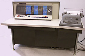
 |
| IBM 1620 Model I Level A (prototype), as it appeared in the IBM announcement of the machine. |
Management was not entirely convinced that core memory could be made to work in small machines, so Gerry Ottaway was loaned to the team to design a drum memory
Drum memory
Drum memory is a magnetic data storage device and was an early form of computer memory widely used in the 1950s and into the 1960s, invented by Gustav Tauschek in 1932 in Austria....
as a backup. During acceptance test
Acceptance test
In engineering and its various subdisciplines, acceptance testing is a test conducted to determine if the requirements of a specification or contract are met...
ing by the Product Test Lab, repeated core memory failures were encountered and it looked likely that management's predictions would come true. However, at the last minute it was found that the muffin fan used to blow hot air through the core stack was malfunctioning, causing the core to pick up noise pulses and fail to read correctly. After the fan problem was fixed, there were no further problems with the core memory and the drum memory design effort was discontinued as unnecessary.
Transferred to San Jose for production
Following announcement of the IBM 1620 on October 21, 1959, due to an internal reorganization of IBM, it was decided to transfer the computer from the Data Processing Division at Poughkeepsie (large scale mainframe computers only) to the General Products Division at San Jose (small computers and support products only) for manufacturing.Following transfer to San Jose, someone there jokingly suggested that the code name CADET actually stood for "Can't Add, Doesn't Even Try", referring to the use of addition tables in memory rather than dedicated addition circuitry. This stuck and became very well known among the user community.
Implementation "levels"
- Model IIBM 1620 Model IThe IBM 1620 Model I was the original implementation of the IBM 1620 scientific computer, introduced in 1959.This unit was produced as inexpensively as IBM could make it, in order to keep the price low...
- Level A; prototype.
- All flip-flopFlip-flop (electronics)In electronics, a flip-flop or latch is a circuit that has two stable states and can be used to store state information. The circuit can be made to change state by signals applied to one or more control inputs and will have one or two outputs. It is the basic storage element in sequential logic...
s in the design were transistorTransistorA transistor is a semiconductor device used to amplify and switch electronic signals and power. It is composed of a semiconductor material with at least three terminals for connection to an external circuit. A voltage or current applied to one pair of the transistor's terminals changes the current...
ized versions of the original Eccles-Jordan trigger circuit. While this machine was fully functional, it was found that the capacitorCapacitorA capacitor is a passive two-terminal electrical component used to store energy in an electric field. The forms of practical capacitors vary widely, but all contain at least two electrical conductors separated by a dielectric ; for example, one common construction consists of metal foils separated...
coupling used in these proved troublesome in the noisy signal environment of relayRelayA relay is an electrically operated switch. Many relays use an electromagnet to operate a switching mechanism mechanically, but other operating principles are also used. Relays are used where it is necessary to control a circuit by a low-power signal , or where several circuits must be controlled...
s and timing camCamA cam is a rotating or sliding piece in a mechanical linkage used especially in transforming rotary motion into linear motion or vice-versa. It is often a part of a rotating wheel or shaft that strikes a lever at one or more points on its circular path...
driven switchSwitchIn electronics, a switch is an electrical component that can break an electrical circuit, interrupting the current or diverting it from one conductor to another....
es used to drive the console typewriter. This necessitated a complete redesign of the machine to use S-R flip-flops instead (except for two triggers used to generate clocks for the S-R flip-flops). However usage of the term Trigger was retained in all the documentation when referring to a flip-flop, as it was IBM's conventional term (as alphamerics was their term for alphanumerics). - This is the only level using a one piece vertical control panel, when the design was transferred from Poughkeepsie to San Jose it was redesigned to the two piece angled control panel used on all production models.
- All flip-flop
- Level B; first production.
- This is the only level using a burnished aluminum lower control panel, later levels finished this panel with white.
- Level C; introduction of 1622 card reader/punch.
- Level D; introduction of 1311 disk drives and addition of optional "Gate J" containing disk control logic.
- Level E; introduction of Floating Point option.
- Level F
- Level G; introduction of Interrupt option (needed for IBM 1710IBM 1710The IBM 1710 was a process control system that IBM introduced in March 1961. It used either a 1620 I or a 1620 II Computer and specialized I/O devices .The IBM 1620 used in the 1710 system was modified in several ways, the most obvious was the addition of a very...
).- Did not support BT & BB subroutines in interrupt code!
- Disk control logic on "Gate J" logic merged into "Gate A" & "Gate B".
- Made possible because much of logic was compacted using cards designed for the Model II.
- Level H; improved Interrupt option that supported BT & BB subroutines in interrupt code.
- Final version of the Model I.
- Level A; prototype.
- Model IIIBM 1620 Model IIThe IBM 1620 Model II was a vastly improved implementation, compared to the original Model I, of the IBM 1620 scientific computer architecture....
(no information on "Levels" available at this time)
-
- The 1620 Model II introduced basic ALU hardware for addition and subtraction (making "Can't Add, Doesn't Even Try" no longer applicable) and index registerIndex registerAn index registerCommonly known as a B-line in early British computers. in a computer's CPU is a processor register used for modifying operand addresses during the run of a program, typically for doing vector/array operations...
s.- Model III
- Work was begun on a 1620 Model III but the project was quickly canceled as IBM wanted to promote sales of their new System/360System/360The IBM System/360 was a mainframe computer system family first announced by IBM on April 7, 1964, and sold between 1964 and 1978. It was the first family of computers designed to cover the complete range of applications, from small to large, both commercial and scientific...
and discontinue the old lines.
- Work was begun on a 1620 Model III but the project was quickly canceled as IBM wanted to promote sales of their new System/360
- Model III
- The 1620 Model II introduced basic ALU hardware for addition and subtraction (making "Can't Add, Doesn't Even Try" no longer applicable) and index register
Patents
- Multiplying Computer
- Compact Data Lookup Table
|
- Computer with Table Lookup Arithmetic Unit Feature
- Dividing Computer
|
Related peripheral units

- IBM 1621 - Paper tape reader
- IBM 1622 - Punch card reader/punch
- IBM 1624 - Paper tape punch (sat inside the 1621 on a shelf)
- IBM 1626 - Plotter controller
- IBM 1627IBM 1627The IBM 1627 was a rebranded Calcomp plotter sold by IBM for use with the IBM 1620, and, later, the IBM 1130 computers. It became perhaps the first non-IBM peripheral that IBM allowed to be attached to one of its computers....
- Plotter - IBM 1311 - Disk drive: Model 3 master drive controlling up to 3–Model 2 slave drives.
- IBM 1443 - Printer, flying type bar
- IBM 1405 - Disk Drive available as RPQ (request price quotation)
Notable Uses
An IBM 1620 model II was used by Vearl N. Huff, NASA Headquarters (FOB 10B, Washington DC) to program a three dimensional simulation in Fortran of the tethered Gemini capsule - Agena rocket module two-body problem at a time when it was not completely understood if it was safe to tether two objects together in space due to possible elastic tether induced collisions. The same computer was also used to simulate the orbits of the Gemini flights, producing printer-art charts of each orbit. These simulation were run over-night and the data examined the next day.Use in film and television
The fictional computer Colossus of Colossus: The Forbin ProjectColossus: The Forbin Project
Colossus: The Forbin Project is an American science fiction thriller film. It is based upon the 1966 novel Colossus, by Dennis Feltham Jones, about a massive American defense computer, named Colossus, becoming sentient and deciding to assume control of the world.-Plot:Dr. Charles A...
used about a dozen scrapped 1620 front panels purchased on the surplus market, in various orientations. A similar arrangement was used in a late episode of The Man from U.N.C.L.E.
The Man from U.N.C.L.E.
The Man from U.N.C.L.E. is an American television series that was broadcast on NBC from September 22, 1964, to January 15, 1968. It follows the exploits of two secret agents, played by Robert Vaughn and David McCallum, who work for a fictitious secret international espionage and law-enforcement...
to portray a THRUSH supercomputer.
External links
- IBM 1620 restoration project
- 1620 Data Processing System
- IBM 1620 documents from bitsavers.org
- IBM 1620 Simulator Applet (part of the IBM 1620 restoration project)