
Air flow bench
Encyclopedia
Engine
An engine or motor is a machine designed to convert energy into useful mechanical motion. Heat engines, including internal combustion engines and external combustion engines burn a fuel to create heat which is then used to create motion...
component and is related to the more familiar wind tunnel
Wind tunnel
A wind tunnel is a research tool used in aerodynamic research to study the effects of air moving past solid objects.-Theory of operation:Wind tunnels were first proposed as a means of studying vehicles in free flight...
.
Used primarily for testing the intake and exhaust ports of cylinder head
Cylinder head
In an internal combustion engine, the cylinder head sits above the cylinders on top of the cylinder block. It closes in the top of the cylinder, forming the combustion chamber. This joint is sealed by a head gasket...
s of internal combustion engine
Internal combustion engine
The internal combustion engine is an engine in which the combustion of a fuel occurs with an oxidizer in a combustion chamber. In an internal combustion engine, the expansion of the high-temperature and high -pressure gases produced by combustion apply direct force to some component of the engine...
s. It is also used to test the flow capabilities of any component such as air filters, carburetors, manifolds or any other part that is required to flow gas. It is one of the primary tools of high performance engine builders and porting
Cylinder head porting
Cylinder head porting refers to the process of modifying the intake and exhaust ports of an internal combustion engine to improve the quality and quantity of the air flow. Cylinder heads, as manufactured, are usually suboptimal due to design and manufacturing constraints...
cylinder heads would be strictly hit or miss without it.
A flow bench consists of an air pump of some sort, a metering element
Flow measurement
Flow measurement is the quantification of bulk fluid movement. Flow can be measured in a variety of ways.Positive-displacement flow meters acumulate a fixed volume of fluid and then count the number of times the volume is filled to measure flow...
, pressure and temperature measuring instruments such as manometers, and various controls. The test piece is attached in series with the pump and measuring element and air is pumped through the whole system. Therefore all the air passing through the metering element also passes through the test piece. Because the flow through the metering element is known and the flow through the test piece is the same, it is also known.
Air pump
The air pumpAir pump
An air pump is a device for pushing air. Examples include a bicycle pump, pumps that are used to aerate an aquarium or a pond via an airstone; a gas compressor used to power a pneumatic tool, air horn or pipe organ; a bellows used to encourage a fire; and a vacuum pump.The first effective air pump...
used must be able to deliver the volume required at the pressure required. Most flow testing is done at 10 and 28 inches of water pressure (2.5 to 7 kilopascals). Although other test pressures will work, the results would have to be converted for comparison to the work of others. The pressure developed must account for the test pressure plus the loss across the metering element plus all other system losses. The greater the accuracy of the metering element the greater is the loss. Flow volume of between 100 and 600 cubic feet per minute (0.05 to 0.28 m³/s) would serve almost all applications depending on the size of the engine under test.
Any type of pump that can deliver the required pressure difference and flow volume can be used. Most often used is the centrifugal dynamic type, which is familiar to most as a vacuum cleaner. Multistaged axial-flow fan types and positive displacement types (piston and rotary) could also be used with suitable provisions for damping the pulsations. The pressure ratio of a single fan blade is too low and cannot be used.
Metering element
There are several possible types of metering element in use. Flow benches ordinarily use three types: orifice plateOrifice plate
An orifice plate is a device used for measuring the volumetric flow rate. It uses the same principle as a Venturi nozzle, namely Bernoulli's principle which states that there is a relationship between the pressure of the fluid and the velocity of the fluid...
, venturi meter
Venturi effect
The Venturi effect is the reduction in fluid pressure that results when a fluid flows through a constricted section of pipe. The Venturi effect is named after Giovanni Battista Venturi , an Italian physicist.-Background:...
and pitot/static
Pitot tube
A pitot tube is a pressure measurement instrument used to measure fluid flow velocity. The pitot tube was invented by the French engineer Henri Pitot Ulo in the early 18th century and was modified to its modern form in the mid-19th century by French scientist Henry Darcy...
tube, all of which deliver similar accuracy. Most commercial machines use orifice plates due to their simple construction and the ease of providing multiple flow ranges. Although the venturi offers substantial improvements in efficiency, its cost is higher.
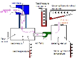
Instrumentation
Air flow conditions must be measured at two locations, across the test piece and across the metering element. The pressure difference across the test piece allows the standardization of tests from one to another. The pressure across the metering element allows calculation of the actual flow through the whole system.The pressure across the test piece is typically measured with a U tube
Oscillating U-tube
The oscillating U-tube is a technique to determine the density of liquids and gases based on an electronic measurement of the frequency of oscillation, from which the density value is calculated. This measuring principle is based on the Mass-Spring Model....
manometer while, for increased sensitivity and accuracy, the pressure difference across the metering element is measured with an inclined manometer. One end of each manometer is connected to its respective plenum chamber while the other is open to the atmosphere.
Ordinarily all flow bench manometers measure in inches of water although the inclined manometer's scale is usually replaced with a logarithmic scale
Logarithmic scale
A logarithmic scale is a scale of measurement using the logarithm of a physical quantity instead of the quantity itself.A simple example is a chart whose vertical axis increments are labeled 1, 10, 100, 1000, instead of 1, 2, 3, 4...
reading in percentage of total flow of the selected metering element which makes flow calculation simpler.
Temperature must also be accounted for because the air pump will heat the air passing through it making the air down stream of it less dense and more viscous. This difference must be corrected for. Temperature is measured at the test piece plenum and at the metering element plenum. Correction factors are then applied during flow calculations. Some flow bench designs place the air pump after the metering element so that heating by the air pump is not as large a concern.
Additional manometers can be installed for use with hand held probes, which are used to explore local flow conditions in the port.
Flow bench data
The air flow bench can give a wealth of data about the characteristics of a cylinder head or whatever part is tested. The result of main interest is bulk flow. It is the volume of air that flows through the port in a given time. Expressed in cubic feet per minute or cubic meters per second/minute.Valve lift can be expressed as an actual dimension in decimal inches or mm. It can also be specified as a ratio between a characteristic diameter and the lift L/D. Most often used is the valve head diameter. Normally engines have an L/D ratio from 0 up to a maximum of .35. For example, a 1 inches (25.4 mm) valve would be lifted a maximum of 0.350 inch. During flow testing the valve would be set at L/D .05 .1 .15 .2 .25 .3 and readings taken successively. This allows the comparison of efficiencies of ports with other valve sizes, as the valve lift is proportional rather than absolute. For comparison with tests by others the characteristic diameter used to determine lift must be the same.
Flow coefficients are determined by comparing the actual flow of a test piece to the theoretical flow of a perfect orifice
Orifice
An orifice is any opening, mouth, hole or vent, as of a pipe, plate, or a body.* Body orifice* Orifice plate* Calibrated orifice* Nozzle* Back Orifice-See also:* Choked flow* Needle valve* Venturi effect* Flow measurement...
of equal area. Thus the flow coefficient should be a close measure of efficiency. It cannot be exact because the L/D does not indicate the actual minimum size of the duct.
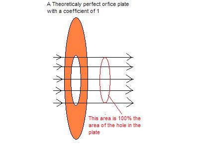
Valve/port coefficient is non dimensional and is derived by multiplying a characteristic physical area of the port and by the bulk flow figures and comparing the result to an ideal orifice of the same area. It is here that air flow bench norms differ from fluid dynamics or aerodynamics at large. The coefficient may be based on the inner valve seat diameter, the outer valve head diameter, the port throat area or the valve open curtain area. Each of these methods are valid for some purpose but none of them represents the true minimum area for the valve/port in question and each results in a different flow coefficient. The great difficulty of measuring the actual minimum area at all the various valve lifts precludes using this as a characteristic measurement. This is due to the minimum area changing shape and location throughout the lift cycle. Because of this non standardization, port flow coefficients are not "true" flow coefficients, which would be based on the actual minimum area in the flow path. Which method to choose depends on what use is intended for the data. Engine simulation applications each require their own specification. If the result is to be compared to the work of others then the same method would have to be selected.
Of less interest is mass flow per minute or second since the test is not of a running engine which would be affected by it. It is the weight of air that flows through the port in a given time. Expressed in pounds per minute/hour or kilograms per second/minute. Mass flow is derived from the volume flow result to which a density correction is applied.
With the information gathered on the flow bench, engine power curve and system dynamics can be roughly estimated by applying various formulae. With the advent of accurate engine simulation software, however, it is much more useful to use flow data to create an engine model for a simulator.
Determining air velocity is a useful part of flow testing. It is calculated as follows:
For one set of English units
Where:
- V = Velocity in feet per minute
- H = Pressure drop across test piece in inches of water measured by the test pressure manometer
- d = density of air in pounds per cubic foot (0.075 pound per cubic foot at standard conditions)
For SI
Si
Si, si, or SI may refer to :- Measurement, mathematics and science :* International System of Units , the modern international standard version of the metric system...
units

Where:
- V = Velocity in meters per second
- H = Pressure drop across test piece in pascals measured by the test pressure manometer
- d = density of air in kilograms per cubic meter (1.20 kilograms per cubic meter at standard conditions)
This represents the highest speed of the air in the flow path, at or near the section of minimum area (through the valve seat at low values of L/D for instance).
Once velocity has been calculated, the volume can be calculated by multiplying the velocity by the orifice area times its flow coefficient.
Limitations
A flow bench is capable of giving flow data which is closely but not perfectly related to actual engine performance. There are a number of limiting factors which contribute to the discrepancy.Steady state flow vs dynamic flow
A flow bench tests ports under a steady pressure difference while in the actual engine the pressure difference varies widely during the whole cycle. The exact flow conditions existing in the flow bench test exist only fleetingly if at all in an actual running engine. Running engines cause the air to flow in strong waves rather than the steady stream of the flow bench. This acceleration/deceleration of the fuel/air column causes effects not accounted for in flow bench tests.
(Note, on the graph, that, in this case, when the intake valve opens, the cylinder pressure is above atmospheric (nearly 50% above or 1.5 bar or 150 kPa). This will cause reverse flow into the intake port until pressure in the cylinder falls below the ports pressure).
Pressure differential
The coefficient of the port may change somewhat at different pressure differentials due to changes in Reynolds number regime leading to a possible loss of dynamic similitude.Flow bench test pressure are typically conducted at 10 to 28 inches of water (2.5 to 7 kPa) while a real engine may see 190 inches of water (47 kPa) pressure difference.
Air only vs mixed gas/fuel mist flow
The flow bench tests using only air while a real engine usually uses air mixed with fuel droplets and fuel vapor, which is significantly different. Evaporating fuel passing through the port-runner has the effect of adding gas to and lowering the temperature of the air stream along the runner and giving the outlet flow rate slightly higher than the flow rate entering the port-runner. A port which flows dry air well might cause fuel droplets to fall out of suspension causing a loss of power not indicated by flow figures alone.Bulk flow vs flow velocity
Large ports and valves can show high flow rates on a flow bench but the velocity can be lowered to the point that the gas dynamics of a real engine are ruined. Overly large ports also contribute to fuel fall out.Even room temperature vs. uneven high temperature
A running engine is much hotter than room temperature and the temperature in various parts of the system vary widely. This affects the actual flow, fuel effects as well as the dynamic wave effects in the engine which do not exist on the flow bench.Physical and mechanical differences
The proximity, shape and movement of the piston as well as the movement of the valve itself significantly alters the flow conditions in a real engine that do not exist in flow bench tests.Exhaust port conditions
The flow simulated on a flow bench bears almost no similarity to the flow in a real exhaust port. Here even the coefficients measured on flow benches are inaccurate. This is due to the very high and wide ranging pressures and temperatures. From the graph above it can be seen that the pressure in the port reaches 2.5 barBar (unit)
The bar is a unit of pressure equal to 100 kilopascals, and roughly equal to the atmospheric pressure on Earth at sea level. Other units derived from the bar are the megabar , kilobar , decibar , centibar , and millibar...
(250 kPa
KPA
KPA may refer to:* Kenya Ports Authority* Kiln phosphoric acid, a dry process to produce phosphoric acid at high temperature in a kiln* Kilopascal , a unit of pressure* Known-plaintext attack, a method of cryptanalysis* Korean People's Army...
) and the cylinder pressure at opening is 6 bar (600 kPa) and more. This is many times more than the capabilities of a typical flow bench of 0.06 bar (6 kPa).
The flow in a real exhaust port can easily be sonic with choked flow occurring and even supersonic flow in areas. The very high temperature causes the viscosity of the gas to increase, all of which alters the Reynolds number drastically.
Added to the above is the profound effect that downstream elements have on the flow of the exhaust port. Far more than upstream elements found on the intake side.
Exhaust port size and flow information might be considered as vague, but there are certain guidelines which are used when creating a base-line to optimum performance. This base line, of course, is further tuned and qualified through a dynometer.
In a given 2-Valve push-rod engine, it's common to see exhaust port sizes roughly 60% the size of the intake. 2-Valve push-rod engines, regardless of how well tuned, don't flow well nor are capable of 100% volumetric efficiency with out extreme amounts of work done, which would make them unsuitable for daily driven applications. Due to the poor flowing characteristics, these styles of engines typically make more torque than horsepower. In that regard, it's often held that complimenting the engine's strengths will offer the best gains. Thusly, exhaust ports and valves are sized much smaller as to facilitate the production of torque.
In a given 4-valve Dual Over Head Cam (DOHC), the head is capable of both far greater flow and velocity characteristics, and is thusly tuned for this. The standard practice for a naturally aspirated 4-valve DOHC engine is to match both the exhaust valves and flow to roughly 85% of the intake size, which compliments horsepower rather than torque. Because DOHC engines flow better than conventional 2-valve engines, the entire combustion process operates at a lower temperature and a higher quality of oxygen concentration is realized with in the cylinder. These two factors contribute largely to the volumetric efficiency of this head design, which typically boasts better fuel economy and performance than 2-valve pushrod engines.
Lastly, in forced-induction applications, an exhaust valve and flow can be as-large-as the intake side – or larger. The notion is that an engine running 1 bar of boost is taking in twice as much as it could on its own, thus there will be roughly twice the exhaust to expunge. To encourage the best flow of exhaust, and quality of oxygen concentration in the cylinder, it's common for turbo/supercharged camshaft
Camshaft
A camshaft is a shaft to which a cam is fastened or of which a cam forms an integral part.-History:An early cam was built into Hellenistic water-driven automata from the 3rd century BC. The camshaft was later described in Iraq by Al-Jazari in 1206. He employed it as part of his automata,...
profiles to have a little overlap so that both the intake and exhaust valves are open at the same time so that the intake air assists in expunging the cylinder.