
Viewing cone
Encyclopedia
Viewing direction
Display device
A display device is an output device for presentation of information in visual or tactile form...
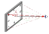
with non-vanishing size is seen by an observer, every point of the display
Display device
A display device is an output device for presentation of information in visual or tactile form...
area is seen from a different direction as illustrated in fig. 1. No two spots on the display
Display device
A display device is an output device for presentation of information in visual or tactile form...
are seen from the same direction. The larger the display
Display device
A display device is an output device for presentation of information in visual or tactile form...
is and the closer the observer is to the display
Display device
A display device is an output device for presentation of information in visual or tactile form...
the more the viewing direction varies over the surface area of the display
Display device
A display device is an output device for presentation of information in visual or tactile form...
.
Colloquially, the viewing direction is often called "viewing angle
Viewing angle
In display technology parlance, viewing angle is the maximum angle at which a display can be viewed with acceptable visual performance. In a technical context, this angular range is called viewing cone defined by a multitude of viewing directions....
". This is an ill-chosen expression which should be avoided, because the viewing direction is specified by two polar angles: the angle of inclination
Inclination
Inclination in general is the angle between a reference plane and another plane or axis of direction.-Orbits:The inclination is one of the six orbital parameters describing the shape and orientation of a celestial orbit...
, θ (measured from the surface normal of the display) and the azimuth angle, Φ, measured in the plane of the display as shown in figure 3.
In fig. 2, the eyeball represents the observer that is looking at a specific spot on the display which is identical to the origin of the polar coordinate system. The green arrow is the viewing direction (i.e. direction of observation). The viewing direction is specified by the angle of inclination
Inclination
Inclination in general is the angle between a reference plane and another plane or axis of direction.-Orbits:The inclination is one of the six orbital parameters describing the shape and orientation of a celestial orbit...
, θ, measured from the surface normal of the display (blue vertical arrow) while the azimuth angle, Φ, is the angle that the projection of the viewing direction onto the surface of the display makes with the x-axis (red arrow). The projection of the viewing direction is shown here as the shadow of the green arrow. The azimuth angle Φ increases counterclockwise as illustrated in figure 3.
Viewing cone
The multitude of directions, from which a display can be seen without artifacts and distortions that would render its intended use impossible (e.g. computerized office work, television, entertainment) is called the viewing cone (even though its shape might be that of a generalized cone).The concept of the viewing cone has been introduced for the first time in the international standard ISO 13406-2
ISO 13406-2
ISO 13406-2 is an ISO standard, with the full title "Ergonomic requirements for work with visual displays based on flat panels -- Part 2: Ergonomic requirements for flat panel displays". It is best known to end consumers for defining a series of flat-panel display "classes" with different numbers...
:2001 "Ergonomic requirements for work with visual displays based on flat panels -- Part 2: Ergonomic requirements for flat panel displays". This standard provides a classification for computer monitors with LCDs according to the range of viewing directions that can safely be used for the intended task (here: office work) without "reduced visual performance". The classification is according to "Viewing Direction Range Classes" with the "range of viewing directions" being equivalent to the viewing cone.
ISO 13406-2
ISO 13406-2
ISO 13406-2 is an ISO standard, with the full title "Ergonomic requirements for work with visual displays based on flat panels -- Part 2: Ergonomic requirements for flat panel displays". It is best known to end consumers for defining a series of flat-panel display "classes" with different numbers...
describes a complex procedure according to which the usable viewing cone can be evaluated from measurements of luminance and chromaticity versus direction of observation. ISO 13406-2
ISO 13406-2
ISO 13406-2 is an ISO standard, with the full title "Ergonomic requirements for work with visual displays based on flat panels -- Part 2: Ergonomic requirements for flat panel displays". It is best known to end consumers for defining a series of flat-panel display "classes" with different numbers...
introduces 4 viewing direction range classes of which the first (class I) is a wide viewing cone for many simultaneous observers and the last (class IV) is a so called "privacy display" with a severely limited viewing cone.
Depending on the actual task to be performed with a certain display device (e.g. office work, entertainment, home theater. etc.) the requirements for the display are different. Compliance routes for different display applications can now be found in the successor standard ISO 9241-300.
Viewing directions are conveniently represented in a polar coordinate system
Polar coordinate system
In mathematics, the polar coordinate system is a two-dimensional coordinate system in which each point on a plane is determined by a distance from a fixed point and an angle from a fixed direction....
with the angle of inclination, θ, being represented by the radial distance from the origin and the azimuth, Φ, increasing counterclockwise as shown in figure 4. In this coordinate system every point corresponds to one viewing direction. A viewing cone is thus defined by a locus (a closed line) in this coordinate system as indicated by the rectangle and the ellipse in fig. 4.
If a viewing cone is specified by four directions only (e.g. in the horizontal and the vertical plane), it does not become clear if it is the rectangle or the elliptical cone according to fig. 4. In order to resolve this ambiguity, the viewing cone should be specified by at least 8 directions, located in the horizontal and vertical plane and in the two diagonal planes (Φ = 45° and 135°).
Each direction in the polar coordinate system of fig. 4 can be assigned a (scalar) physical quantity, e.g. luminance, contrast, etc.. This quantity can then be represented by lines of equal values (contour lines), by shades of gray or by pseudo-colors (as shown in fig. 4).
A viewing cone can be defined starting from a certain application and the related geometry of observation, from which a range of directions can be obtained that specify the viewing cone required for that task. Inside this viewing cone certain physical parameters that are related to the visual performance of the display device must remain within certain (task dependent) limits.
A viewing cone can also result from measurements (versus viewing direction) carried out with a certain display device under specified operating conditions. Then the viewing cone is obtained by limiting values of a visual quantity (e.g. contrast) which for a certain application is required to be above e.g. 10 (compare e.g. Vesa FPDM2 307-4 Viewing-cone thresholds). Then the line for which the contrast equals 10 defines the viewing cone.
Recent experiments have shown that the acceptable viewing cone is rather determined by decrease of luminance and change of chromaticity than by the decrease of contrast. Comprehensive comparisons between experiments and measurements have been carried out in order to identify the quantities and the corresponding limiting values that define the apparent viewing cone for television screens with LCDs and PDPs. One of the results is that "the luminance at intermediate-to-high gray levels determines the viewingdirection dependent quality and not the contrast ratio." This is found to be in agreement with other research results that "find a low correlation between contrast ratio and visual assessment value". Furthermore, "not only the chromaticity coordinates of the primaries, but even more those of the white point play an important role and need to be included in a viewing direction dependent metric". The authors conclude that "for LCDs, this new metric results in a viewing cone, which is on the order of 70°–90° (subtended angle), and thus, considerably lower than what is usually specified based on a minimum contrast of 10. For PDPs, this new metric yields the same viewing direction range as the present specification that uses a luminance decrease to 50%". In the terminology as introduced above (and illustrated in Figure 2) a viewing cone of 70°–90° subtended angle means (for a rotationally symmetric viewing cone) a maximum angle of inclination of 35°-45°.
Luminance and contrast versus viewing direction
Luminance
Luminance is a photometric measure of the luminous intensity per unit area of light travelling in a given direction. It describes the amount of light that passes through or is emitted from a particular area, and falls within a given solid angle. The SI unit for luminance is candela per square...
and contrast
Contrast (vision)
Contrast is the difference in visual properties that makes an object distinguishable from other objects and the background. In visual perception of the real world, contrast is determined by the difference in the color and brightness of the object and other objects within the same field of view...
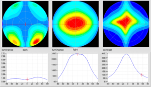
versus viewing direction in a polar coordinate system. The left column shows the directional luminance distribution of the dark state of the display (here: IPS-LCD), the center column shows the bright state and the right column shows the (luminance) contrast (ratio) resulting from the preceding two luminance distributions. The value is coded by (pseudo) colors. The graphs below the polar coordinate systems each show a cross section in the horizontal plane and indicate the values for luminance and for the contrast.
Each borderline between two (shades of) colors represents a line of constant value, in the case of contrast an iso-contrast (contour) line. Note, that "iso" is used here in the sense of "equal", it does NOT establish a relation to the International Organisation for Standardisation, ISO.
This way of representing the variation of a quantity of a display with direction of observation originates from an optical technique called conoscopy
Conoscopy
Conoscopy is an optical technique to make observations of a transparent specimen in a cone of converging rays of light...
. Conoscopy
Conoscopy
Conoscopy is an optical technique to make observations of a transparent specimen in a cone of converging rays of light...
, originally proposed and used by Maugin for examination of the state of liquid crystal
Liquid crystal
Liquid crystals are a state of matter that have properties between those of a conventional liquid and those of a solid crystal. For instance, an LC may flow like a liquid, but its molecules may be oriented in a crystal-like way. There are many different types of LC phases, which can be...
alignment in 1911 has been used in every LCD-laboratory in the late seventies and throughout the eighties for measurement and evaluation of the optical properties of LCDs and for estimation of LCD-contrast as a function of viewing direction. In the conoscopic mode of observation, in the old days often realized with a polarizing microscope
Microscope
A microscope is an instrument used to see objects that are too small for the naked eye. The science of investigating small objects using such an instrument is called microscopy...
, a directions image is generated in the rear focal plane of the objective lens . This directions image is based on the same coordinates as the representation in the polar coordinate system shown in figs. 4 and 5.
The first publication of the variation of the contrast of reflective LCDs measured with a motorized mechanically scanning gonioscopic apparatus and represented as a conoscopic directions figure was published in 1979 .