
Valve RF amplifier
Encyclopedia
A valve RF amplifier or tube amplifier (U.S.
), is a device for electrically amplifying
the power of an electrical signal, typically (but not exclusively) radio frequency signals.
Low to medium power valve amplifiers for frequencies below the microwaves were largely replaced by solid state
amplifiers during the 1960s and 1970s, initially for receivers and low power stages of transmitters, transmitter output stages switching to transistors somewhat later. Specially constructed valves are still in use for very high power transmitters, although rarely in new designs.
s (and especially MOSFET
s) and their transfer characteristics show very flat anode
current vs. anode voltage indicating high anode output impedance
s. Partially correct. Tetrodes and pentodes have "flat" (constant-current) characteristics, but triodes show a strong relationship between anode voltage and anode current.
The high working voltage makes them well suited for radio transmitters, for example, and valves remain in use today for very high power radio transmitters, where there is still no other technology available. However, for most applications requiring an appreciable output current, a matching
transformer
is required. The transformer is a critical component and heavily influences the performance (and cost) of the amplifier.
Many power valves have good open-loop linearity, but only modest gain
or transconductance
. As a result, valve amplifiers usually need only modest levels of feedback. Signal amplifiers using tubes are capable of very high frequency response ranges - up to radio frequency
. Indeed, many of the Directly Heated Single Ended Triode
(DH-SET) audio amplifiers are in fact radio transmitting tubes designed to operate in the megahertz range. In practice, however, tube amplifier designs typically "couple" stages either capacitively, limiting bandwidth at the low end, or inductively with transformers, limiting the bandwidth at high end. Partly correct: output stages almost universally used transformer coupling at the output, a minority use transformer coupling to the input of the output stage. Elsewhere, capacitive coupling (and rarely, direct coupling) is used.
Later development of FM for broadcast rather than communications dramatically changed the design compromise in favour of greater fidelity, accepting that wider bandwidth could be used etc. However technically it becomes more difficult to provide gain bandwidth and linearity at very high frequencies, especially at microwave and above. Confusion: Valve technology suffers high-frequency limitations due to cathode-anode transit time, and this is the principal limiting factor for conventional radio transmitting valves (tetrodes to a few hundred MHz, triodes to a few GHz). It is also unclear why this paragraph has been included - FM broadcast transmissions of 88~108 MHz are generated and transmitted equally well by valve or solid-state devices.
Today's "digital" radio that carries coded data over various phase modulations (such as GMSK, QPSK etc.) and also the increasing demand for spectrum have forced a dramatic change in the way radio is used, e.g. the cellular radio concept. Today's cellular radio standards are extremely demanding in terms of the spectral envelope and out of band emissions that are acceptable (in the case of GSM for example, -70 dB or better just a few hundred kilohertz from center frequency). Increasing the electric acceleration voltage B+ usually reduces electric signal distortion. Increasing negative feedback by increasing the cathode bias resistance Rk also may reduce signal distortion. Relevance? Digital radio equipment will be solid-state, so this passage does not apply in a section on valve amplifiers.
Valve stages were used to amplify the received radio frequency signals, the intermediate frequencies, the video signal and the audio signals at the various points in the receiver. Historically (pre WWII) "transmitting tubes" were among the most powerful tubes available, were usually direct heated by thoriated filaments that glowed like light bulbs. Some tubes were built to be very rugged, capable of being driven so so hard that the anode would itself glow cherry red, the anodes being machined from solid material (rather than fabricated from thin sheet) to be able to withstand this without distorting when heated. Notable tubes of this type are the 845
and 211. Later beam power tubes such as the 807 and (direct heated) 813 were also used in large numbers in (especially military) radio transmitters.
RF circuits are significantly different from broadband circuits.
The antenna or following circuit stage typically contains one or more adjustable capacitive or inductive components allowing (in combinations with one or more fixed capacitive/inductive components) the resonance of the stage to be accurately matched with carrier frequency in use, to optimize power transfer from and loading on the valve: a "tuned circuit"
node
. This circuit is often known as the anode tank circuit.
 An example of this used at VHF/UHF include the 4CX250B, an example of a twin tetrode
is the QQV06/40A.
Neutralization is a term used in valved electronics for negative feedback
which is used to make the system more stable. Negative feedback counteracts the positive feedback in valve circuits. Clarification: it is possible to regard neutralisation as negative feedback that counteracts the positive feedback caused by anode-grid capacitance. "Feedback" is commonly thought of as a means of stablising gain and reducing distortion generally. A more useful concept with R.F. amplifiers is that of a precise balancing of signals to remove the instability effect of A-G capacitance.
It is possible by the correct choice of the ratio of the turns in the inductive
coupling to obtain a step up in drive voltage, allowing a very high gain. However, the high gain increases possible instability and with this type of amplifier, good layout is vital. Comment: while a step-up is possible, it's more common for the previous stage to perform a step-down in voltage and impedance to match the relatively low impedance of valve amplifier's grid, especially if the amplifier operates in Class C and draws appreciable grid current.
In common with all three basic designs shown here, the anode of the valve is connected to a resonant LC circuit which has another inductive coupling which allows the RF signal to be passed to the output.
bias is applied to the valve to ensure that the part of the transfer equation which is most suitable to the required application is used. The input signal is able to perturb (change) the potential of the grid, this in turn will change the anode
current
(also known as the plate current).
In the RF
designs shown on this page, a tuned circuit is between the anode and the high voltage supply. This tuned circuit is brought to resonance presenting an inductive load that is well matched to the valve and thus results in an efficient power transfer.
As the current flowing through the anode connection is controlled by the grid, then the current flowing through the load is also controlled by the grid.
One of the disadvantages of a tuned grid compared to other RF designs is that neutralization is required.
 An example of a passive grid used at VHF/UHF frequencies include the 4CX250B; an example of a twin tetrode would be the QQV06/40A. The tetrode has a screen grid which is between the anode and the first grid, the purpose of which is to increase the stability of the circuit by reducing the capacitance between the first grid and the anode. The combination of the effects of the screen grid and the damping resistor often allow the use of this design without neutralization. Partially incorrect. The QQV06/40A is described by the manufacturer as "internally neutralised". Neutralisation (internal or external) is more commonly used than not used, with "passive grid" being the exception.
The signals come into the circuit through a capacitor, then are applied to the valve's first grid. The value of the grid resistor determines the gain of the amplifier stage. The higher the resistor the greater the gain, the lower the damping effect and the greater the risk of instability. With this type of stage good layout is less vital.
 This design uses a triode, the grid current drawn in this system is larger than that required for the other two basic designs. Because of this, valves such as the 4CX250B are not suitable for this circuit. This circuit design has been used at 1296 MHz using disk seal triode
valves such as the 2C39A.
The grid is kept at ground, the drive is applied to the cathode through a capacitor. The heater supply must be isolated with great care from the cathodes as unlike the other designs the cathode is not connected to RF ground. The cathodes are also at a DC potential more negative than the grounded grid, and the DC supply for the valve is likely to be more complex than the supply required for the other two designs. Incorrect. The grid must be negative with respect to the cathode: if the grid is returned to DC and R.F. ground, the cathode must be made positive to ground so that the grid is negative to the cathode.
For the higher gain designs the positive feedback or negative electric feedback must be counteracted.
Additional screen grids in RF valves reduce the unwanted capacitance between the anode and the first grid. Confusion: is the feedback "positive" or "negative electric"?
 , where kB is the Boltzmann constant and B the bandwidth. Correspondingly, the voltage noise of a resistance R into an open circuit is
  and the current noise into a short circuit is
  .
.
The noise figure is defined as the ratio of the noise power at the output of the amplifier relative to the noise power that would be present at the output if the amplifier were noiseless (due to amplification of thermal noise of the signal source). An equivalent definition is: noise figure is the factor by which insertion of the amplifier degrades the signal to noise ratio. It is often expressed in decibels (dB). An amplifier with a 0 dB noise figure would be perfect.
The noise properties of tubes at audio frequencies can be modelled well by a perfect noiseless tube having a source of voltage noise in series with the grid. For the EF86 tube, for example, this voltage noise is specified (see e.g., the Valvo, Telefunken or Philips data sheets) as 2 microvolts integrated over a frequency range of approximately 25 Hz to 10 kHz. (This refers to the integrated noise, see below for the frequency dependence of the noise spectral density.) This equals the voltage noise of a 25 kΩ resistor. Thus, if the signal source has an impedance of 25 kΩ or more, the noise of the tube is actually smaller than the noise of the source. For a source of 25 kΩ, the noise generated by tube and source are the same, so the total noise power at the output of the amplifier is twice the noise power at the output of the perfect amplifier. The noise figure is then two, or 3 dB. For higher impedances, such as 250 kΩ, the EF86's voltage noise is lower than the sources's own noise. It therefore adds 1/10 of the noise power caused by the source, and the noise figure is 0.4 dB. For a low-impedance source of 250 Ω, on the other hand, the noise voltage contribution of the tube is 10 times larger than the signal source, so that the noise power is one hundred times larger than that caused by the source. The noise figure in this case is 20 dB.
To obtain low noise figure the impedance of the source can be increased by a transformer. This is eventually limited by the input capacity of the tube, which sets a limit on how high the signal impedance can be made if a certain bandwidth is desired.
The noise voltage density of a given tube is a function of frequency. At frequencies above 10 kHz or so, it is basically constant ("white noise"). White noise is often expressed by an equivalent noise resistance, which is defined as the resistance which produces the same voltage noise as present at the tube input. For triodes, it is approximately (2-4)/gm, where gm is the transconductivity. For pentodes, it is higher, about (5-7)/gm. Tubes with high gm thus tend to have lower noise at high frequencies. For example, it is 300 Ω for one half of the ECC88, 250 Ω for an E188CC (both have gm = 12.5 mA/V) and as low as 65 Ω for a tride-connected D3a (gm = 40 mA/V).
In the audio frequency range (below 1–100 kHz), "1/f" noise becomes dominant, which rises like 1/f. (This is the reason for the relatively high noise resistamnce of the EF86 in the above example.) Thus, tubes with low noise at high frequency do not necessarily have low noise in the audio frequency range. For special low noise audio tubes, the frequency at which 1/f noise takes over is reduced as far as possible, maybe to something like a kilohertz. It can be reduced by choosing very pure materials for the cathode nickel, and running the tube at an optimized (generally low) anode current.
At radio frequencies, things are more complicated: (i) The input impedance of a tube has a real component that goes down like 1/f² (due to cathode lead inductance and transit time effects). This means the input impedance can no longer be increased arbitrarily in order to reduce the noise figure. (ii) This input resistance has its own thermal noise, just like any resistor. (The "temperature" of this resistor for noise purposes is more close to the cathode temperature than to room temperature). Thus, the noise figure of tube amplifiers increases with frequency. At 200 MHz, a noise figure of 2.5 (or 4 dB) can be reached with the ECC2000 tube in an optimized "cascode"-circuit with an optimized source impedance. At 800 MHz, tubes like EC8010 have noise figures of about 10 dB or more. Planar triodes are better, but very early, transistors have reached noise figures substantially lower than tubes at UHF. Thus, the tuners of television sets were among the first parts of consumer electronics were transistors were used.
Valve amplifiers remain in some high power applications such as National Terrestrial TV and (VHF) FM radio, also in existing "radar, countermeasures equipment, or communications equipment" (p. 56, Symons .. a reference now a decade old) using specially
designed valves, such as the klystron
, gyrotron
, traveling-wave tube,
and crossed-field amplifier
, however new designs for such products are now invariably semiconductor based.
American English
American English is a set of dialects of the English language used mostly in the United States. Approximately two-thirds of the world's native speakers of English live in the United States....
), is a device for electrically amplifying
Amplifier
Generally, an amplifier or simply amp, is a device for increasing the power of a signal.In popular use, the term usually describes an electronic amplifier, in which the input "signal" is usually a voltage or a current. In audio applications, amplifiers drive the loudspeakers used in PA systems to...
the power of an electrical signal, typically (but not exclusively) radio frequency signals.
Low to medium power valve amplifiers for frequencies below the microwaves were largely replaced by solid state
Solid state (electronics)
Solid-state electronics are those circuits or devices built entirely from solid materials and in which the electrons, or other charge carriers, are confined entirely within the solid material...
amplifiers during the 1960s and 1970s, initially for receivers and low power stages of transmitters, transmitter output stages switching to transistors somewhat later. Specially constructed valves are still in use for very high power transmitters, although rarely in new designs.
Valve characteristics
Valves are high voltage/low current devices in comparison with transistorTransistor
A transistor is a semiconductor device used to amplify and switch electronic signals and power. It is composed of a semiconductor material with at least three terminals for connection to an external circuit. A voltage or current applied to one pair of the transistor's terminals changes the current...
s (and especially MOSFET
MOSFET
The metal–oxide–semiconductor field-effect transistor is a transistor used for amplifying or switching electronic signals. The basic principle of this kind of transistor was first patented by Julius Edgar Lilienfeld in 1925...
s) and their transfer characteristics show very flat anode
Anode
An anode is an electrode through which electric current flows into a polarized electrical device. Mnemonic: ACID ....
current vs. anode voltage indicating high anode output impedance
Electrical impedance
Electrical impedance, or simply impedance, is the measure of the opposition that an electrical circuit presents to the passage of a current when a voltage is applied. In quantitative terms, it is the complex ratio of the voltage to the current in an alternating current circuit...
s. Partially correct. Tetrodes and pentodes have "flat" (constant-current) characteristics, but triodes show a strong relationship between anode voltage and anode current.
The high working voltage makes them well suited for radio transmitters, for example, and valves remain in use today for very high power radio transmitters, where there is still no other technology available. However, for most applications requiring an appreciable output current, a matching
Matching
In the mathematical discipline of graph theory, a matching or independent edge set in a graph is a set of edges without common vertices. It may also be an entire graph consisting of edges without common vertices.- Definition :...
transformer
Transformer
A transformer is a device that transfers electrical energy from one circuit to another through inductively coupled conductors—the transformer's coils. A varying current in the first or primary winding creates a varying magnetic flux in the transformer's core and thus a varying magnetic field...
is required. The transformer is a critical component and heavily influences the performance (and cost) of the amplifier.
Many power valves have good open-loop linearity, but only modest gain
Gain
In electronics, gain is a measure of the ability of a circuit to increase the power or amplitude of a signal from the input to the output. It is usually defined as the mean ratio of the signal output of a system to the signal input of the same system. It may also be defined on a logarithmic scale,...
or transconductance
Transconductance
Transconductance, also known as mutual conductance, is a property of certain electronic components. Conductance is the reciprocal of resistance; transconductance, meanwhile, is the ratio of the current change at the output port to the voltage change at the input port. It is written as gm...
. As a result, valve amplifiers usually need only modest levels of feedback. Signal amplifiers using tubes are capable of very high frequency response ranges - up to radio frequency
Radio frequency
Radio frequency is a rate of oscillation in the range of about 3 kHz to 300 GHz, which corresponds to the frequency of radio waves, and the alternating currents which carry radio signals...
. Indeed, many of the Directly Heated Single Ended Triode
Triode
A triode is an electronic amplification device having three active electrodes. The term most commonly applies to a vacuum tube with three elements: the filament or cathode, the grid, and the plate or anode. The triode vacuum tube was the first electronic amplification device...
(DH-SET) audio amplifiers are in fact radio transmitting tubes designed to operate in the megahertz range. In practice, however, tube amplifier designs typically "couple" stages either capacitively, limiting bandwidth at the low end, or inductively with transformers, limiting the bandwidth at high end. Partly correct: output stages almost universally used transformer coupling at the output, a minority use transformer coupling to the input of the output stage. Elsewhere, capacitive coupling (and rarely, direct coupling) is used.
Circuit advantages of valves
- Very linear (especially triodes) making it viable to use them in low distortion linear circuits with little or no negative feedback
- Extremely high input impedance (cf bipolar transistors but a characteristic shared by FETs)
- Valves are high voltage devices and thus inherently suitable for very high voltage circuits.
- Valves can be constructed on a scale that can dissipate large amounts of heat (some extreme devices even being water cooled). For this reason valves remained the only viable technology for very high power, and especially high power/high voltage applications such as Radio & TV transmitters long into the age when transistors had displaced valves in most other applications. However today these also are increasingly obsolete
- Electrically very robust, they can tolerate overloads which would destroy bipolar transistorBipolar junction transistor|- align = "center"| || PNP|- align = "center"| || NPNA bipolar transistor is a three-terminal electronic device constructed of doped semiconductor material and may be used in amplifying or switching applications. Bipolar transistors are so named because their operation involves both electrons...
systems in millisecondMillisecondA millisecond is a thousandth of a second.10 milliseconds are called a centisecond....
s (of particular significance in military and other "strategically important" systems). Usually lasts longer than transistorized circuits. A transistorized oscilloscope may last 10 to 15 years while a tube driven one much longer. - High electric signal sensitivity or power gain. In some regenerative receivers, a single valve tube may do the work of 5 transistors.
Disadvantages of valves
- Cost
- HeaterHeaterA heater is an object that emits heat or causes another body to achieve a higher temperature. In a household or domestic setting, heaters are usually appliances whose purpose is to generate heating...
supplies are required for the cathodeCathodeA cathode is an electrode through which electric current flows out of a polarized electrical device. Mnemonic: CCD .Cathode polarity is not always negative...
s - Dangerously high voltages are required for the anodes
- High impedance / low current output unsuitable for direct drive of many real world loads, notably various form of electric motor
- Valves may have a shorter working life than solid state parts due to various failure mechanisms (cathode poisoning, breakages (i.e. open circuit) or shorts internally, notably of the heater or grid structures, or in the case of glass valves, physical breakage, although this should not be overstated : many valve types typically have operation lives of the tens of thousands of hours and an indefinite shelf life (many 60 year old tubes are still in regular use), and in worst case a failed tube can simply be unplugged and replaced by a user, cf a failed transistor which normally destroys the entire product beyond economic repair.
- Compared to transistors, valves have the disadvantage of being available in a single polarity only. In most processes transistors are available in complementary polarities (e.g., NPN/PNP), making possible many circuit configurations that cannot be realized with valves.
Distortion
Historic radio techniques were much simpler than those used today. Early communications equipment was optimised for maximum power output (and thus range) from the simplest possible circuitry, and Class C was often used, at the expense of generating extremely high levels of distortion and consequent sidebands, and is now historic interest only. Confusion: Distortion produced by Class C operation creates harmonic energy - extra signal components that are integer multiples of the signal frequency and are undesirable. These are removed by tuned-circuit or bandpass filters. Sidebands are produced by modulation of a power amplifer to impress sound/vision/data onto the carrier, and sidebands are vital and desired components of a transmitted signal. Sidebands will fall within the acceptable passband of the transmitter's allocated frequency channel. These pass through any tuned circuits or filters.Later development of FM for broadcast rather than communications dramatically changed the design compromise in favour of greater fidelity, accepting that wider bandwidth could be used etc. However technically it becomes more difficult to provide gain bandwidth and linearity at very high frequencies, especially at microwave and above. Confusion: Valve technology suffers high-frequency limitations due to cathode-anode transit time, and this is the principal limiting factor for conventional radio transmitting valves (tetrodes to a few hundred MHz, triodes to a few GHz). It is also unclear why this paragraph has been included - FM broadcast transmissions of 88~108 MHz are generated and transmitted equally well by valve or solid-state devices.
Today's "digital" radio that carries coded data over various phase modulations (such as GMSK, QPSK etc.) and also the increasing demand for spectrum have forced a dramatic change in the way radio is used, e.g. the cellular radio concept. Today's cellular radio standards are extremely demanding in terms of the spectral envelope and out of band emissions that are acceptable (in the case of GSM for example, -70 dB or better just a few hundred kilohertz from center frequency). Increasing the electric acceleration voltage B+ usually reduces electric signal distortion. Increasing negative feedback by increasing the cathode bias resistance Rk also may reduce signal distortion. Relevance? Digital radio equipment will be solid-state, so this passage does not apply in a section on valve amplifiers.
Historic transmitters and receivers
(High voltage / High power)Valve stages were used to amplify the received radio frequency signals, the intermediate frequencies, the video signal and the audio signals at the various points in the receiver. Historically (pre WWII) "transmitting tubes" were among the most powerful tubes available, were usually direct heated by thoriated filaments that glowed like light bulbs. Some tubes were built to be very rugged, capable of being driven so so hard that the anode would itself glow cherry red, the anodes being machined from solid material (rather than fabricated from thin sheet) to be able to withstand this without distorting when heated. Notable tubes of this type are the 845
845 (vacuum tube)
The 845 power triode is a radio transmitting vacuum tube which can also be used as an audio amplifier and modulation tube. Typically, the plate is machined from solid graphite in order to accommodate high current dissipation and voltage...
and 211. Later beam power tubes such as the 807 and (direct heated) 813 were also used in large numbers in (especially military) radio transmitters.
Modern narrow band RF / tuned amplifiers
Today, radio transmitters are overwhelmingly silicon based, even at microwave frequencies (notably consider cellular radio base stations). However, while an ever decreasing minority of especially high power radio frequency amplifiers continue to have valve construction, the development of radio is inseparable from valve technology and so this field remains of great historic interest.RF circuits are significantly different from broadband circuits.
- Historically, distortion and out of band emission was less of an issue and Class C sound be used
- Broadband circuits often go down to near DC (10 Hz or below) and up to tens or hundreds of kilohertz / low megahertz, and are required to have essentially flat frequency response over this entire range (4 or more orders of magnitude). RF circuits by contrast are typically required to operate over higher frequencies (which makes capacitive and inductive parasitic effects much more of a design challenge) but often a very narrow frequency range. For example, an RF device might be required to operate over the range 144 to 146 MHz (just 1.4% of an octave)
The antenna or following circuit stage typically contains one or more adjustable capacitive or inductive components allowing (in combinations with one or more fixed capacitive/inductive components) the resonance of the stage to be accurately matched with carrier frequency in use, to optimize power transfer from and loading on the valve: a "tuned circuit"
Radio circuits
Unlike audio amplifiers, in which the analog output signal is of the same form and frequency as the input signal, RF circuits usually modulate the signal onto a carrier (at a much higher frequency), and the circuitry comprises several distinct stages, for example a "radio transmitter" or receiver will contain- an audio frequency (AF) stage (typically using conventional broadband small signal circuitry as described in Valve audio amplifierValve audio amplifierA valve audio amplifier or vacuum tube audio amplifier is a valve amplifier used for sound reinforcement, sound recording and reproduction....
, - one or more oscillator stages that generate the carrier frequency
- one or more mixerMixerMixer may refer to:An electronics device:* DJ mixer, a type of audio mixing console used by disc jockeys* Electronic mixer, a device for adding or multiplying signal voltages together...
stages that (de)modulate sign signal from the carrier, - the baseband stage itself operating at (typically) very high frequency. the TransmitterTransmitterIn electronics and telecommunications a transmitter or radio transmitter is an electronic device which, with the aid of an antenna, produces radio waves. The transmitter itself generates a radio frequency alternating current, which is applied to the antenna. When excited by this alternating...
(baseband) power amp itself is the only high power stage in a radio system, and operates at the carrier (baseband) frequency and is usually a tuned circuit. Confusion: the modulating audio signal is the baseband signal.
Transmitter baseband anode circuits
The most common anode circuit is a tuned LC circuit where the anodes are connected at a voltageVoltage
Voltage, otherwise known as electrical potential difference or electric tension is the difference in electric potential between two points — or the difference in electric potential energy per unit charge between two points...
node
Node (circuits)
In electrical engineering, node refers to any point on a circuit where two or more circuit elements meet. For two nodes to be different, their voltages must be different. Without any further knowledge, it is easy to establish how to find a node by using Ohm's Law: V=IR. When looking at circuit...
. This circuit is often known as the anode tank circuit.
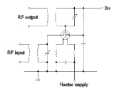
Active (or tuned grid) amplifier
Tetrode
A tetrode is an electronic device having four active electrodes. The term most commonly applies to a two-grid vacuum tube. It has the three electrodes of a triode and an additional screen grid which significantly changes its behaviour.-Control grid:...
is the QQV06/40A.
Neutralization is a term used in valved electronics for negative feedback
Negative feedback
Negative feedback occurs when the output of a system acts to oppose changes to the input of the system, with the result that the changes are attenuated. If the overall feedback of the system is negative, then the system will tend to be stable.- Overview :...
which is used to make the system more stable. Negative feedback counteracts the positive feedback in valve circuits. Clarification: it is possible to regard neutralisation as negative feedback that counteracts the positive feedback caused by anode-grid capacitance. "Feedback" is commonly thought of as a means of stablising gain and reducing distortion generally. A more useful concept with R.F. amplifiers is that of a precise balancing of signals to remove the instability effect of A-G capacitance.
It is possible by the correct choice of the ratio of the turns in the inductive
Inductance
In electromagnetism and electronics, inductance is the ability of an inductor to store energy in a magnetic field. Inductors generate an opposing voltage proportional to the rate of change in current in a circuit...
coupling to obtain a step up in drive voltage, allowing a very high gain. However, the high gain increases possible instability and with this type of amplifier, good layout is vital. Comment: while a step-up is possible, it's more common for the previous stage to perform a step-down in voltage and impedance to match the relatively low impedance of valve amplifier's grid, especially if the amplifier operates in Class C and draws appreciable grid current.
In common with all three basic designs shown here, the anode of the valve is connected to a resonant LC circuit which has another inductive coupling which allows the RF signal to be passed to the output.
Operation
The anode current is controlled by the electrical potential (voltage) of the first grid. A DCDirect current
Direct current is the unidirectional flow of electric charge. Direct current is produced by such sources as batteries, thermocouples, solar cells, and commutator-type electric machines of the dynamo type. Direct current may flow in a conductor such as a wire, but can also flow through...
bias is applied to the valve to ensure that the part of the transfer equation which is most suitable to the required application is used. The input signal is able to perturb (change) the potential of the grid, this in turn will change the anode
Anode
An anode is an electrode through which electric current flows into a polarized electrical device. Mnemonic: ACID ....
current
Electric current
Electric current is a flow of electric charge through a medium.This charge is typically carried by moving electrons in a conductor such as wire...
(also known as the plate current).
In the RF
Radio frequency
Radio frequency is a rate of oscillation in the range of about 3 kHz to 300 GHz, which corresponds to the frequency of radio waves, and the alternating currents which carry radio signals...
designs shown on this page, a tuned circuit is between the anode and the high voltage supply. This tuned circuit is brought to resonance presenting an inductive load that is well matched to the valve and thus results in an efficient power transfer.
As the current flowing through the anode connection is controlled by the grid, then the current flowing through the load is also controlled by the grid.
One of the disadvantages of a tuned grid compared to other RF designs is that neutralization is required.
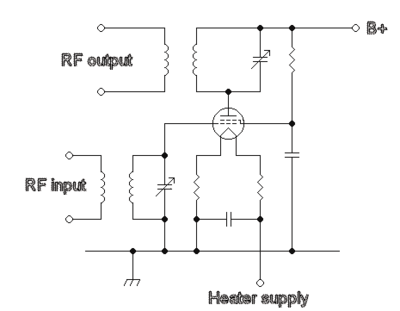
Passive grid amplifier
The signals come into the circuit through a capacitor, then are applied to the valve's first grid. The value of the grid resistor determines the gain of the amplifier stage. The higher the resistor the greater the gain, the lower the damping effect and the greater the risk of instability. With this type of stage good layout is less vital.
Disadvantages
- Low gain, more input power is required
- Less gain than tuned grid
- Less filtering than tuned grid (more broadband), hence the amplification of out of band spurious signals, such as harmonics, from an exciter is greater
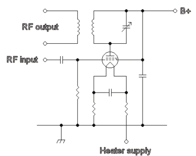
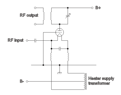
Grounded grid amplifier
Triode
A triode is an electronic amplification device having three active electrodes. The term most commonly applies to a vacuum tube with three elements: the filament or cathode, the grid, and the plate or anode. The triode vacuum tube was the first electronic amplification device...
valves such as the 2C39A.
The grid is kept at ground, the drive is applied to the cathode through a capacitor. The heater supply must be isolated with great care from the cathodes as unlike the other designs the cathode is not connected to RF ground. The cathodes are also at a DC potential more negative than the grounded grid, and the DC supply for the valve is likely to be more complex than the supply required for the other two designs. Incorrect. The grid must be negative with respect to the cathode: if the grid is returned to DC and R.F. ground, the cathode must be made positive to ground so that the grid is negative to the cathode.
Advantages
- Stable, no neutralizing required normally
- Some of the power from exciting stage appears in the output
Disadvantages
- Very low gain, much more input power is required
- The heater must be isolated with greater care from the valve with chokes
Neutralization
The capacitance which exists between the anode and the first grid provides some positive feedback within the valve. This may cause amplifier self oscillation in an amplifier stage.For the higher gain designs the positive feedback or negative electric feedback must be counteracted.
Additional screen grids in RF valves reduce the unwanted capacitance between the anode and the first grid. Confusion: is the feedback "positive" or "negative electric"?
Class C amplifiers
Is very efficient, and was widely used historically, however it generates considerable distortion and wide sidebands. In today's "spectrum scarce" world class C is little used. Class C bias is when the anode current is set just below elecric conduction; meaning the input voltage must reach a specific magnitude before the anode delivers electric current.UHF
Transit time effects are important at these frequencies, so feedback is not normally usable and for performance critical applications alternative linearisation techniques have to be used such as degeneration and feedforward.Tube noise and noise figure
Like any amplifying device, tubes add noise to the signal to be amplified. Even with a hypothetical perfect amplifier, however, noise is unavoidably present due to thermal fluctuations in the signal source (usually assumed to be at room temperature, T = 295 K). Such fluctuations cause an electrical noise power of, where kB is the Boltzmann constant and B the bandwidth. Correspondingly, the voltage noise of a resistance R into an open circuit is and the current noise into a short circuit is .The noise figure is defined as the ratio of the noise power at the output of the amplifier relative to the noise power that would be present at the output if the amplifier were noiseless (due to amplification of thermal noise of the signal source). An equivalent definition is: noise figure is the factor by which insertion of the amplifier degrades the signal to noise ratio. It is often expressed in decibels (dB). An amplifier with a 0 dB noise figure would be perfect.
The noise properties of tubes at audio frequencies can be modelled well by a perfect noiseless tube having a source of voltage noise in series with the grid. For the EF86 tube, for example, this voltage noise is specified (see e.g., the Valvo, Telefunken or Philips data sheets) as 2 microvolts integrated over a frequency range of approximately 25 Hz to 10 kHz. (This refers to the integrated noise, see below for the frequency dependence of the noise spectral density.) This equals the voltage noise of a 25 kΩ resistor. Thus, if the signal source has an impedance of 25 kΩ or more, the noise of the tube is actually smaller than the noise of the source. For a source of 25 kΩ, the noise generated by tube and source are the same, so the total noise power at the output of the amplifier is twice the noise power at the output of the perfect amplifier. The noise figure is then two, or 3 dB. For higher impedances, such as 250 kΩ, the EF86's voltage noise is
lower than the sources's own noise. It therefore adds 1/10 of the noise power caused by the source, and the noise figure is 0.4 dB. For a low-impedance source of 250 Ω, on the other hand, the noise voltage contribution of the tube is 10 times larger than the signal source, so that the noise power is one hundred times larger than that caused by the source. The noise figure in this case is 20 dB.To obtain low noise figure the impedance of the source can be increased by a transformer. This is eventually limited by the input capacity of the tube, which sets a limit on how high the signal impedance can be made if a certain bandwidth is desired.
The noise voltage density of a given tube is a function of frequency. At frequencies above 10 kHz or so, it is basically constant ("white noise"). White noise is often expressed by an equivalent noise resistance, which is defined as the resistance which produces the same voltage noise as present at the tube input. For triodes, it is approximately (2-4)/gm, where gm is the transconductivity. For pentodes, it is higher, about (5-7)/gm. Tubes with high gm thus tend to have lower noise at high frequencies. For example, it is 300 Ω for one half of the ECC88, 250 Ω for an E188CC (both have gm = 12.5 mA/V) and as low as 65 Ω for a tride-connected D3a (gm = 40 mA/V).
In the audio frequency range (below 1–100 kHz), "1/f" noise becomes dominant, which rises like 1/f. (This is the reason for the relatively high noise resistamnce of the EF86 in the above example.) Thus, tubes with low noise at high frequency do not necessarily have low noise in the audio frequency range. For special low noise audio tubes, the frequency at which 1/f noise takes over is reduced as far as possible, maybe to something like a kilohertz. It can be reduced by choosing very pure materials for the cathode nickel, and running the tube at an optimized (generally low) anode current.
At radio frequencies, things are more complicated: (i) The input impedance of a tube has a real component that goes down like 1/f² (due to cathode lead inductance and transit time effects). This means the input impedance can no longer be increased arbitrarily in order to reduce the noise figure. (ii) This input resistance has its own thermal noise, just like any resistor. (The "temperature" of this resistor for noise purposes is more close to the cathode temperature than to room temperature). Thus, the noise figure of tube amplifiers increases with frequency. At 200 MHz, a noise figure of 2.5 (or 4 dB) can be reached with the ECC2000 tube in an optimized "cascode"-circuit with an optimized source impedance. At 800 MHz, tubes like EC8010 have noise figures of about 10 dB or more. Planar triodes are better, but very early, transistors have reached noise figures substantially lower than tubes at UHF. Thus, the tuners of television sets were among the first parts of consumer electronics were transistors were used.
Decline
Semiconductor amplifiers have overwhelmingly displaced valve amplifiers for low and medium power applications at all frequencies.Valve amplifiers remain in some high power applications such as National Terrestrial TV and (VHF) FM radio, also in existing "radar, countermeasures equipment, or communications equipment" (p. 56, Symons .. a reference now a decade old) using specially
designed valves, such as the klystron
Klystron
A klystron is a specialized linear-beam vacuum tube . Klystrons are used as amplifiers at microwave and radio frequencies to produce both low-power reference signals for superheterodyne radar receivers and to produce high-power carrier waves for communications and the driving force for modern...
, gyrotron
Gyrotron
Gyrotrons are high powered vacuum tubes which emit millimeter-wave beams by bunching electrons with cyclotron motion in a strong magnetic field. Output frequencies range from about 20 to 250 GHz, covering wavelengths from microwave to the edge of the terahertz gap. Typical output powers range from...
, traveling-wave tube,
and crossed-field amplifier
Crossed-field amplifier
A crossed-field amplifier is a specialized vacuum tube, first introduced in the mid-1950s and frequently used as a microwave amplifier in very-high-power transmitters....
, however new designs for such products are now invariably semiconductor based.
External links
- http://www.webcitation.org/query?url=http://www.geocities.com/tpsbpl/valvereciver.htm&date=2009-10-25+23:14:07 - AM band (medium wave, short wave) old valve type Radio
- The Audio Circuit - An almost complete list of manufacturers, DIY kits, materials and parts and 'how they work' sections on valve amplifiers
- Conversion calculator - distortion factor to distortion attenuation and THD