Solid state relay
Encyclopedia
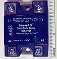
A solid state relay is an electronic switching device in which a small control signal controls a larger load current or voltage. It comprises a voltage or current sensor which responds to an appropriate input (control signal), a solid-state electronic switching device of some kind which switches power to the load circuitry either on or off, and some coupling mechanism to enable the control signal to activate this switch without mechanical parts. The relay may be designed to switch either AC or DC to the load. It serves the same function as an electromechanical relay
, but has no moving parts
.
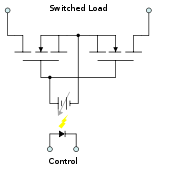
 Many SSRs use optical coupling. The control voltage energizes an LED
which illuminates and switches on a photo-sensitive diode
(photo-voltaic); the diode current turns on a back-to-back thyristor
, silicon controlled rectifier
, or MOSFET
to switch the load. The optical coupling allows the control circuit to be electrically isolated from the load.
There is an inherent substrate diode in all MOSFETs that conducts in the reverse direction. This means that a single MOSFET cannot block current in both directions. For AC (bi-directional) operation two MOSFETs are arranged back to back with their source pins tied together. Their drain pins are connected to either side of the output. The substrate diodes are alternately reverse biased in order to block current when the relay is off. When the relay is on, the common source is always riding on the instantaneous signal level and both gates are biased positive relative to the source by the photo-diode.
It is common to provide access to the common source so that multiple MOSFETs can be wired in parallel if switching a DC load. There is also commonly some circuitry to discharge the gate when the LED is turned off, speeding the relay's turn-off.
(e.g., derating according to thermal resistance when repeatedly switching large currents).
Relay
A relay is an electrically operated switch. Many relays use an electromagnet to operate a switching mechanism mechanically, but other operating principles are also used. Relays are used where it is necessary to control a circuit by a low-power signal , or where several circuits must be controlled...
, but has no moving parts
Moving parts
The moving parts of a machine are those parts of it that move. Machines comprise both moving and fixed parts. The moving parts have controlled and constrained motions....
.
Coupling methods
The control signal must be coupled to the controlled circuit in a way which isolates the two circuits electrically.Optical coupling

LEd
LEd is a TeX/LaTeX editing software working under Microsoft Windows. It is a freeware product....
which illuminates and switches on a photo-sensitive diode
Photodiode
A photodiode is a type of photodetector capable of converting light into either current or voltage, depending upon the mode of operation.The common, traditional solar cell used to generateelectric solar power is a large area photodiode....
(photo-voltaic); the diode current turns on a back-to-back thyristor
Thyristor
A thyristor is a solid-state semiconductor device with four layers of alternating N and P-type material. They act as bistable switches, conducting when their gate receives a current trigger, and continue to conduct while they are forward biased .Some sources define silicon controlled rectifiers and...
, silicon controlled rectifier
Silicon-controlled rectifier
A silicon-controlled rectifier is a four-layer solid state device that controls current. The name "silicon controlled rectifier" or SCR is General Electric's trade name for a type of thyristor. The SCR was developed by a team of power engineers led by Gordon Hall and commercialized by Frank W...
, or MOSFET
MOSFET
The metal–oxide–semiconductor field-effect transistor is a transistor used for amplifying or switching electronic signals. The basic principle of this kind of transistor was first patented by Julius Edgar Lilienfeld in 1925...
to switch the load. The optical coupling allows the control circuit to be electrically isolated from the load.
Operation
An SSR based on a single MOSFET, or multiple MOSFETs in a paralleled array, works well for DC loads.There is an inherent substrate diode in all MOSFETs that conducts in the reverse direction. This means that a single MOSFET cannot block current in both directions. For AC (bi-directional) operation two MOSFETs are arranged back to back with their source pins tied together. Their drain pins are connected to either side of the output. The substrate diodes are alternately reverse biased in order to block current when the relay is off. When the relay is on, the common source is always riding on the instantaneous signal level and both gates are biased positive relative to the source by the photo-diode.
It is common to provide access to the common source so that multiple MOSFETs can be wired in parallel if switching a DC load. There is also commonly some circuitry to discharge the gate when the LED is turned off, speeding the relay's turn-off.
Parameters
The relay is characterised by a number of parameters including the required activating input voltage, current, and whether it is AC or DC; the output voltage and current and whether it is AC or DC, voltage drop or resistance affecting output current, thermal resistance, and thermal and electrical parameters for safe operating areaSafe operating area
For power semiconductor devices , the safe operating area is defined as the voltage and current conditions over which the device can be expected to operate without self-damage....
(e.g., derating according to thermal resistance when repeatedly switching large currents).
Advantages over mechanical relays
Most of the relative advantages of solid state and electromechanical relays are common to all solid-state as against electromechanical devices.- SSRs are faster than electromechanical relays; their switching time is dependent on the time needed to power the LED on and off, of the order of microseconds to milliseconds
- Lower (if any) minimum output current (latching current) required
- Increased lifetime, particularly if activated many times, as there are no moving parts to wear
- Output resistance remains constant regardless of amount of use
- Clean, bounceless operation
- Decreased electrical noise when switching
- No sparking, allowing use in explosive environments where it is critical that no spark is generated during switching
- Totally silent operation
- Inherently smaller than a mechanical relay of similar specification (if desired may have the same "casing" form factor for interchangeability).
- Much less sensitive to storage and operating environmentOperating environmentThe operating environment in engineering describes the circumstances surrounding and potentially affecting something that is operating. For example electronic or mechanical equipment may be affected by high temperatures, vibration, dust, and other parameters which comprise the operating...
factors such as mechanical shockShock (mechanics)A mechanical or physical shock is a sudden acceleration or deceleration caused, for example, by impact, drop, kick, earthquake, or explosion. Shock is a transient physical excitation....
, vibrationVibrationVibration refers to mechanical oscillations about an equilibrium point. The oscillations may be periodic such as the motion of a pendulum or random such as the movement of a tire on a gravel road.Vibration is occasionally "desirable"...
, humidity, and external magnetic fields.
Disadvantages
- Voltage/current characteristic of semiconductor rather than mechanical contacts:
- When closed, higher resistance (generating heat), and increased electrical noise
- When open, lower resistance, and reverse leakage current (typically µA range)
- Voltage/current characteristic is not linear (not purely resistive), distorting switched waveforms to some extent. An electromechanical relay has the low ohmic (linear) resistance of the associated mechanical switch when activated, and the exceedingly high resistance of the air gap and insulating materials when open.
- DC load must observe polarity (- and + not interchangeable) to avoid an undesirable "always conducting" state that does not depend on switching input. Electromechanical relays do not depend on polarity.
- Possibility of spurious switching due to voltage transients (due to much faster switching than mechanical relay)
- Isolated bias supply required for gate charge circuit
- Higher Transient Reverse Recovery time (Trr) due to the presence of Body diode
- More Likely to fail in the "Closed" state compared to Electromechanical relays which are more likely to fail in the "Open" State
Images
 |
 |
 |
|
External links
- Solid State Relays - Selection Guide and Application Tips
- A DC Fault Protection Circuit for Audio Amplifiers
- Solid state relay glossary of terminology
- National Instruments Solid State Relays
- Solid State Relay Inventor and Early PatentsRoy Mankovitz-Overview:Roy Mankovitz has worked as a rocket scientist, lawyer, inventor, entrepreneur nature-based illness prevention researcher, and author...

