

Sequence diagram
Encyclopedia
Unified Modeling Language
Unified Modeling Language is a standardized general-purpose modeling language in the field of object-oriented software engineering. The standard is managed, and was created, by the Object Management Group...
(UML) is a kind of interaction diagram that shows how processes operate with one another and in what order. It is a construct of a Message Sequence Chart
Message Sequence Chart
A Message Sequence Chart is an interaction diagram from the SDL family very similar to UML's sequence diagram, standardized by the International Telecommunication Union....
.
A sequence diagram shows object interactions arranged in time sequence. It depicts the
objects and classes involved in the scenario and the sequence of messages exchanged
between the objects needed to carry out the functionality of the scenario. Sequence
diagrams typically are associated with use case realizations in the Logical View of the
system under development.
Sequence diagrams are sometimes called event diagrams, event scenarios, and timing diagrams.
Overview
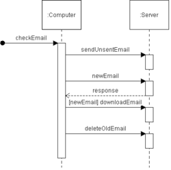
A sequence diagram shows, as parallel vertical lines (lifelines), different processes or objects that live simultaneously, and, as horizontal arrows, the messages exchanged between them, in the order in which they occur. This allows the specification of simple runtime scenarios in a graphical manner.Diagram building blocks
If the lifeline is that of an object, it demonstrates a role. Note that leaving the instance name blank can represent anonymous and unnamed instances.In order to display interaction, messages are used. These are horizontal arrows
Arrow (symbol)
An arrow is a graphical symbol such as → or ←, used to point or indicate direction, being in its simplest form a line segment with a triangle affixed to one end, and in more complex forms a representation of an actual arrow...
with the message name written above them. Solid arrows with full heads are synchronous calls, solid arrows with stick heads are asynchronous calls and dashed arrows with stick heads are return messages. This definition is true as of UML 2, considerably different from UML 1.x .
Activation boxes, or method
Method (computer science)
In object-oriented programming, a method is a subroutine associated with a class. Methods define the behavior to be exhibited by instances of the associated class at program run time...
-call boxes, are opaque rectangles drawn on top of lifelines to represent that processes are being performed in response to the message (ExecutionSpecifications in UML).
Objects calling methods on themselves use messages and add new activation boxes on top of any others to indicate a further level of processing
Process (computing)
In computing, a process is an instance of a computer program that is being executed. It contains the program code and its current activity. Depending on the operating system , a process may be made up of multiple threads of execution that execute instructions concurrently.A computer program is a...
.
When an object is destroyed
Object lifetime
In computer science, the object lifetime of an object in object-oriented programming is the time between an object's creation till the object is no longer used, and is destructed or freed.In object-oriented programming , the meaning of creating objects is far more subtle than simple...
(removed from memory
Computer storage
Computer data storage, often called storage or memory, refers to computer components and recording media that retain digital data. Data storage is one of the core functions and fundamental components of computers....
), an X is drawn on top of the lifeline, and the dashed line ceases to be drawn below it (this is not the case in the first example though). It should be the result of a message, either from the object itself, or another.
A message sent from outside the diagram can be represented by a message originating from a filled-in circle (found message in UML) or from a border of sequence diagram (gate in UML).
UML 2 has introduced significant improvements to the capabilities of sequence diagrams. Most of these improvements are based on the idea of interaction fragments which represent smaller pieces of an enclosing interaction. Multiple interaction fragments are combined to create a variety of combined fragments, which are then used to model interactions that include parallelism, conditional branches, optional interactions.
Usage and limitations
Some systems have simple dynamic behavior that can be expressed in terms of specific sequences of messages between a small, fixed number of objects or processes. In such cases sequence diagrams can completely specify the system's behavior. Often, behavior is more complex, e.g. when the set of communicating objects is large or highly variable, when there are many branch points (e.g. exceptions), when there are complex iterations, or synchronization issues such as resource contention. In such cases, sequence diagrams cannot completely describe the system's behavior, but they can specify typical use caseUse case
In software engineering and systems engineering, a use case is a description of steps or actions between a user and a software system which leads the user towards something useful...
s for the system, small details in its behavior, and simplified overviews of the behavior.
External links
- Current UML Specification by Object Management Group (OMG)Object Management GroupObject Management Group is a consortium, originally aimed at setting standards for distributed object-oriented systems, and is now focused on modeling and model-based standards.- Overview :...
- Introduction to UML 2 Sequence Diagrams by Scott W. Ambler.
- A Quick Introduction to UML Sequence Diagrams by Yanic Inghelbrecht
- UML 2 Sequence Diagrams