
Resistor Ladder
Encyclopedia
A resistor ladder is an electrical circuit made of repeating units of resistors. Two configurations are discussed below, a string resistor ladder and a R-2R ladder.
An R-2R Ladder is a simple and inexpensive way to perform digital-to-analog conversion
, using repetitive arrangements of precision resistor networks in a ladder
-like configuration. A string resistor ladder implements the non-repetitive reference network.
(analog to digital converter). Often a voltage is converted to a current enabling the possibility to use a R-2R ladder network.
between 0 volts and (Vref minus the value of the minimum step, Bit0). The actual value of Vref (and 0 volts) will depend on the type of technology used to generate the digital signals.
For a digital value VAL, of a R-2R DAC of N bits of 0 V/Vref, the output voltage Vout is:
In the example shown, N = 5 and hence 2N = 32. With Vref = 3.3 V (typical CMOS logic 1 voltage), Vout will vary between 00000, VAL = 0 and 11111, VAL = 31.
Minimum (single step) VAL = 1, we have
Maximum output (11111 VAL = 31, we have
The R-2R ladder is inexpensive and relatively easy to manufacture since only two resistor values are required (or 1, if R is made by placing a pair of 2R in parallel, or if 2R is made by placing a pair of R in series). It is fast and has fixed output impedance R. The R-2R ladder operates as a string of current dividers whose output accuracy is solely dependent on how well each resistor is matched to the others. Small inaccuracies in the higher significant bit resistors can entirely overwhelm the contribution of the less significant bits. This may result in non-monotonic behavior at major crossings, such as from 01111 to 10000. Depending on the type of logic gates used and design of the logic circuits, there may be transitional voltage spikes at such major crossings even with perfect resistor values. These can be filtered, with capacitance at the output node for instance (the consequent reduction in bandwidth may be significant in some applications). Finally, the 2R resistance is in series with the digital output impedance. High output impedance gates (e.g., LVDS) may be unsuitable in some cases. For all of the above reasons (and doubtless others), this type of DAC tends to be restricted to a relatively small number of bits, although integrated circuits may push the number of bits to 14 or even more, the home constructor will typically limit themselves to 8 or fewer.
characteristics. Even so, they must often be laser trimmed
to achieve the required precision. Such on-chip
resistor ladders for digital-to-analog converter
s achieving 14 bits accuracy have been demonstrated. On a printed circuit board, using discrete components, high precision resistors of 1% accuracy may be employed for a 5 bit circuit, however with bit counts beyond this the cost of ever increasing precision resistors becomes prohibitive. Often, even for a 5 bit circuit, the home constructor will use either a matched set (by measuring a batch of 100 5% resistors and selecting the best set of 15) or by trimming down individual resistors to a common value (by adding high value resistors in parallel).
resistance of the lower-significance rungs. Figure 2 shows a linear four-bit DAC with unequal resistors.
This allows the home constructor to create a reasonably accurate DAC from a heterogeneous collection of resistors by forming the DAC one bit at a time. At each stage, resistors for the "rung" and "leg" are chosen so that the rung value matches the leg value plus the equivalent resistance of the previous rungs. The rung and leg resistors can be formed by pairing other resistors in series or parallel in order to increase the number of available combinations. This process can be automated.
An R-2R Ladder is a simple and inexpensive way to perform digital-to-analog conversion
Digital-to-analog converter
In electronics, a digital-to-analog converter is a device that converts a digital code to an analog signal . An analog-to-digital converter performs the reverse operation...
, using repetitive arrangements of precision resistor networks in a ladder
Ladder
A ladder is a vertical or inclined set of rungs or steps. There are two types: rigid ladders that can be leaned against a vertical surface such as a wall, and rope ladders that are hung from the top. The vertical members of a rigid ladder are called stringers or stiles . Rigid ladders are usually...
-like configuration. A string resistor ladder implements the non-repetitive reference network.
String resistor ladder network (analog to digital conversion, or ADC)
A string of many, often equally dimensioned, resistors connected between two reference voltages is a resistor string ladder network. The resistors act as voltage dividers between the referenced voltages. Each tap of the string generates a different voltage which can be compared with another voltage: this is the basic principle of a flash ADCFlash ADC
A Flash ADC is a type of analog-to-digital converter that uses a linear voltage ladder with a comparator at each "rung" of the ladder to compare the input voltage to successive reference voltages...
(analog to digital converter). Often a voltage is converted to a current enabling the possibility to use a R-2R ladder network.
- Disadvantage: for a n-bits ADC the number of resistors grows exponentiallyExponential growthExponential growth occurs when the growth rate of a mathematical function is proportional to the function's current value...
, as resistors are required, while the R-2R resistor ladder only increases linearly with the number of bits as it needs only
  resistors.
 - Advantage: Higher impedance values can be reached using the same number of components.
R-2R resistor ladder network (digital to analog conversion, or DAC)
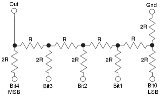
A basic R-2R resistor ladder network is shown in Figure 1. Bit an-1 MSB (most significant bit) to Bit a0 LSB (least significant bit) are driven from digital logic gates. Ideally, the bits are switched between 0 volts (logic 0) and Vref (logic 1). The R-2R network causes the digital bits to be weighted in their contribution to the output voltage Vout. In this circuit 5 bits are shown (bits 4-0), giving (25) or 32 possible analog voltage levels at the output. Depending on which bits are set to 1 and which to 0, the output voltage (out) will be a corresponding stepped valueQuantization (signal processing)
Quantization, in mathematics and digital signal processing, is the process of mapping a large set of input values to a smaller set – such as rounding values to some unit of precision. A device or algorithmic function that performs quantization is called a quantizer. The error introduced by...
between 0 volts and (Vref minus the value of the minimum step, Bit0). The actual value of Vref (and 0 volts) will depend on the type of technology used to generate the digital signals.
For a digital value VAL, of a R-2R DAC of N bits of 0 V/Vref, the output voltage Vout is:
- Vout = Vref × VAL / 2N
In the example shown, N = 5 and hence 2N = 32. With Vref = 3.3 V (typical CMOS logic 1 voltage), Vout will vary between 00000, VAL = 0 and 11111, VAL = 31.
Minimum (single step) VAL = 1, we have
- Vout = 3.3 × 1 / 32 = 0.1 volts
Maximum output (11111 VAL = 31, we have
- Vout = 3.3 × 31 / 25 = 3.2 volts
The R-2R ladder is inexpensive and relatively easy to manufacture since only two resistor values are required (or 1, if R is made by placing a pair of 2R in parallel, or if 2R is made by placing a pair of R in series). It is fast and has fixed output impedance R. The R-2R ladder operates as a string of current dividers whose output accuracy is solely dependent on how well each resistor is matched to the others. Small inaccuracies in the higher significant bit resistors can entirely overwhelm the contribution of the less significant bits. This may result in non-monotonic behavior at major crossings, such as from 01111 to 10000. Depending on the type of logic gates used and design of the logic circuits, there may be transitional voltage spikes at such major crossings even with perfect resistor values. These can be filtered, with capacitance at the output node for instance (the consequent reduction in bandwidth may be significant in some applications). Finally, the 2R resistance is in series with the digital output impedance. High output impedance gates (e.g., LVDS) may be unsuitable in some cases. For all of the above reasons (and doubtless others), this type of DAC tends to be restricted to a relatively small number of bits, although integrated circuits may push the number of bits to 14 or even more, the home constructor will typically limit themselves to 8 or fewer.
Accuracy of R-2R resistor ladders
Resistors used with the more significant bits must be proportionally more accurate than those used with the lower significant bits; for example, in the R-2R network shown above, inaccuracies in the Bit4 MSB resistors must be insignificant compared to R/32 (i.e., much better than 3%). Further, to avoid problems at the 10000 to 01111 transition, the sum of the inaccuracies in the lower bits must be significantly less than R/32. The required accuracy doubles with each additional bit—for 8 bits, the accuracy required will be better than 1/256 (0.4%). Within integrated circuits, high accuracy R-2R networks may be printed directly onto a single substrate using thin-film technology, ensuring the resistors share similar electricalElectricity
Electricity is a general term encompassing a variety of phenomena resulting from the presence and flow of electric charge. These include many easily recognizable phenomena, such as lightning, static electricity, and the flow of electrical current in an electrical wire...
characteristics. Even so, they must often be laser trimmed
Laser trimming
Laser trimming is the manufacturing process of using a laser to adjust the operating parameters of an electronic circuit.One of the most common applications uses a laser to burn away small portions of resistors, raising their resistance value...
to achieve the required precision. Such on-chip
Integrated circuit
An integrated circuit or monolithic integrated circuit is an electronic circuit manufactured by the patterned diffusion of trace elements into the surface of a thin substrate of semiconductor material...
resistor ladders for digital-to-analog converter
Digital-to-analog converter
In electronics, a digital-to-analog converter is a device that converts a digital code to an analog signal . An analog-to-digital converter performs the reverse operation...
s achieving 14 bits accuracy have been demonstrated. On a printed circuit board, using discrete components, high precision resistors of 1% accuracy may be employed for a 5 bit circuit, however with bit counts beyond this the cost of ever increasing precision resistors becomes prohibitive. Often, even for a 5 bit circuit, the home constructor will use either a matched set (by measuring a batch of 100 5% resistors and selecting the best set of 15) or by trimming down individual resistors to a common value (by adding high value resistors in parallel).
Resistor Ladder with Unequal Rungs
It is not necessary that each "rung" of the R-2R ladder use the same resistor values. It is only necessary that the 2R value matches the sum of the R value plus the Thévenin-equivalentThévenin's theorem
In circuit theory, Thévenin's theorem for linear electrical networks states that any combination of voltage sources, current sources, and resistors with two terminals is electrically equivalent to a single voltage source V and a single series resistor R. For single frequency AC systems the theorem...
resistance of the lower-significance rungs. Figure 2 shows a linear four-bit DAC with unequal resistors.
This allows the home constructor to create a reasonably accurate DAC from a heterogeneous collection of resistors by forming the DAC one bit at a time. At each stage, resistors for the "rung" and "leg" are chosen so that the rung value matches the leg value plus the equivalent resistance of the previous rungs. The rung and leg resistors can be formed by pairing other resistors in series or parallel in order to increase the number of available combinations. This process can be automated.
External links
- BI Technologies R2R Resistor Ladder Networks (this reference needs to be re-checked for correctness concerning the variation of the output voltage on the R-2R ladder)
- Digital to Analog converters(DAC), using R/2R networks
- ECE 209: DAC Lecture Notes — Gives short explanation of R-2R ladder with figure showing how currents are divided at each new branch.
- Discussion on R-2R ladders
- Unequal Resistor R-2R Ladder Optimizer