
Radar display
Encyclopedia
Modern radar
systems typically use some sort of raster scan display
to produce a map-like image. In the past, notably during the early days of radar development, such displays were difficult to produce for a number of reasons. Several different display types were developed during this period.
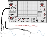
.gif) All early radar displays were built using adapted oscilloscope
All early radar displays were built using adapted oscilloscope
s with various inputs. In a general sense, oscilloscopes are cathode ray tube
s with three input "channels" that are attached to sources of varying voltage. The voltages are amplified and sent into one of the deflection magnets or the "intensity" channel, which controls the brightness of the spot on the screen. All of these channels are also equipped with a bias voltage source that allows the zero point to be set. By varying the voltages sent into the channels, the cathode beam can be made to move around, appearing as a spot on the display.
Radar displays used the output of their radio receivers as one of the channels. In early displays this output was generally sent to either the X or Y channel in order to displace the spot on the screen to indicate a return. More modern radars typically used a rotating or otherwise moving antenna to cover a greater area of the sky, and in these cases the X and Y channels were typically moved by electronics slaved to the mechanical motion of the antenna. The sections below outline the different ways these signals were attached to the channels, and what the resulting display indicated.
display was the A-scope, which displays the range to targets along a scale. These displays were also referred to as R-scope, for range scope.
To draw the A-scope display, a sawtooth voltage generator was attached to the X-axis to move the oscilloscope spot across the screen at a fixed speed. The start of the "sweep" was triggered to coincide with the start of a radar pulse being sent out of the antenna, and the speed of the sweep was set to make it reach the far end (typically right side) of the display at the end of the pulse's maximum return time. Any reflected signal was amplified and sent directly to the display's Y-axis input, displacing the beam upward, drawing a "blip" (or "pip").
Since the pip appeared deflected along the X-axis over time, and the signal's return time corresponded to the distance to the target, the distance of the pip along the X-axis directly indicated the range to the target, and was generally measured against a scale below the display. The size of the blip along the Y-axis gave some indication of the number and size of the targets.
Another version of A-scope was used by early US
and German
radars, the J-scope. These were similar to the A-scope in concept, but were circular and displayed range as an angle around the display face. This arrangement allows greater accuracy in reading the range with the same sized display as an A-scope, since the trace uses the full circumference rather than just the X-axis distance (so the line is π, ~3, times longer). An electro-mechanical version of the J-scope display remained common on consumer boating depth meters
until recently.
The HR-scope was a modified A-scope used by some early radars, notably versions of the Chain Home
system. It displayed the return from two antennas on the same display, with the antennas displaced vertically. By comparing the strength of the two "blips", the elevation could be estimated with some degree of accuracy. The name refers to "height-range".
A similarly modified version of the A-scope display was commonly used for ground-search radars, notably in ASV radars - (Air-Surface Vessel). In this case two receiver antennas were used in front of a common reflector, pointed slightly to the left and right of the aircraft centerline. Reception from both, using lobe switching
, was sent to the left and right sides of a vertically oriented A-scope, and range could be measured as before. However, displacement of the target to the sides of the aircraft would result in the return being stronger on one side than the other, causing the "blip" on that side to be larger. This allowed the radar operator to easily indicate what direction to turn to intercept the target. These types of displays were sometimes referred to as ASV-scopes, although the naming was not universal.
An E-scope is essentially a B-scope displaying range vs. elevation, rather than range vs. azimuth. They are identical in operation to the B-scope, the name simply indicating "elevation". E-scopes are typically used with height finding radars
, which are similar to airborne radars but turned to scan vertically instead of horizontally, they are also sometimes referred to as "nodding radars" due to their antenna's motion. The display tube was generally rotated 90 degrees to put the elevation axis vertical in order to provide a more obvious correlation between the display and the "real world". These displays are also referred to as a Range-Height Indicator, or RHI, but were also commonly referred to (confusingly) as a B-scope as well.
The H-scope is another modification of the B-scope concept, but displays elevation as well as azimuth and range. The elevation information is displayed by drawing a second "blip" offset from the target indicator by a short distance, the slope of the line between the two blips indicates the elevation relative to the radar. For instance, if the blip were displaced directly to the right this would indicate that the target is at the same elevation as the radar. The offset is created by dividing the radio signal into two, then slightly delaying one of the signals so it appears offset on the display. The angle was adjusted by delaying the time of the signal via a delay, the length of the delay being controlled by a voltage varying with the vertical position of the antenna. This sort of elevation display could be added to almost any of the other displays, and was often referred to as a "double dot" display.
Almost identical to the C-scope is the G-scope, which overlays a graphical representation of the range to the target. This is typically represented by a horizontal line that "grows" out from the target indicator "blip" to form a wing-like diagram. The wings grew in length at shorter distances to indicate the target was closer. A "shoot now" range indicator is often supplied as well, typically consisting of two short vertical lines centered on either side of the middle of the display. To make an interception, the pilot guides his aircraft until the blip is centered, then approaches until the "wings" fill the area between the range markers. This display recreated a system commonly used on gunsights, where the pilot would dial in a target's wingspan and then fire when the wings filled the area inside a circle in their sight. This system allowed the pilot to estimate the range to the target. In this case, however, the range is being measured directly by the radar, and the display was mimicking the optical system to retain commonality between the two systems.
until the introduction of raster display
s in the 1990s.
PPI displays are actually quite similar to A-scopes in operation, and appeared fairly quickly after the introduction of radar. As with most 2D radar displays, the output of the radio receiver was attached to the intensity channel to produce a bright dot indicating returns. In the A-scope a sawtooth voltage generator attached to the X-axis moves the spot across the screen, whereas in the PPI the output of two such generators is used to rotate the line around the screen. Some early systems were mechanical, physically spinning the deflection magnets, but the electronics needed to do this in a "solid-state" fashion were not particularly complex, and were in use in the early 1940s.
 The specialist Beta Scan Scope was used for precision approach radar
systems. It displays two lines on the same display, the upper one (typically) displaying the vertical approach (the glideslope), and the lower one the horizontal approach. A marker indicates the desired touchdown point on the runway, and often the lines are angled towards the middle of the screen to indicate this location. A single aircraft's "blip" is also displayed, superimposed over both lines, the signals being generated from separate antennas. Deviation from the centerline of the approach can be seen and easily relayed to the pilot.
Radar
Radar is an object-detection system which uses radio waves to determine the range, altitude, direction, or speed of objects. It can be used to detect aircraft, ships, spacecraft, guided missiles, motor vehicles, weather formations, and terrain. The radar dish or antenna transmits pulses of radio...
systems typically use some sort of raster scan display
Raster graphics
In computer graphics, a raster graphics image, or bitmap, is a data structure representing a generally rectangular grid of pixels, or points of color, viewable via a monitor, paper, or other display medium...
to produce a map-like image. In the past, notably during the early days of radar development, such displays were difficult to produce for a number of reasons. Several different display types were developed during this period.
Oscilloscopes
Oscilloscope
An oscilloscope is a type of electronic test instrument that allows observation of constantly varying signal voltages, usually as a two-dimensional graph of one or more electrical potential differences using the vertical or 'Y' axis, plotted as a function of time,...
s with various inputs. In a general sense, oscilloscopes are cathode ray tube
Cathode ray tube
The cathode ray tube is a vacuum tube containing an electron gun and a fluorescent screen used to view images. It has a means to accelerate and deflect the electron beam onto the fluorescent screen to create the images. The image may represent electrical waveforms , pictures , radar targets and...
s with three input "channels" that are attached to sources of varying voltage. The voltages are amplified and sent into one of the deflection magnets or the "intensity" channel, which controls the brightness of the spot on the screen. All of these channels are also equipped with a bias voltage source that allows the zero point to be set. By varying the voltages sent into the channels, the cathode beam can be made to move around, appearing as a spot on the display.
Radar displays used the output of their radio receivers as one of the channels. In early displays this output was generally sent to either the X or Y channel in order to displace the spot on the screen to indicate a return. More modern radars typically used a rotating or otherwise moving antenna to cover a greater area of the sky, and in these cases the X and Y channels were typically moved by electronics slaved to the mechanical motion of the antenna. The sections below outline the different ways these signals were attached to the channels, and what the resulting display indicated.
A-scope
The original radarRadar
Radar is an object-detection system which uses radio waves to determine the range, altitude, direction, or speed of objects. It can be used to detect aircraft, ships, spacecraft, guided missiles, motor vehicles, weather formations, and terrain. The radar dish or antenna transmits pulses of radio...
display was the A-scope, which displays the range to targets along a scale. These displays were also referred to as R-scope, for range scope.
To draw the A-scope display, a sawtooth voltage generator was attached to the X-axis to move the oscilloscope spot across the screen at a fixed speed. The start of the "sweep" was triggered to coincide with the start of a radar pulse being sent out of the antenna, and the speed of the sweep was set to make it reach the far end (typically right side) of the display at the end of the pulse's maximum return time. Any reflected signal was amplified and sent directly to the display's Y-axis input, displacing the beam upward, drawing a "blip" (or "pip").
Since the pip appeared deflected along the X-axis over time, and the signal's return time corresponded to the distance to the target, the distance of the pip along the X-axis directly indicated the range to the target, and was generally measured against a scale below the display. The size of the blip along the Y-axis gave some indication of the number and size of the targets.
Another version of A-scope was used by early US
United States
The United States of America is a federal constitutional republic comprising fifty states and a federal district...
and German
Germany
Germany , officially the Federal Republic of Germany , is a federal parliamentary republic in Europe. The country consists of 16 states while the capital and largest city is Berlin. Germany covers an area of 357,021 km2 and has a largely temperate seasonal climate...
radars, the J-scope. These were similar to the A-scope in concept, but were circular and displayed range as an angle around the display face. This arrangement allows greater accuracy in reading the range with the same sized display as an A-scope, since the trace uses the full circumference rather than just the X-axis distance (so the line is π, ~3, times longer). An electro-mechanical version of the J-scope display remained common on consumer boating depth meters
Fishfinder
A fishfinder is an instrument used to locate fish underwater by detecting reflected pulses of sound energy, as in SONAR. A modern fishfinder displays measurements of reflected sound on a graphical display, allowing an operator to interpret information to locate schools of fish, underwater debris,...
until recently.
The HR-scope was a modified A-scope used by some early radars, notably versions of the Chain Home
Chain Home
Chain Home was the codename for the ring of coastal Early Warning radar stations built by the British before and during the Second World War. The system otherwise known as AMES Type 1 consisted of radar fixed on top of a radio tower mast, called a 'station' to provide long-range detection of...
system. It displayed the return from two antennas on the same display, with the antennas displaced vertically. By comparing the strength of the two "blips", the elevation could be estimated with some degree of accuracy. The name refers to "height-range".
A similarly modified version of the A-scope display was commonly used for ground-search radars, notably in ASV radars - (Air-Surface Vessel). In this case two receiver antennas were used in front of a common reflector, pointed slightly to the left and right of the aircraft centerline. Reception from both, using lobe switching
Lobe switching
Lobe switching is a method used on early radar sets to improve tracking accuracy. It used two slightly separated antenna elements to send the beam slightly to either side of the midline of the antenna, switching between the two to find which one gave the stronger return, thereby indicating which...
, was sent to the left and right sides of a vertically oriented A-scope, and range could be measured as before. However, displacement of the target to the sides of the aircraft would result in the return being stronger on one side than the other, causing the "blip" on that side to be larger. This allowed the radar operator to easily indicate what direction to turn to intercept the target. These types of displays were sometimes referred to as ASV-scopes, although the naming was not universal.
B-Scope
A B-scope provides a 2-D "top down" representation of space, with the vertical axis typically representing range and the horizontal axis azimuth (angle). B-scope displays were common in airborne radars in the 1950s and 60s, which were mechanically scanned from side to side, and sometimes up and down as well. The B-scope's display represented a horizontal "slice" of the airspace on both sides of the aircraft out to the tracking angles of the radar. The spot was swept up the Y-axis in a fashion similar to the A-scope's X-axis, with distances "up" the display indicating greater range. This signal was mixed with a varying voltage being generated by a mechanical device that depended on the current horizontal angle of the antenna. The result was essentially an A-scope whose range line was rotated to point up, and then rotated back and forth about a zero point at the bottom of the display. The radio signal was sent into the intensity channel, producing a bright spot on the display indicating returns.An E-scope is essentially a B-scope displaying range vs. elevation, rather than range vs. azimuth. They are identical in operation to the B-scope, the name simply indicating "elevation". E-scopes are typically used with height finding radars
Height finder
A height finder is a ground based aircraft altitude measuring device.Early height finder implementations were optical devices and later migrated to radar devices. Devices combining both optics and radar were deployed by the U.S...
, which are similar to airborne radars but turned to scan vertically instead of horizontally, they are also sometimes referred to as "nodding radars" due to their antenna's motion. The display tube was generally rotated 90 degrees to put the elevation axis vertical in order to provide a more obvious correlation between the display and the "real world". These displays are also referred to as a Range-Height Indicator, or RHI, but were also commonly referred to (confusingly) as a B-scope as well.
The H-scope is another modification of the B-scope concept, but displays elevation as well as azimuth and range. The elevation information is displayed by drawing a second "blip" offset from the target indicator by a short distance, the slope of the line between the two blips indicates the elevation relative to the radar. For instance, if the blip were displaced directly to the right this would indicate that the target is at the same elevation as the radar. The offset is created by dividing the radio signal into two, then slightly delaying one of the signals so it appears offset on the display. The angle was adjusted by delaying the time of the signal via a delay, the length of the delay being controlled by a voltage varying with the vertical position of the antenna. This sort of elevation display could be added to almost any of the other displays, and was often referred to as a "double dot" display.
C-Scope
A C-scope displays a "bullseye" view of azimuth vs. elevation. The "blip" was displayed indicating the direction of the target off the centerline axis of the radar, or more commonly, the aircraft or gun it was attached to. They were also known as "moving spot indicators", the moving spot being the target blip. Range is typically displayed separately in these cases, often as a number at the side of the display.Almost identical to the C-scope is the G-scope, which overlays a graphical representation of the range to the target. This is typically represented by a horizontal line that "grows" out from the target indicator "blip" to form a wing-like diagram. The wings grew in length at shorter distances to indicate the target was closer. A "shoot now" range indicator is often supplied as well, typically consisting of two short vertical lines centered on either side of the middle of the display. To make an interception, the pilot guides his aircraft until the blip is centered, then approaches until the "wings" fill the area between the range markers. This display recreated a system commonly used on gunsights, where the pilot would dial in a target's wingspan and then fire when the wings filled the area inside a circle in their sight. This system allowed the pilot to estimate the range to the target. In this case, however, the range is being measured directly by the radar, and the display was mimicking the optical system to retain commonality between the two systems.
Plan Position Indicator
The PPI display provides a 2-D "all round" display of the airspace around a radar site. The distance out from the center of the display indicates range, and the angle around the display is the azimuth to the target. The current position of the radar antenna is typically indicated by a line extending from the center to the outside of the display, which rotates along with the antenna in realtime. It is essentially a B-scope extended to 360 degrees. The PPI display is typically what people think of as a radar display in general, and was widely used in air traffic controlAir traffic control
Air traffic control is a service provided by ground-based controllers who direct aircraft on the ground and in the air. The primary purpose of ATC systems worldwide is to separate aircraft to prevent collisions, to organize and expedite the flow of traffic, and to provide information and other...
until the introduction of raster display
Raster graphics
In computer graphics, a raster graphics image, or bitmap, is a data structure representing a generally rectangular grid of pixels, or points of color, viewable via a monitor, paper, or other display medium...
s in the 1990s.
PPI displays are actually quite similar to A-scopes in operation, and appeared fairly quickly after the introduction of radar. As with most 2D radar displays, the output of the radio receiver was attached to the intensity channel to produce a bright dot indicating returns. In the A-scope a sawtooth voltage generator attached to the X-axis moves the spot across the screen, whereas in the PPI the output of two such generators is used to rotate the line around the screen. Some early systems were mechanical, physically spinning the deflection magnets, but the electronics needed to do this in a "solid-state" fashion were not particularly complex, and were in use in the early 1940s.
Beta Scan Scope
Precision Approach Radar
Precision approach radar is a type of radar guidance system designed to provide lateral and vertical guidance to an aircraft pilot for landing, until the landing threshold is reached. After the aircraft reaches the decision height or decision altitude , guidance is advisory only...
systems. It displays two lines on the same display, the upper one (typically) displaying the vertical approach (the glideslope), and the lower one the horizontal approach. A marker indicates the desired touchdown point on the runway, and often the lines are angled towards the middle of the screen to indicate this location. A single aircraft's "blip" is also displayed, superimposed over both lines, the signals being generated from separate antennas. Deviation from the centerline of the approach can be seen and easily relayed to the pilot.