

M-derived filter
Encyclopedia
m-derived filters or m-type filters are a type of electronic filter
designed using the image
method. They were invented by Otto Zobel in the early 1920s. This filter type was originally intended for use with telephone multiplexing
and was an improvement on the existing constant k type filter
. The main problem being addressed was the need to achieve a better match of the filter into the terminating impedances. In general, all filters designed by the image method fail to give an exact match, but the m-type filter is a big improvement with suitable choice of the parameter m. The m-type filter section has a further advantage in that there is a rapid transition from the cut-off frequency of the pass band to a pole of attenuation
just inside the stop band
. Despite these advantages, there is a drawback with m-type filters; at frequencies past the pole of attenuation, the response starts to rise again, and m-types have poor stop band rejection. For this reason, filters designed using m-type sections are often designed as composite filters
with a mixture of k-type and m-type sections and different values of m at different points to get the optimum performance from both types.
's publication of his constant k-type design in 1922 on which the m-type filter is based. Zobel published the image analysis theory of m-type filters in 1923. Once popular, M-type filters and image parameter designed filters in general are now rarely designed, having been superseded by more advanced network synthesis methods.

 The building block of m-derived filters, as with all image impedance filters, is the "L" network, called a half-section and composed of a series impedance
Z, and a shunt admittance
Y. The m-derived filter is a derivative of the constant k filter
. The starting point of the design is the values of Z and Y derived from the constant k prototype and are given by
where k is the nominal impedance of the filter, or R0. The designer now multiplies Z and Y by an arbitrary constant m (0 < m < 1). There are two different kinds of m-derived section; series and shunt. To obtain the m-derived series half section, the designer determines the impedance that must be added to 1/mY to make the image impedance Z
To obtain the m-derived shunt half section, an admittance is added to 1/mZ to make the image impedance Z
The general arrangements of these circuits are shown in the diagrams to the right along with a specific example of a low pass section.
A consequence of this design is that the m-derived half section will match a k-type section on one side only. Also, an m-type section of one value of m will not match another m-type section of another value of m except on the sides which offer the Z
The pole of attenuation occurs at;
From this it is clear that smaller values of m will produce closer to the cut-off frequency
  and hence will have a sharper cut-off. Despite this cut-off, it also brings the unwanted stop band response of the m-type closer to the cut-off frequency, making it more difficult for this to be filtered with subsequent sections. The value of m chosen is usually a compromise between these conflicting requirements. There is also a practical limit to how small m can be made due to the inherent resistance of the inductors. This has the effect of causing the pole of attenuation to be less deep (that is, it is no longer a genuinely infinite pole) and the slope of cut-off to be less steep. This effect becomes more marked as
  is brought closer to
  , and there ceases to be any improvement in response with an m of about 0.2 or less.
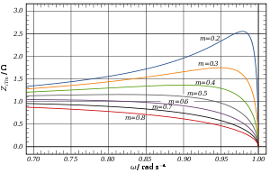 The following expressions for image impedances are all referenced to the low-pass prototype section. They are scaled to the nominal impedance R0 = 1, and the frequencies in those expressions are all scaled to the cut-off frequency ωc = 1.
and is the same as that of the constant k section
and is the same as that of the constant k section
As with the k-type section, the image impedance of the m-type low-pass section is purely real below the cut-off frequency and purely imaginary above it. From the chart it can be seen that in the passband the closest impedance match to a constant pure resistance termination occurs at approximately m = 0.6.
.svg.png) For an m-derived section in general the transmission parameters for a half-section are given by
For an m-derived section in general the transmission parameters for a half-section are given by
and for n half-sections

For the particular example of the low-pass L section, the transmission parameters solve differently in three frequency bands.
For the transmission is lossless:
For the transmission parameters are
For the transmission parameters are
section. The prototype has a cut-off frequency of ωc = 1 rad/s and a nominal impedance R0 = 1 Ω. This is produced by a filter half-section where L = 1 henry and C = 1 farad. This prototype can be impedance scaled and frequency scaled to the desired values. The low-pass prototype can also be transformed into high-pass, band-pass or band-stop types by application of suitable frequency transformations.
. Like impedance must always face like in these combinations. There are therefore two circuits that can be formed with two identical L half-sections. Where Z
It should be born in mind that the characteristics of the filter predicted by the image method are only accurate if the section is terminated with its image impedance. This is usually not true of the sections at either end which are usually terminated with a fixed resistance. The further the section is from the end of the filter, the more accurate the prediction will become since the effects of the terminating impedances are masked by the intervening sections. It is usual to provide half half-sections at the ends of the filter with m = 0.6 as this value gives the flattest Z
Electronic filter
Electronic filters are electronic circuits which perform signal processing functions, specifically to remove unwanted frequency components from the signal, to enhance wanted ones, or both...
designed using the image
Image impedance
Image impedance is a concept used in electronic network design and analysis and most especially in filter design. The term image impedance applies to the impedance seen looking in to the ports of a network. Usually a two-port network is implied but the concept is capable of being extended to...
method. They were invented by Otto Zobel in the early 1920s. This filter type was originally intended for use with telephone multiplexing
Multiplexing
The multiplexed signal is transmitted over a communication channel, which may be a physical transmission medium. The multiplexing divides the capacity of the low-level communication channel into several higher-level logical channels, one for each message signal or data stream to be transferred...
and was an improvement on the existing constant k type filter
Constant k filter
Constant k filters, also k-type filters, are a type of electronic filter designed using the image method. They are the original and simplest filters produced by this methodology and consist of a ladder network of identical sections of passive components...
. The main problem being addressed was the need to achieve a better match of the filter into the terminating impedances. In general, all filters designed by the image method fail to give an exact match, but the m-type filter is a big improvement with suitable choice of the parameter m. The m-type filter section has a further advantage in that there is a rapid transition from the cut-off frequency of the pass band to a pole of attenuation
Attenuation
In physics, attenuation is the gradual loss in intensity of any kind of flux through a medium. For instance, sunlight is attenuated by dark glasses, X-rays are attenuated by lead, and light and sound are attenuated by water.In electrical engineering and telecommunications, attenuation affects the...
just inside the stop band
Stopband
A stopband is a band of frequencies, between specified limits, through which a circuit, such as a filter or telephone circuit, does not allow signals to pass, or the attenuation is above the required stopband attenuation level...
. Despite these advantages, there is a drawback with m-type filters; at frequencies past the pole of attenuation, the response starts to rise again, and m-types have poor stop band rejection. For this reason, filters designed using m-type sections are often designed as composite filters
Composite image filter
A composite image filter is an electronic filter consisting of multiple image filter sections of two or more different types.The image method of filter design determines the properties of filter sections by calculating the properties they have in an infinite chain of such sections. In this, the...
with a mixture of k-type and m-type sections and different values of m at different points to get the optimum performance from both types.
| Midpoint impedance |
| The parameter m is given this symbol because of its association with midpoint impedance, a concept used by Zobel in his original treatment of the subject. Midpoint impedance arises in the following way. In this article and most modern textbooks, the starting point is the simple half-section, and more complex filters are built up from this. In Zobel's treatment and that of his contemporaries, the starting point is always the infinite ladder network. A "mid-series" section is derived by "cutting through the middle" of the series impedance Z and results in a T section. The image impedance ZiT is referred to as the mid-series image impedance. Similarly, a "mid-shunt" section is derived by cutting through the middle of the shunt admittance Y and results in a Π section with a mid-shunt image impedance. A "series m-derived section" is shorthand for "mid-series derived ladder type section". This makes it clear that the word series is referring to the ends of the T section being (half) a series component and not as is sometimes thought, because the additional component is in series with the shunt element. Similarly, "shunt m-derived section" is shorthand for "mid-shunt derived ladder type section". |
Background
Zobel patented an impedance matching network in 1920 which, in essence, used the topology of what are now called m-type filters, but Zobel did not name them as such or analyse them by the image method. This pre-dated George CampbellGeorge Ashley Campbell
George Ashley Campbell was a pioneer in developing and applying quantitative mathematical methods to the problems of long-distance telegraphy and telephony. His most important contributions were to the theory and implementation of the use of loading coils and the first wave filters designed to...
's publication of his constant k-type design in 1922 on which the m-type filter is based. Zobel published the image analysis theory of m-type filters in 1923. Once popular, M-type filters and image parameter designed filters in general are now rarely designed, having been superseded by more advanced network synthesis methods.
Derivation
Electrical impedance
Electrical impedance, or simply impedance, is the measure of the opposition that an electrical circuit presents to the passage of a current when a voltage is applied. In quantitative terms, it is the complex ratio of the voltage to the current in an alternating current circuit...
Z, and a shunt admittance
Admittance
In electrical engineering, the admittance is a measure of how easily a circuit or device will allow a current to flow. It is defined as the inverse of the impedance . The SI unit of admittance is the siemens...
Y. The m-derived filter is a derivative of the constant k filter
Constant k filter
Constant k filters, also k-type filters, are a type of electronic filter designed using the image method. They are the original and simplest filters produced by this methodology and consist of a ladder network of identical sections of passive components...
. The starting point of the design is the values of Z and Y derived from the constant k prototype and are given by

where k is the nominal impedance of the filter, or R0. The designer now multiplies Z and Y by an arbitrary constant m (0 < m < 1). There are two different kinds of m-derived section; series and shunt. To obtain the m-derived series half section, the designer determines the impedance that must be added to 1/mY to make the image impedance Z
iT the same as the image impedance of the original constant k section. From the general formula for image impedance, the additional impedance required can be shown to be
To obtain the m-derived shunt half section, an admittance is added to 1/mZ to make the image impedance Z
iΠ the same as the image impedance of the original half section. The additional admittance required can be shown to be
The general arrangements of these circuits are shown in the diagrams to the right along with a specific example of a low pass section.
A consequence of this design is that the m-derived half section will match a k-type section on one side only. Also, an m-type section of one value of m will not match another m-type section of another value of m except on the sides which offer the Z
i of the k-type.Operating frequency
For the low-pass half section shown, the cut-off frequency of the m-type is the same as the k-type and is given by
The pole of attenuation occurs at;
From this it is clear that smaller values of m will produce
closer to the cut-off frequency and hence will have a sharper cut-off. Despite this cut-off, it also brings the unwanted stop band response of the m-type closer to the cut-off frequency, making it more difficult for this to be filtered with subsequent sections. The value of m chosen is usually a compromise between these conflicting requirements. There is also a practical limit to how small m can be made due to the inherent resistance of the inductors. This has the effect of causing the pole of attenuation to be less deep (that is, it is no longer a genuinely infinite pole) and the slope of cut-off to be less steep. This effect becomes more marked as is brought closer to , and there ceases to be any improvement in response with an m of about 0.2 or less.Image impedance
Series sections
The image impedances of the series section are given by
and is the same as that of the constant k section
Shunt sections
The image impedances of the shunt section are given by
and is the same as that of the constant k section
As with the k-type section, the image impedance of the m-type low-pass section is purely real below the cut-off frequency and purely imaginary above it. From the chart it can be seen that in the passband the closest impedance match to a constant pure resistance termination occurs at approximately m = 0.6.
Transmission parameters
and for n half-sections
For the particular example of the low-pass L section, the transmission parameters solve differently in three frequency bands.
For
the transmission is lossless:
For
the transmission parameters are
For
the transmission parameters are
Prototype transformations
The plots shown of image impedance, attenuation and phase change are the plots of a low-pass prototype filterPrototype filter
Prototype filters are electronic filter designs that are used as a template to produce a modified filter design for a particular application. They are an example of a nondimensionalised design from which the desired filter can be scaled or transformed. They are most often seen in regards to...
section. The prototype has a cut-off frequency of ωc = 1 rad/s and a nominal impedance R0 = 1 Ω. This is produced by a filter half-section where L = 1 henry and C = 1 farad. This prototype can be impedance scaled and frequency scaled to the desired values. The low-pass prototype can also be transformed into high-pass, band-pass or band-stop types by application of suitable frequency transformations.
Cascading sections
Several L half-sections may be cascaded to form a composite filterComposite image filter
A composite image filter is an electronic filter consisting of multiple image filter sections of two or more different types.The image method of filter design determines the properties of filter sections by calculating the properties they have in an infinite chain of such sections. In this, the...
. Like impedance must always face like in these combinations. There are therefore two circuits that can be formed with two identical L half-sections. Where Z
iT faces ZiT, the section is called a Π section. Where ZiΠ faces ZiΠ the section formed is a T section. Further additions of half-sections to either of these forms a ladder network which may start and end with series or shunt elements.It should be born in mind that the characteristics of the filter predicted by the image method are only accurate if the section is terminated with its image impedance. This is usually not true of the sections at either end which are usually terminated with a fixed resistance. The further the section is from the end of the filter, the more accurate the prediction will become since the effects of the terminating impedances are masked by the intervening sections. It is usual to provide half half-sections at the ends of the filter with m = 0.6 as this value gives the flattest Z
i in the passband and hence the best match in to a resistive termination.See also
- Image impedanceImage impedanceImage impedance is a concept used in electronic network design and analysis and most especially in filter design. The term image impedance applies to the impedance seen looking in to the ports of a network. Usually a two-port network is implied but the concept is capable of being extended to...
- Constant k filterConstant k filterConstant k filters, also k-type filters, are a type of electronic filter designed using the image method. They are the original and simplest filters produced by this methodology and consist of a ladder network of identical sections of passive components...
- General mn-type image filtersGeneral mn-type image filtersThese filters are electrical wave filters designed using the image method. They are an invention of Otto Zobel at AT&T Corp.. They are a generalisation of the m-type filter in that a transform is applied that modifies the transfer function while keeping the image impedance unchanged. For filters...
- mm'-type filterMm'-type filtermm'-type filters, also called double-m-derived filters, are a type of electronic filter designed using the image method. They were patented by Otto Zobel in 1932...
- Composite image filterComposite image filterA composite image filter is an electronic filter consisting of multiple image filter sections of two or more different types.The image method of filter design determines the properties of filter sections by calculating the properties they have in an infinite chain of such sections. In this, the...