

Line array
Encyclopedia
A line array is a loudspeaker system that is made up of a number of loudspeaker
elements coupled together in a line segment
to create a near-line source
of sound. The distance between adjacent drivers is close enough that they constructively interfere with each other to send sound waves farther than traditional horn-loaded loudspeakers, and with a more evenly distributed sound output pattern.
Line arrays can be oriented in any direction, but their primary use in public address
is in vertical arrays which provide a very narrow vertical output pattern useful for focusing sound at audiences without wasting output energy on ceilings or empty air above the audience. A vertical line array displays a normally-wide horizontal pattern useful for supplying sound to the majority of a concert
audience. Horizontal line arrays, by contrast, have a very narrow horizontal output pattern and a tall vertical pattern. A row of subwoofer
s along the front edge of a concert stage can behave as a horizontal line array unless the signal supplied to them is adjusted (delayed, polarized, equalized) to shape the pattern otherwise. Loudspeakers can be designed to be arrayed horizontally without behaving as a horizontal line source.
Modern line arrays use separate drivers for high-, mid- and low-frequency passbands. For the line source to work, the drivers in each passband need to be in a line. Therefore, each enclosure must be designed to rig together closely to form columns composed of high-, mid- and low-frequency speaker driver
s. Increasing the number of drivers in each enclosure increases the frequency range and maximum sound pressure level, whilst adding additional boxes to the array will also lower the frequency in which the array achieves a directional dispersion pattern.
The large format line array has become the standard for large concert venues and outdoor festivals, where such systems can be flown (rigged, suspended) from a structural beam, ground support tower or off a tall A-frame truss tower. Since the enclosures rig together and hang from a single point, they are more convenient to assemble and cable than other methods of arraying loudspeakers. The lower portion of the line array is generally curved backward to increase dispersion at the bottom of the array and allow sound to reach more audience members. Typically, cabinets used in line arrays are trapezoidal, connected together by specialized rigging hardware.
 The line array effect of the narrowing of the beam with increasing frequency was first demonstrated by acoustical pioneer Harry Olson
. He published his findings in his 1957 text, Acoustical Engineering. Olson used line array concepts to develop the column speaker in which vertically aligned drivers in a single enclosure produced mid-range output in a wide horizontal and narrow vertical pattern. Line arrays have been around for over half a century but until recently most were voice range only. The application for these were for highly reverberant spaces where a narrow vertical design kept from exciting the reverberant field.
A multi-band line array elements in a horizontally oriented enclosure was suggested by Joseph D'Appolito in 1983. However it was L-Acoustics' V-DOSC line array in the mid-1990s that would show the concert world that a more level and smoother frequency response can come from fewer boxes in a line array. As soon as people realized that there was no destructive interference in the horizontal plane and waves combine mostly in phase in the vertical plane, the race was on for loudspeaker manufacturers.
of the "free field" where sound is free to propagate free of environmental factors such as room reflections or temperature refraction.
In the free field, sound which has its origin at a point (a point source
) will be propagated equally in all directions as a sphere. Since the surface area of a sphere = 4π r² where r is the radius, every doubling of the radius results in a four-fold increase in the sphere's surface area. The result of this is that the sound intensity
quarters for every doubling of distance from the point source. Sound intensity is the acoustic power per unit area, and it decreases as the surface area increases since the acoustic power is spread over a greater area. The ratio between two acoustic pressures in deciBels is expressed by the equation dB = 20log₁₀(P₁/P₀), so for every doubling of distance from the point source P₁ = 4 and P₀ = 1, thus there is an intensity loss of approximately 6 dB.
A line source
is a hypothetical one-dimensional source of sound, as opposed to the dimensionless point source. As a line source propagates sound equally in all directions in the free field, the sound propagates in the shape of a cylinder rather than a sphere. Since the surface area of the curved surface of a cylinder = 2πrh, where r is the radius and h is the height, every doubling of the radius results in a doubling of the surface area, thus the sound intensity halves with each doubling of distance from the line source. Since P₁ = 2 and P₀ = 1 for every distance doubled, this results in a power loss of approximately 3 dB.
In reality, dimensionless point sources and one-dimensional line sources cannot exist, however calculations can be made based on these theoretical models for simplicity. A cone driver, for instance, may have an actual width of 12 inches, but the further a listener is from the driver the more it behaves as a point source as its dimensions become less significant. Thus there is only a certain distance where a line source of a finite length will behave as one - past a certain point, it begins to act more as a point source when its length becomes insignificant. Thus, a true line source has to be infinitely long.
Interference pattern is the term applied to the dispersion pattern of a line array. It means that when you stack a number of loudspeakers vertically, the vertical dispersion angle decreases because the individual drivers are out of phase with each other at listening positions off-axis in the vertical plane. The taller the stack is, the narrower the vertical dispersion will be and the higher the sensitivity will be on-axis. A vertical array of like drivers will have the same horizontal polar pattern as a single driver.
Other than the narrowing vertical coverage, the length of the array also plays a role in what wavelengths will be affected by this narrowing of dispersion. The longer the array, the lower frequency the pattern will control. At frequencies below 100 Hz (wavelength of 11.3 ft) the drivers in a line array will start to become omni-directional, so the system will not conform to line array theory across all frequencies. It is theoretically possible to construct an audio line array that follows the theory at low frequencies. However, the array requires more than 1,000 fifteen-inch drivers, spaced twenty inches center to center, to do it. Above about 400 Hz the low-frequency cones become directional, again violating the theory’s assumptions, and at high frequencies, many practical systems use directional waveguides whose behavior cannot be described using classical line array theory. In short, the geometry of real-world audio line arrays is too complicated to be modeled accurately by ‘pure’ line array theory.
Rather than using constructive and destructive interference, horns achieve directionality by reflecting sound into a specified coverage pattern. In a properly designed line array system, that pattern should closely match the low-frequency directional characteristic of the array. If the array's vertical dispersion is 60 degrees and there are 12 boxes, then each horn would need to have 5 degree vertical coverage. (Narrow vertical coverage has the benefit that it minimizes multiple arrivals, which would harm intelligibility.) If this is achieved, then the wave guide elements can be integrated into the line array and, with proper equalization and crossovers, the beam from the high frequencies and the constructive interference of the low frequencies can be made to align so that the resulting arrayed system provides consistent coverage.
Spiral arrays are the next development from J-arrays, and have a superior frequency response due to their similar polar pattern at shifting frequencies, while still retaining the long throw and in-fill benefits that J-arrays provide. The concept is that spiral arrays are curved all the way along the array, but the curve is progressive. This means that the top of the array is almost straight with angles of 1° between boxes, and increases at the bottom to between 6° and about 10°. A well designed spiral array could have an almost constant directivity pattern with frequency, with some small lobes exhibited at low frequencies.
 Large-format line arrays are designed for large venues or outdoor festivals. These boxes typically included multiple vertically aligned high frequency compression drivers and multiple midrange and low drivers arranged symmetrically around the compression driver. The low frequency driver is typically 15 or 18 inches in diameter. Mid-format line arrays are typically two or three way and use 10 or 12 inch low-frequency drivers. The horizontal coverage is typically 90 degrees wide but some systems employ narrower boxes at the top or wider boxes at the bottom of the array. Using a transition frame (which aligns the rigging on dissimilar systems), system engineers may sometimes hang a mid-format box below a large-format box to cover the closest audience members. Speaker boxes from different manufacturers are not mixed because each system has a particular 'voicing' which may be common to a single manufacturer.
Manufacturers typically provide a spreadsheet or custom program to design arrays. Examples include L-Acoustics SOUNDVISION, Adamson Shooter, Electro-Voice LAPS (Line Array Prediction Software), and JBL Vertec Line Array Calculator. Renkus Heinz offers a program called EaseFocus. It is similar to EASE but has only features and calculations specific to Line arrays. EaseFocus has data for a large number of manufacturers allowing comparison of several loudspeaker systems. Meyer Sound offers a different solution by providing an online system called MAPP Online Pro
The design process starts by entering the dimensions of the room and the required sound pressure level. The program then suggests the number and arrangement of boxes. Alternatively some programs require you to enter the number of boxes and it will predict the resulting sound pressure levels in different parts of the room.
Once designed, the rigging points are hung from the structure, followed by chain motors (or blocks), flying frame and then the speakers. The individual boxes may be connected one at a time or rigged together on the ground and then pulled up. As the array is lifted, individual box angles are adjusted to match the array prediction program. The top frame may have an inclinometer to confirm the angle of the frame or laser attached which indicates the upper aiming point of the array.
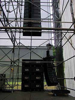
If height or lack of rigging points does not permit flying the speakers, the speakers are typically stacked on the stage or on subwoofers using a custom stacking frame. Stacking of line arrays is common in smaller venues and in temporary installations. Compared to flown speakers, they require less vertical dispersion to cover front to back and the resulting array will have little curvature.
Loudspeaker
A loudspeaker is an electroacoustic transducer that produces sound in response to an electrical audio signal input. Non-electrical loudspeakers were developed as accessories to telephone systems, but electronic amplification by vacuum tube made loudspeakers more generally useful...
elements coupled together in a line segment
Line segment
In geometry, a line segment is a part of a line that is bounded by two end points, and contains every point on the line between its end points. Examples of line segments include the sides of a triangle or square. More generally, when the end points are both vertices of a polygon, the line segment...
to create a near-line source
Line source
A line source is a source of air, noise, water contamination or electromagnetic radiation that emanates from a linear geometry...
of sound. The distance between adjacent drivers is close enough that they constructively interfere with each other to send sound waves farther than traditional horn-loaded loudspeakers, and with a more evenly distributed sound output pattern.
Line arrays can be oriented in any direction, but their primary use in public address
Public address
A public address system is an electronic amplification system with a mixer, amplifier and loudspeakers, used to reinforce a sound source, e.g., a person giving a speech, a DJ playing prerecorded music, and distributing the sound throughout a venue or building.Simple PA systems are often used in...
is in vertical arrays which provide a very narrow vertical output pattern useful for focusing sound at audiences without wasting output energy on ceilings or empty air above the audience. A vertical line array displays a normally-wide horizontal pattern useful for supplying sound to the majority of a concert
Concert
A concert is a live performance before an audience. The performance may be by a single musician, sometimes then called a recital, or by a musical ensemble, such as an orchestra, a choir, or a musical band...
audience. Horizontal line arrays, by contrast, have a very narrow horizontal output pattern and a tall vertical pattern. A row of subwoofer
Subwoofer
A subwoofer is a woofer, or a complete loudspeaker, which is dedicated to the reproduction of low-pitched audio frequencies known as the "bass". The typical frequency range for a subwoofer is about 20–200 Hz for consumer products, below 100 Hz for professional live sound, and below...
s along the front edge of a concert stage can behave as a horizontal line array unless the signal supplied to them is adjusted (delayed, polarized, equalized) to shape the pattern otherwise. Loudspeakers can be designed to be arrayed horizontally without behaving as a horizontal line source.
Modern line arrays use separate drivers for high-, mid- and low-frequency passbands. For the line source to work, the drivers in each passband need to be in a line. Therefore, each enclosure must be designed to rig together closely to form columns composed of high-, mid- and low-frequency speaker driver
Speaker driver
A speaker driver is an individual transducer that converts electrical energy to sound waves, typically as part of a loudspeaker, television, or other electronics device. Sometimes the transducer is itself referred to as a speaker, particularly when a single one is mounted in an enclosure or as...
s. Increasing the number of drivers in each enclosure increases the frequency range and maximum sound pressure level, whilst adding additional boxes to the array will also lower the frequency in which the array achieves a directional dispersion pattern.
The large format line array has become the standard for large concert venues and outdoor festivals, where such systems can be flown (rigged, suspended) from a structural beam, ground support tower or off a tall A-frame truss tower. Since the enclosures rig together and hang from a single point, they are more convenient to assemble and cable than other methods of arraying loudspeakers. The lower portion of the line array is generally curved backward to increase dispersion at the bottom of the array and allow sound to reach more audience members. Typically, cabinets used in line arrays are trapezoidal, connected together by specialized rigging hardware.
History
Harry F. Olson
Harry Ferdinand Olson was a prominent engineer at RCA Victor.Harry F. Olson, a pioneer in the field of 20th century acoustical engineering, was born in Mount Pleasant, Iowa to Swedish immigrant parents...
. He published his findings in his 1957 text, Acoustical Engineering. Olson used line array concepts to develop the column speaker in which vertically aligned drivers in a single enclosure produced mid-range output in a wide horizontal and narrow vertical pattern. Line arrays have been around for over half a century but until recently most were voice range only. The application for these were for highly reverberant spaces where a narrow vertical design kept from exciting the reverberant field.
A multi-band line array elements in a horizontally oriented enclosure was suggested by Joseph D'Appolito in 1983. However it was L-Acoustics' V-DOSC line array in the mid-1990s that would show the concert world that a more level and smoother frequency response can come from fewer boxes in a line array. As soon as people realized that there was no destructive interference in the horizontal plane and waves combine mostly in phase in the vertical plane, the race was on for loudspeaker manufacturers.
Theory
Pure line array theory is based on pure geometry and the thought experimentThought experiment
A thought experiment or Gedankenexperiment considers some hypothesis, theory, or principle for the purpose of thinking through its consequences...
of the "free field" where sound is free to propagate free of environmental factors such as room reflections or temperature refraction.
In the free field, sound which has its origin at a point (a point source
Point source
A point source is a localised, relatively small source of something.Point source may also refer to:*Point source , a localised source of pollution**Point source water pollution, water pollution with a localized source...
) will be propagated equally in all directions as a sphere. Since the surface area of a sphere = 4π r² where r is the radius, every doubling of the radius results in a four-fold increase in the sphere's surface area. The result of this is that the sound intensity
Sound intensity
Sound intensity or acoustic intensity is defined as the sound power Pac per unit area A. The usual context is the noise measurement of sound intensity in the air at a listener's location.-Acoustic intensity:...
quarters for every doubling of distance from the point source. Sound intensity is the acoustic power per unit area, and it decreases as the surface area increases since the acoustic power is spread over a greater area. The ratio between two acoustic pressures in deciBels is expressed by the equation dB = 20log₁₀(P₁/P₀), so for every doubling of distance from the point source P₁ = 4 and P₀ = 1, thus there is an intensity loss of approximately 6 dB.
A line source
Line source
A line source is a source of air, noise, water contamination or electromagnetic radiation that emanates from a linear geometry...
is a hypothetical one-dimensional source of sound, as opposed to the dimensionless point source. As a line source propagates sound equally in all directions in the free field, the sound propagates in the shape of a cylinder rather than a sphere. Since the surface area of the curved surface of a cylinder = 2πrh, where r is the radius and h is the height, every doubling of the radius results in a doubling of the surface area, thus the sound intensity halves with each doubling of distance from the line source. Since P₁ = 2 and P₀ = 1 for every distance doubled, this results in a power loss of approximately 3 dB.
In reality, dimensionless point sources and one-dimensional line sources cannot exist, however calculations can be made based on these theoretical models for simplicity. A cone driver, for instance, may have an actual width of 12 inches, but the further a listener is from the driver the more it behaves as a point source as its dimensions become less significant. Thus there is only a certain distance where a line source of a finite length will behave as one - past a certain point, it begins to act more as a point source when its length becomes insignificant. Thus, a true line source has to be infinitely long.
Interference pattern is the term applied to the dispersion pattern of a line array. It means that when you stack a number of loudspeakers vertically, the vertical dispersion angle decreases because the individual drivers are out of phase with each other at listening positions off-axis in the vertical plane. The taller the stack is, the narrower the vertical dispersion will be and the higher the sensitivity will be on-axis. A vertical array of like drivers will have the same horizontal polar pattern as a single driver.
Other than the narrowing vertical coverage, the length of the array also plays a role in what wavelengths will be affected by this narrowing of dispersion. The longer the array, the lower frequency the pattern will control. At frequencies below 100 Hz (wavelength of 11.3 ft) the drivers in a line array will start to become omni-directional, so the system will not conform to line array theory across all frequencies. It is theoretically possible to construct an audio line array that follows the theory at low frequencies. However, the array requires more than 1,000 fifteen-inch drivers, spaced twenty inches center to center, to do it. Above about 400 Hz the low-frequency cones become directional, again violating the theory’s assumptions, and at high frequencies, many practical systems use directional waveguides whose behavior cannot be described using classical line array theory. In short, the geometry of real-world audio line arrays is too complicated to be modeled accurately by ‘pure’ line array theory.
High frequencies
Practical line array systems act as line sources only in the low- and mid- frequencies. For the high frequencies, some other method must be employed to attain directional characteristics that match those of the lows and mids. The most practical method for reinforcement systems is to use wave guides (horns) coupled to compression drivers. Each horn must have a very narrow vertical and a very wide horizontal dispersion.Rather than using constructive and destructive interference, horns achieve directionality by reflecting sound into a specified coverage pattern. In a properly designed line array system, that pattern should closely match the low-frequency directional characteristic of the array. If the array's vertical dispersion is 60 degrees and there are 12 boxes, then each horn would need to have 5 degree vertical coverage. (Narrow vertical coverage has the benefit that it minimizes multiple arrivals, which would harm intelligibility.) If this is achieved, then the wave guide elements can be integrated into the line array and, with proper equalization and crossovers, the beam from the high frequencies and the constructive interference of the low frequencies can be made to align so that the resulting arrayed system provides consistent coverage.
Configurations
Two configurations that are rarely used are the straight and curved array.The problem with curved arrays is that they are not very well suited to the average venue. While the bottom half will be angled down to provide extra coverage at locations close to the front of stage, the top half will be angled upwards at the ceiling. Also, the problem with straight line arrays is that the beam is far too narrow at high frequencies. A solution to utilise the best features of both arrays is to use a ‘J’ array. This is made up of a straight line portion and a curved portion, normally at the bottom. This provides a long throw straight line component for people relatively far away, while the curve at the bottom acts as an in-fill for the area underneath the array that would otherwise be neglectedSpiral arrays are the next development from J-arrays, and have a superior frequency response due to their similar polar pattern at shifting frequencies, while still retaining the long throw and in-fill benefits that J-arrays provide. The concept is that spiral arrays are curved all the way along the array, but the curve is progressive. This means that the top of the array is almost straight with angles of 1° between boxes, and increases at the bottom to between 6° and about 10°. A well designed spiral array could have an almost constant directivity pattern with frequency, with some small lobes exhibited at low frequencies.
Design and Rigging
Manufacturers typically provide a spreadsheet or custom program to design arrays. Examples include L-Acoustics SOUNDVISION, Adamson Shooter, Electro-Voice LAPS (Line Array Prediction Software), and JBL Vertec Line Array Calculator. Renkus Heinz offers a program called EaseFocus. It is similar to EASE but has only features and calculations specific to Line arrays. EaseFocus has data for a large number of manufacturers allowing comparison of several loudspeaker systems. Meyer Sound offers a different solution by providing an online system called MAPP Online Pro
The design process starts by entering the dimensions of the room and the required sound pressure level. The program then suggests the number and arrangement of boxes. Alternatively some programs require you to enter the number of boxes and it will predict the resulting sound pressure levels in different parts of the room.
Once designed, the rigging points are hung from the structure, followed by chain motors (or blocks), flying frame and then the speakers. The individual boxes may be connected one at a time or rigged together on the ground and then pulled up. As the array is lifted, individual box angles are adjusted to match the array prediction program. The top frame may have an inclinometer to confirm the angle of the frame or laser attached which indicates the upper aiming point of the array.
If height or lack of rigging points does not permit flying the speakers, the speakers are typically stacked on the stage or on subwoofers using a custom stacking frame. Stacking of line arrays is common in smaller venues and in temporary installations. Compared to flown speakers, they require less vertical dispersion to cover front to back and the resulting array will have little curvature.