

Ladder logic
Encyclopedia
Programming language
A programming language is an artificial language designed to communicate instructions to a machine, particularly a computer. Programming languages can be used to create programs that control the behavior of a machine and/or to express algorithms precisely....
that represents a program by a graphical diagram based on the circuit diagram
Circuit diagram
A circuit diagram is a simplified conventional graphical representation of an electrical circuit...
s of relay logic
Relay logic
Relay logic is a method of controlling industrial electronic circuits by using relays and contacts.-Ladder logic:The schematic diagrams for relay logic circuits are often called line diagrams, because the inputs and outputs are essentially drawn in a series of lines...
hardware. It is primarily used to develop software for programmable logic controller
Programmable logic controller
A programmable logic controller or programmable controller is a digital computer used for automation of electromechanical processes, such as control of machinery on factory assembly lines, amusement rides, or light fixtures. PLCs are used in many industries and machines...
s (PLCs) used in industrial control applications. The name is based on the observation that programs in this language resemble ladders, with two vertical rails and a series of horizontal rungs between them.
Overview
An argument that aided the initial adoption of ladder logic was that a wide variety of engineers and technicians would be able to understand and use it without much additional training, because of the resemblance to familiar hardware systems. This argument has become less relevant given that most ladder logic programmers have a software background in more conventional programming languageProgramming language
A programming language is an artificial language designed to communicate instructions to a machine, particularly a computer. Programming languages can be used to create programs that control the behavior of a machine and/or to express algorithms precisely....
s, and in practice implementations of ladder logic have characteristics, such as sequential execution and support for control flow features, that make the analogy to hardware somewhat inaccurate.
Ladder logic is widely used to program PLC
Programmable logic controller
A programmable logic controller or programmable controller is a digital computer used for automation of electromechanical processes, such as control of machinery on factory assembly lines, amusement rides, or light fixtures. PLCs are used in many industries and machines...
s, where sequential control of a process or manufacturing operation is required. Ladder logic is useful for simple but critical control systems or for reworking old hardwired relay circuits. As programmable logic controllers became more sophisticated it has also been used in very complex automation systems. Often the ladder logic program is used in conjunction with an HMI
User interface
The user interface, in the industrial design field of human–machine interaction, is the space where interaction between humans and machines occurs. The goal of interaction between a human and a machine at the user interface is effective operation and control of the machine, and feedback from the...
program operating on a computer workstation.
Manufacturers of programmable logic controllers generally also provide associated ladder logic programming systems. Typically the ladder logic languages from two manufacturers will not be completely compatible; ladder logic is better thought of as a set of closely related programming languages rather than one language. (The IEC 61131-3
IEC 61131-3
IEC 61131-3 is the third part of the open international standard IEC 61131 for programmable logic controllers, and was first published in December 1993 by the IEC...
standard has helped to reduce unnecessary differences, but translating programs between systems still requires significant work.) Even different models of programmable controllers within the same family may have different ladder notation such that programs cannot be seamlessly interchanged between models.
Ladder logic can be thought of as a rule-based language rather than a procedural language. A "rung" in the ladder represents a rule. When implemented with relays and other electromechanical devices, the various rules "execute" simultaneously and immediately. When implemented in a programmable logic controller, the rules are typically executed sequentially by software, in a continuous loop (scan). By executing the loop fast enough, typically many times per second, the effect of simultaneous and immediate execution is relatively achieved to within the tolerance of the time required to execute every rung in the "loop" (the "scan time"). It is somewhat similar to other rule-based languages, like spreadsheet
Spreadsheet
A spreadsheet is a computer application that simulates a paper accounting worksheet. It displays multiple cells usually in a two-dimensional matrix or grid consisting of rows and columns. Each cell contains alphanumeric text, numeric values or formulas...
s or SQL
SQL
SQL is a programming language designed for managing data in relational database management systems ....
. However, proper use of programmable controllers requires understanding the limitations of the execution order of rungs.
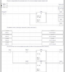
Example of a simple ladder logic program
The language itself can be seen as a set of connections between logical checkers (contacts) and actuators (coils). If a path can be traced between the left side of the rung and the output, through asserted (true or "closed") contacts, the rung is true and the output coil storage bit is asserted (1) or true. If no path can be traced, then the output is false (0) and the "coil" by analogy to electro-mechanical relayRelay
A relay is an electrically operated switch. Many relays use an electromagnet to operate a switching mechanism mechanically, but other operating principles are also used. Relays are used where it is necessary to control a circuit by a low-power signal , or where several circuits must be controlled...
s is considered "de-energized". The analogy between logical propositions and relay contact status is due to Claude Shannon.
Ladder logic has contacts that make or break circuits to control coils. Each coil or contact corresponds to the status of a single bit in the programmable controller's memory. Unlike electromechanical relays, a ladder program can refer any number of times to the status of a single bit, equivalent to a relay with an indefinitely large number of contacts.
So-called "contacts" may refer to physical ("hard") inputs to the programmable controller from physical devices such as pushbuttons and limit switches via an integrated or external input module, or may represent the status of internal storage bits which may be generated elsewhere in the program.
Each rung of ladder language typically has one coil at the far right. Some manufacturers may allow more than one output coil on a rung.
-
——A regular coil, energized whenever its rung is closed. -
—(\)—A "not" coil, energized whenever its rung is open. -
—[ ]—A regular contact, closed whenever its corresponding coil or an input which controls it is energized. -
—[\]—A "not" contact, open whenever its corresponding coil or an input which controls it is energized.
The "coil" (output of a rung) may represent a physical output which operates some device connected to the programmable controller, or may represent an internal storage bit for use elsewhere in the program.
Examples
Here is an example of what one rung in a ladder logic program might look like. In real world applications, there may be hundreds or thousands of rungs.For example:
1. ----[ ]---------|--[ ]--|------
X | Y | S
| |
|--[ ]--|
Z
The above realizes the function: S = X AND ( Y OR Z )
Typically, complex ladder logic is 'read' left to right and top to bottom. As each of the lines (or rungs) are evaluated the output coil of a rung may feed into the next stage of the ladder as an input. In a complex system there will be many "rungs" on a ladder, which are numbered in order of evaluation.
1. ----[ ]-----------|---[ ]---|----
X | Y | S
| |
|---[ ]---|
Z
2. ----[ ]----[ ]-------------------
S X T
2. T = S AND X
This represents a slightly more complex system for rung 2. After the first line has been evaluated, the output coil (S) is fed into rung 2, which is then evaluated and the output coil T could be fed into an output device (buzzer, light etc..) or into rung 3 on the ladder. (Note that the contact X on the second rung serves no useful purpose, as X is already defined in the 'AND' function of S from the 1st rung.)
This system allows very complex logic designs to be broken down and evaluated.
For more practical examples see below:
------[ ]--------------[ ]----------------
Key Switch 1 Key Switch 2 Door Motor
This circuit shows two key switches that security guards might use to activate an electric motor on a bank vault door. When the normally open contacts of both switches close, electricity is able to flow to the motor which opens the door. This is a logical AND.
+-------+
----------------------------+ +----
+-------+
Remote Receiver
--|-------[ ]-------+-----------------
| |
|-------[ ]-------|
Interior Unlock
This circuit shows the two things that can trigger a car's power door locks
Power door locks
Power door locks allow the driver or front passenger to simultaneously lock or unlock all the doors of an automobile or truck, by pressing a button or flipping a switch....
. The remote receiver is always powered. The lock solenoid
Solenoid
A solenoid is a coil wound into a tightly packed helix. In physics, the term solenoid refers to a long, thin loop of wire, often wrapped around a metallic core, which produces a magnetic field when an electric current is passed through it. Solenoids are important because they can create...
gets power when either set of contacts is closed. This is a logical OR.
Often we have a little green "start" button to turn on a motor, and we want to turn it off with a big red "stop" button. The stop button itself is wired as a normally closed switch. This means that when the stop button is in its normal state (not pushed), the PLC input will be true. When the stop button is pushed, the input will go false. This will make the rung false and stop the "run" output. A normally-open contact must be used in the ladder diagram, since this input is normally turned on through the normally closed pushbutton contact, and turns off when the button is pressed.
--+----[ ]--+----[ ]----
| start | stop run
| |
+----[ ]--+
run
-------[ ]--------------
run motor
This latch configuration is a common idiom
Idiom
Idiom is an expression, word, or phrase that has a figurative meaning that is comprehended in regard to a common use of that expression that is separate from the literal meaning or definition of the words of which it is made...
in ladder logic. In ladder logic it is referred to as seal-in logic. The key to understanding the latch is in recognizing that "start" switch is a momentary switch (once the user releases the button, the switch is open again). As soon as the "run" solenoid engages, it closes the "run" switch, which latches the solenoid on. The "start" switch opening up then has no effect.
Additional functionality
Additional functionality can be added to a ladder logic implementation by the PLC manufacturer as a special block. When the special block is powered, it executes code on predetermined arguments. These arguments may be displayed within the special block.+-------+
-----[ ]--------------------+ A +----
Remote Unlock +-------+
Remote Counter
+-------+
-----[ ]--------------------+ B +----
Interior Unlock +-------+
Interior Counter
+--------+
--------------------+ A + B +-----------
+ into C +
+--------+
Adder
In this example, the system will count the number of times that the interior and remote unlock buttons are pressed. This information will be stored in memory locations A and B. Memory location C will hold the total number of times that the door has been unlocked electronically.
PLCs have many types of special blocks. They include timers, arithmetic operators and comparisons, table lookups, text processing, PID
PID controller
A proportional–integral–derivative controller is a generic control loop feedback mechanism widely used in industrial control systems – a PID is the most commonly used feedback controller. A PID controller calculates an "error" value as the difference between a measured process variable and a...
control, and filtering functions. More powerful PLCs can operate on a group of internal memory locations and execute an operation on a range of addresses, for example,to simulate a physical sequential drum controller or a finite state machine
Finite state machine
A finite-state machine or finite-state automaton , or simply a state machine, is a mathematical model used to design computer programs and digital logic circuits. It is conceived as an abstract machine that can be in one of a finite number of states...
. In some cases, users can define their own special blocks, which effectively are subroutines or macros. The large library of special blocks along with high speed execution has allowed use of PLCs to implement very complex automation systems.
Limitations and successor languages
Ladder notation is best suited to control problems where only binary variables are required and where interlocking and sequencing of binary is the primary control problem. Since execution of rungs is sequential within a program and may be undefined or obscure within a rung, some logic race conditionsRace condition
A race condition or race hazard is a flaw in an electronic system or process whereby the output or result of the process is unexpectedly and critically dependent on the sequence or timing of other events...
are possible which may produce unexpected results; complex rungs are best broken into several simpler steps to avoid this problem. Some manufacturers, e.g. Omron
OMRON
is a Japanese electronics company based in Kyoto.Omron was established by Kazuma Tateishi in 1933 and incorporated in 1948. Omron's primary business is the manufacture and sale of automation components, equipment and systems, but it is generally known for medical equipment such as digital...
, avoid this problem by explicitly and completely defining the execution order of a rung, however programmers may still have problems fully grasping the resulting complex semantics.
Analog quantities and arithmetical operations are clumsy to express in ladder logic and each manufacturer has different ways of extending the notation for these problems. There is usually limited support for arrays and loops, often resulting in duplication of code to express cases which in other languages would call for use of indexed variables.
As microprocessors have become more powerful, notations such as sequential function chart
Sequential function chart
Sequential function chart is a graphical programming language used for PLCs. It is one of the five languages defined by IEC 61131-3 standard...
s and function block diagram
Function block diagram
A function block diagram is a block diagram that describes a function between input variables and output variables. A function is described as a set of elementary blocks. Input and output variables are connected to blocks by connection lines...
s can replace ladder logic for some limited applications. Very large programmable controllers may have all or part of the programming carried out in a dialect that resembles BASIC
BASIC
BASIC is a family of general-purpose, high-level programming languages whose design philosophy emphasizes ease of use - the name is an acronym from Beginner's All-purpose Symbolic Instruction Code....
or C
C (programming language)
C is a general-purpose computer programming language developed between 1969 and 1973 by Dennis Ritchie at the Bell Telephone Laboratories for use with the Unix operating system....
or other programming language
Programming language
A programming language is an artificial language designed to communicate instructions to a machine, particularly a computer. Programming languages can be used to create programs that control the behavior of a machine and/or to express algorithms precisely....
with bindings appropriate for a real-time application environment.
External links
- Beginners Ladder Logic Primer
- Basic Ladder Logic
- "Chapter 6: ladder logic" by Tony R. Kuphaldt (Design Science LicenseDesign Science LicenseDesign Science License is a copyleft license for free content such as text, images, music and other content but not for documentation or source code. The DSL was written by Michael Stutz.-External links:*...
); also see "Chapter 10: Multivibrators" (mirror site) - multivibrators
- Ladder Logic Programming Examples
- plc and circuit diagrams
- Logic to Ladder Diagram