

Relay logic
Encyclopedia
Relay logic is a method of controlling industrial electronic circuits by using relays and contacts.
consisting of lines, or rungs, in which each line or rung must have continuity to enable the output device. A typical circuit consists of a number of rungs, with each rung controlling an output. This output is controlled by a combination of input or output conditions, such as input switch
es and control relays. The conditions that represent the inputs are connected in series, parallel, or series-parallel to obtain the logic required to drive the output. The relay logic circuit forms an electrical schematic diagram for the control of input and output devices. Relay logic diagrams represent the physical interconnection of devices. The basic format for relay logic diagrams is as follows:
1. The two vertical lines that connect all devices on the relay logic diagram are labeled L1 and L2. The space between L1 and L2 represents the voltage of the control circuit.
2. Output devices are always connected to L2. Any electrical overload
s that are to be included must be shown between the output device and L2; otherwise, the output device must be the last component before L2.
3. Control devices are always shown between L1 and the output device. Control devices may be connected either in series or in parallel with each other.
4. Devices which perform a STOP function are usually connected in series, while devices that perform a START function are connected in parallel.
5. Electrical devices are shown in their normal conditions. An NC contact would be shown as normally closed, and an NO contact would appear as a normally open device. All contacts associated with a device will change state when the device is energized.
Figure 1 shows a typical relay logic diagram. In this circuit, a STOP/START station is used to control two pilot light
s. When the START button is pressed, the control relay energizes and its associated contacts change state. The green pilot light is now ON and the red lamp is OFF. When the STOP button is pressed, the contacts return to their resting state, the red pilot light is ON, and the green switches OFF.
1. Define the process to be controlled.
2. Draw a sketch
of the operation process. Make sure all the components of the system are present in the drawing.
3. Determine the sequence of operations to be performed. List the sequence of operational steps in as much detail as possible. Write out the sequence in sentences, or put them in table form.
4. Write the relay logic diagram from the sequence of operations.
to ensure conflicting routes can never be selected and helps reduce accidents. Elevator
s are another common application - large relay logic circuits were employed from the 1930s onward to replace the human elevator operator
, but have been progressively superseded with modern solid-state controls in recent years.
 Most relay logic diagrams are in "ladder logic" form.
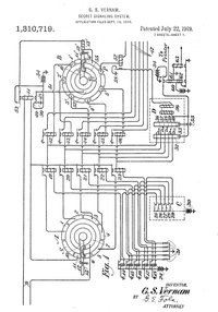
Systems using relay logic diagrams in other forms include the Vernam cipher machine
, the many 20th century telephone exchange
s that controlled their crossbar switch
es by relays, and the designs for the various electro-mechanical computers including the Harvard Mark II
.
Ladder logic
The schematic diagrams for relay logic circuits are often called line diagrams, because the inputs and outputs are essentially drawn in a series of lines. A relay logic circuit is an electrical networkElectrical network
An electrical network is an interconnection of electrical elements such as resistors, inductors, capacitors, transmission lines, voltage sources, current sources and switches. An electrical circuit is a special type of network, one that has a closed loop giving a return path for the current...
consisting of lines, or rungs, in which each line or rung must have continuity to enable the output device. A typical circuit consists of a number of rungs, with each rung controlling an output. This output is controlled by a combination of input or output conditions, such as input switch
Switch
In electronics, a switch is an electrical component that can break an electrical circuit, interrupting the current or diverting it from one conductor to another....
es and control relays. The conditions that represent the inputs are connected in series, parallel, or series-parallel to obtain the logic required to drive the output. The relay logic circuit forms an electrical schematic diagram for the control of input and output devices. Relay logic diagrams represent the physical interconnection of devices. The basic format for relay logic diagrams is as follows:
1. The two vertical lines that connect all devices on the relay logic diagram are labeled L1 and L2. The space between L1 and L2 represents the voltage of the control circuit.
2. Output devices are always connected to L2. Any electrical overload
Overcurrent
In electricity supply, overcurrent or excess current is a situation where a larger than intended electric current exists through a conductor, leading to excessive generation of heat, and the risk of fire or damage to equipment. Possible causes for overcurrent include short circuits, excessive load,...
s that are to be included must be shown between the output device and L2; otherwise, the output device must be the last component before L2.
3. Control devices are always shown between L1 and the output device. Control devices may be connected either in series or in parallel with each other.
4. Devices which perform a STOP function are usually connected in series, while devices that perform a START function are connected in parallel.
5. Electrical devices are shown in their normal conditions. An NC contact would be shown as normally closed, and an NO contact would appear as a normally open device. All contacts associated with a device will change state when the device is energized.
Figure 1 shows a typical relay logic diagram. In this circuit, a STOP/START station is used to control two pilot light
Pilot light
thumb|right|Merker gas fired water heater from the 1930's, with pilot light clearly visible through the aperture in the front cover. The large opening allowed for the manual lighting of the pilot light by a lit match or taper...
s. When the START button is pressed, the control relay energizes and its associated contacts change state. The green pilot light is now ON and the red lamp is OFF. When the STOP button is pressed, the contacts return to their resting state, the red pilot light is ON, and the green switches OFF.
Relay logic design
In many cases, it is possible to design a relay logic diagram directly from the narrative description of a control event sequence. In general, the following suggestions apply to designing a relay logic diagram:1. Define the process to be controlled.
2. Draw a sketch
Sketch (drawing)
A sketch is a rapidly executed freehand drawing that is not usually intended as a finished work...
of the operation process. Make sure all the components of the system are present in the drawing.
3. Determine the sequence of operations to be performed. List the sequence of operational steps in as much detail as possible. Write out the sequence in sentences, or put them in table form.
4. Write the relay logic diagram from the sequence of operations.
Applications
A major application of relay logic is the control of routing and signalling on railways. This safety critical application uses interlockingInterlocking
In railway signalling, an interlocking is an arrangement of signal apparatus that prevents conflicting movements through an arrangement of tracks such as junctions or crossings. The signalling appliances and tracks are sometimes collectively referred to as an interlocking plant...
to ensure conflicting routes can never be selected and helps reduce accidents. Elevator
Elevator
An elevator is a type of vertical transport equipment that efficiently moves people or goods between floors of a building, vessel or other structures...
s are another common application - large relay logic circuits were employed from the 1930s onward to replace the human elevator operator
Elevator operator
An elevator operator is a person specifically employed to operate a manually operated elevator...
, but have been progressively superseded with modern solid-state controls in recent years.
Other kinds of relay logic
Systems using relay logic diagrams in other forms include the Vernam cipher machine
Gilbert Vernam
Gilbert Sandford Vernam was an AT&T Bell Labs engineer who, in 1917, invented the stream cipher and later co-invented the one-time pad cipher. Vernam proposed a teleprinter cipher in which a previously-prepared key, kept on paper tape, is combined character by character with the plaintext message...
, the many 20th century telephone exchange
Telephone exchange
In the field of telecommunications, a telephone exchange or telephone switch is a system of electronic components that connects telephone calls...
s that controlled their crossbar switch
Crossbar switch
In electronics, a crossbar switch is a switch connecting multiple inputs to multiple outputs in a matrix manner....
es by relays, and the designs for the various electro-mechanical computers including the Harvard Mark II
Harvard Mark II
The Harvard Mark II was an electromechanical computer built at Harvard University under the direction of Howard Aiken and was finished in 1947. It was financed by the United States Navy....
.