
Direct stiffness method
Encyclopedia
As one of the methods of structural analysis
, the direct stiffness method (DSM), also known as the displacement method or matrix stiffness method, is particularly suited for computer-automated analysis of complex structures including the statically indeterminate
type. It is a matrix method that makes use of the members' stiffness relations for computing member forces and displacements in structures. The direct stiffness method is the most common implementation of the finite element method
(FEM). In applying the method, the system must be modeled as a set of simpler, idealized elements interconnected at the nodes. The material stiffness properties of these elements are then, through matrix mathematics
, compiled into a single matrix equation which governs the behaviour of the entire idealized structure. The structure’s unknown displacements and forces can then be determined by solving this equation. The direct stiffness method forms the basis for most commercial and free source finite element software.
The direct stiffness method originated in the field of aerospace
. Researchers looked at various approaches for analysis of complex airplane frames. These included elasticity theory, energy principles in structural mechanics
, flexibility method
and matrix stiffness method. It was through analysis of these methods that the direct stiffness method emerged as an efficient method ideally suited for computer implementation.
but publication restrictions from 1938 to 1947 make this work difficult to trace. The second major breakthrough in matrix structural analysis occurred through 1954 and 1955 when professor John H. Argyris systemized the concept of assembling elemental components of a structure into a system of equations. Finally, on Nov. 6 1959, M. J. Turner, head of Boeing
’s Structural Dynamics Unit, published a paper outlining the direct stiffness method as an efficient model for computer implementation .

where
If are member deformations rather than absolute displacements, then
  are independent member forces, and in such case (1) can be inverted to yield the so-called member flexibility matrix, which is used in the flexibility method
.
For a system with many members interconnected at points called nodes, the members' stiffness relations such as Eq.(1) can be integrated by making use of the following observations:

where = vector of nodal forces, representing external forces applied to the system's nodes.
 = system stiffness matrix, which is established by assembling the members' stiffness matrices
  .
. = vector of system's nodal displacements that can define all possible deformed configurations of the system subject to arbitrary nodal forces R.
 = vector of equivalent nodal forces, representing all external effects other than the nodal forces which are already included in the preceding nodal force vector R. This vector is established by assembling the members'
  .
.
 is symmetric. Once the supports' constraints are accounted for in (2), the nodal displacements are found by solving the system of linear equations (2), symbolically:
Subsequently, the members' characteristic forces may be found from Eq.(1) where can be found from r by compatibility consideration.
 and
and  are, respectively, the member-end displacements and forces matching in direction with r and R. In such case,
  and
and  can be obtained by direct summation of the members' matrices
  and
and  . The method is then known as the direct stiffness method.
The advantages and disadvantages of the matrix stiffness method are compared and discussed in the flexibility method
article.
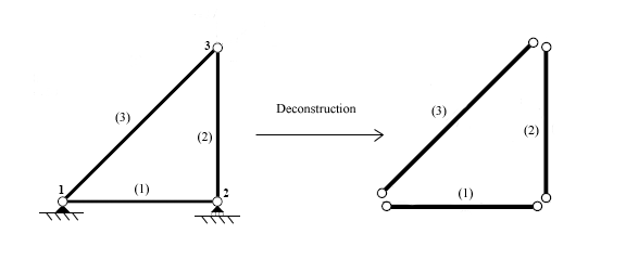
Once the elements are identified, the structure is disconnected at the nodes, the points which connect the different elements together.
Each element is then analyzed individually to develop member stiffness equations. The forces and displacements are related through the element stiffness matrix which depends on the geometry and properties of the element.
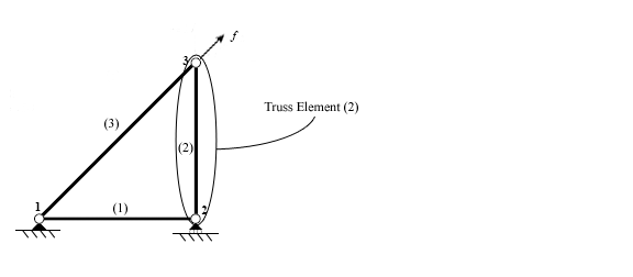
A truss element can only transmit forces in compression or tension. This means that in two dimensions, each node has two degrees of freedom (DOF): horizontal and vertical displacement. The resulting equation contains a four by four stiffness matrix.
A frame element is able to withstand bending moments in addition to compression and tension. This results in three degrees of freedom: horizontal displacement, vertical displacement and in-plane rotation. The stiffness matrix in this case is six by six.
Other elements such as plates and shells can also be incorporated into the direct stiffness method and similar equations must be developed.
).
(for a truss element at angle β)
After developing the element stiffness matrix in the global coordinate system, they must be merged into a single “master” or “global” stiffness matrix. When merging these matrices together there are two rules that must be followed: compatibility of displacements and force equilibrium at each node. These rules are upheld by relating the element nodal displacements to the global nodal displacements.
The global displacement and force vectors each contain one entry for each degree of freedom in the structure. The element stiffness matrices are merged together by augmenting or expanding each matrix in conformation to the global displacement and load vectors.
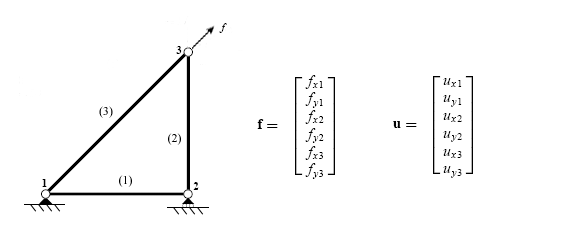
(for element (1) of the above structure)
Finally, the global stiffness matrix is constructed by adding the individual expanded element matrices together.
For each degree of freedom in the structure, either the displacement or the force is known.
After inserting the known value for each degree of freedom, the master stiffness equation is complete and ready to be evaluated. There are several different methods available for evaluating a matrix equation including but not limited to Cholesky decomposition
and the brute force evaluation of systems of equations. If a structure isn’t properly restrained, the application of a force will cause it to move rigidly and additional support conditions must be added.
The method described in this section is meant as an overview of the direct stiffness method. Additional sources should be consulted for more details on the process as well as the assumptions about material properties inherent in the process.
One of the largest areas to utilize the direct stiffness method is the field of structural analysis where this method has been incorporated into modeling software. The software allows users to model a structure and, after the user defines the material properties of the elements, the program automatically generates element and global stiffness relationships. When various loading conditions are applied the software evaluates the structure and generates the deflections for the user.
Structural analysis
Structural analysis is the determination of the effects of loads on physical structures and their components. Structures subject to this type of analysis include all that must withstand loads, such as buildings, bridges, vehicles, machinery, furniture, attire, soil strata, prostheses and...
, the direct stiffness method (DSM), also known as the displacement method or matrix stiffness method, is particularly suited for computer-automated analysis of complex structures including the statically indeterminate
Statically indeterminate
In statics, a structure is statically indeterminate when the static equilibrium equations are insufficient for determining the internal forces and reactions on that structure....
type. It is a matrix method that makes use of the members' stiffness relations for computing member forces and displacements in structures. The direct stiffness method is the most common implementation of the finite element method
Finite element method
The finite element method is a numerical technique for finding approximate solutions of partial differential equations as well as integral equations...
(FEM). In applying the method, the system must be modeled as a set of simpler, idealized elements interconnected at the nodes. The material stiffness properties of these elements are then, through matrix mathematics
Matrix (mathematics)
In mathematics, a matrix is a rectangular array of numbers, symbols, or expressions. The individual items in a matrix are called its elements or entries. An example of a matrix with six elements isMatrices of the same size can be added or subtracted element by element...
, compiled into a single matrix equation which governs the behaviour of the entire idealized structure. The structure’s unknown displacements and forces can then be determined by solving this equation. The direct stiffness method forms the basis for most commercial and free source finite element software.
The direct stiffness method originated in the field of aerospace
Aerospace
Aerospace comprises the atmosphere of Earth and surrounding space. Typically the term is used to refer to the industry that researches, designs, manufactures, operates, and maintains vehicles moving through air and space...
. Researchers looked at various approaches for analysis of complex airplane frames. These included elasticity theory, energy principles in structural mechanics
Energy principles in structural mechanics
Energy principles in structural mechanics express the relationships between stresses, strains or deformations, displacements, material properties, and external effects in the form of energy or work done by internal and external forces...
, flexibility method
Flexibility method
In structural engineering, the flexibility method is the classical consistent deformation method for computing member forces and displacements in structural systems...
and matrix stiffness method. It was through analysis of these methods that the direct stiffness method emerged as an efficient method ideally suited for computer implementation.
History
Between 1934 and 1938 A. R. Collar and W. J. Duncan published the first papers with the representation and terminology for matrix systems that are used today. Aeroelastic research continued through World War IIWorld War II
World War II, or the Second World War , was a global conflict lasting from 1939 to 1945, involving most of the world's nations—including all of the great powers—eventually forming two opposing military alliances: the Allies and the Axis...
but publication restrictions from 1938 to 1947 make this work difficult to trace. The second major breakthrough in matrix structural analysis occurred through 1954 and 1955 when professor John H. Argyris systemized the concept of assembling elemental components of a structure into a system of equations. Finally, on Nov. 6 1959, M. J. Turner, head of Boeing
Boeing
The Boeing Company is an American multinational aerospace and defense corporation, founded in 1916 by William E. Boeing in Seattle, Washington. Boeing has expanded over the years, merging with McDonnell Douglas in 1997. Boeing Corporate headquarters has been in Chicago, Illinois since 2001...
’s Structural Dynamics Unit, published a paper outlining the direct stiffness method as an efficient model for computer implementation .
Member stiffness relations
A typical member stiffness relation has the following general form:where
- m = member number m.
 = vector of member's characteristic forces, which are unknown internal forces.
 = member stiffness matrix which characterises the member's resistance against deformations.
 = vector of member's characteristic displacements or deformations.
 = vector of member's characteristic forces caused by external effects (such as known forces and temperature changes) applied to the member while
  ).
).
If
are member deformations rather than absolute displacements, then are independent member forces, and in such case (1) can be inverted to yield the so-called member flexibility matrix, which is used in the flexibility methodFlexibility method
In structural engineering, the flexibility method is the classical consistent deformation method for computing member forces and displacements in structural systems...
.
System stiffness relation
- See also: Stiffness matrix
For a system with many members interconnected at points called nodes, the members' stiffness relations such as Eq.(1) can be integrated by making use of the following observations:
- The member deformations
 can be expressed in terms of system nodal displacements r in order to ensure compatibility between members. This implies that r will be the primary unknowns.
 - The member forces
 help to the keep the nodes in equilibrium under the nodal forces R. This implies that the right-hand-side of (1) will be integrated into the right-hand-side of the following nodal equilibrium equations for the entire system:
where
= vector of nodal forces, representing external forces applied to the system's nodes. = system stiffness matrix, which is established by assembling the members' stiffness matrices . = vector of system's nodal displacements that can define all possible deformed configurations of the system subject to arbitrary nodal forces R. = vector of equivalent nodal forces, representing all external effects other than the nodal forces which are already included in the preceding nodal force vector R. This vector is established by assembling the members' .Solution
The system stiffness matrix K is square since the vectors R and r have the same size. In addition, it is symmetric because is symmetric. Once the supports' constraints are accounted for in (2), the nodal displacements are found by solving the system of linear equations (2), symbolically:Subsequently, the members' characteristic forces may be found from Eq.(1) where
can be found from r by compatibility consideration.The direct stiffness method
It is common to have Eq.(1) in a form where and are, respectively, the member-end displacements and forces matching in direction with r and R. In such case, and can be obtained by direct summation of the members' matrices and . The method is then known as the direct stiffness method.The advantages and disadvantages of the matrix stiffness method are compared and discussed in the flexibility method
Flexibility method
In structural engineering, the flexibility method is the classical consistent deformation method for computing member forces and displacements in structural systems...
article.
Breakdown
The first step when using the direct stiffness method is to identify the individual elements which make up the structure.Once the elements are identified, the structure is disconnected at the nodes, the points which connect the different elements together.
Each element is then analyzed individually to develop member stiffness equations. The forces and displacements are related through the element stiffness matrix which depends on the geometry and properties of the element.
A truss element can only transmit forces in compression or tension. This means that in two dimensions, each node has two degrees of freedom (DOF): horizontal and vertical displacement. The resulting equation contains a four by four stiffness matrix.
A frame element is able to withstand bending moments in addition to compression and tension. This results in three degrees of freedom: horizontal displacement, vertical displacement and in-plane rotation. The stiffness matrix in this case is six by six.
Other elements such as plates and shells can also be incorporated into the direct stiffness method and similar equations must be developed.
Assembly
Once the individual element stiffness relations have been developed they must be assembled into the original structure. The first step in this process is to convert the stiffness relations for the individual elements into a global system for the entire structure. In the case of a truss element, the global form of the stiffness method depends on the angle of the element with respect to the global coordinate system (This system is usually the traditional Cartesian coordinate systemCartesian coordinate system
A Cartesian coordinate system specifies each point uniquely in a plane by a pair of numerical coordinates, which are the signed distances from the point to two fixed perpendicular directed lines, measured in the same unit of length...
).
(for a truss element at angle β)
After developing the element stiffness matrix in the global coordinate system, they must be merged into a single “master” or “global” stiffness matrix. When merging these matrices together there are two rules that must be followed: compatibility of displacements and force equilibrium at each node. These rules are upheld by relating the element nodal displacements to the global nodal displacements.
The global displacement and force vectors each contain one entry for each degree of freedom in the structure. The element stiffness matrices are merged together by augmenting or expanding each matrix in conformation to the global displacement and load vectors.
(for element (1) of the above structure)
Finally, the global stiffness matrix is constructed by adding the individual expanded element matrices together.
Solution
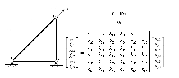
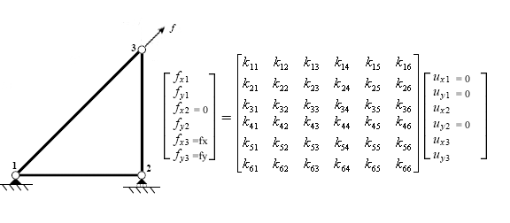
Once the global stiffness matrix, displacement vector and force vector have been constructed, the system can be expressed as a single matrix equation.For each degree of freedom in the structure, either the displacement or the force is known.
After inserting the known value for each degree of freedom, the master stiffness equation is complete and ready to be evaluated. There are several different methods available for evaluating a matrix equation including but not limited to Cholesky decomposition
Cholesky decomposition
In linear algebra, the Cholesky decomposition or Cholesky triangle is a decomposition of a Hermitian, positive-definite matrix into the product of a lower triangular matrix and its conjugate transpose. It was discovered by André-Louis Cholesky for real matrices...
and the brute force evaluation of systems of equations. If a structure isn’t properly restrained, the application of a force will cause it to move rigidly and additional support conditions must be added.
The method described in this section is meant as an overview of the direct stiffness method. Additional sources should be consulted for more details on the process as well as the assumptions about material properties inherent in the process.
Applications
The direct stiffness method was developed specifically to effectively and easily implement into computer software to evaluate complicated structures that contain a large number of elements. Today, nearly every finite element solver available is based on the direct stiffness method. While each program utilizes the same process, many have been streamlined to reduce computation time and reduce the required memory. In order to achieve this, shortcuts have been developed.One of the largest areas to utilize the direct stiffness method is the field of structural analysis where this method has been incorporated into modeling software. The software allows users to model a structure and, after the user defines the material properties of the elements, the program automatically generates element and global stiffness relationships. When various loading conditions are applied the software evaluates the structure and generates the deflections for the user.
See also
- Finite element methodFinite element methodThe finite element method is a numerical technique for finding approximate solutions of partial differential equations as well as integral equations...
- Finite element method in structural mechanicsFinite element method in structural mechanicsThe Finite element method is a powerful technique originally developed for numerical solution of complex problems in structural mechanics, and it remains the method of choice for complex systems. In the FEM, the structural system is modeled by a set of appropriate finite elements interconnected at...
- Structural analysisStructural analysisStructural analysis is the determination of the effects of loads on physical structures and their components. Structures subject to this type of analysis include all that must withstand loads, such as buildings, bridges, vehicles, machinery, furniture, attire, soil strata, prostheses and...
- Flexibility methodFlexibility methodIn structural engineering, the flexibility method is the classical consistent deformation method for computing member forces and displacements in structural systems...
- List of finite element software packages