
.gif)
Attenuator (electronics)
Encyclopedia
Amplitude
Amplitude is the magnitude of change in the oscillating variable with each oscillation within an oscillating system. For example, sound waves in air are oscillations in atmospheric pressure and their amplitudes are proportional to the change in pressure during one oscillation...
or power
Electric power
Electric power is the rate at which electric energy is transferred by an electric circuit. The SI unit of power is the watt.-Circuits:Electric power, like mechanical power, is represented by the letter P in electrical equations...
of a signal without appreciably distorting
Distortion
A distortion is the alteration of the original shape of an object, image, sound, waveform or other form of information or representation. Distortion is usually unwanted, and often many methods are employed to minimize it in practice...
its waveform
Waveform
Waveform means the shape and form of a signal such as a wave moving in a physical medium or an abstract representation.In many cases the medium in which the wave is being propagated does not permit a direct visual image of the form. In these cases, the term 'waveform' refers to the shape of a graph...
.
An attenuator is effectively the opposite of an amplifier
Amplifier
Generally, an amplifier or simply amp, is a device for increasing the power of a signal.In popular use, the term usually describes an electronic amplifier, in which the input "signal" is usually a voltage or a current. In audio applications, amplifiers drive the loudspeakers used in PA systems to...
, though the two work by different methods. While an amplifier provides gain
Gain
In electronics, gain is a measure of the ability of a circuit to increase the power or amplitude of a signal from the input to the output. It is usually defined as the mean ratio of the signal output of a system to the signal input of the same system. It may also be defined on a logarithmic scale,...
, an attenuator provides loss, or gain less than 1.
Attenuators are usually passive devices made from simple voltage divider networks. Switch
Switch
In electronics, a switch is an electrical component that can break an electrical circuit, interrupting the current or diverting it from one conductor to another....
ing between different resistances forms adjustable stepped attenuators and continuously adjustable ones using potentiometer
Potentiometer
A potentiometer , informally, a pot, is a three-terminal resistor with a sliding contact that forms an adjustable voltage divider. If only two terminals are used , it acts as a variable resistor or rheostat. Potentiometers are commonly used to control electrical devices such as volume controls on...
s. For higher frequencies precisely matched low VSWR resistance
Electrical resistance
The electrical resistance of an electrical element is the opposition to the passage of an electric current through that element; the inverse quantity is electrical conductance, the ease at which an electric current passes. Electrical resistance shares some conceptual parallels with the mechanical...
networks are used.
Fixed attenuators in circuits are used to lower voltage, dissipate
Dissipation
In physics, dissipation embodies the concept of a dynamical system where important mechanical models, such as waves or oscillations, lose energy over time, typically from friction or turbulence. The lost energy converts into heat, which raises the temperature of the system. Such systems are called...
power, and to improve impedance matching
Impedance matching
In electronics, impedance matching is the practice of designing the input impedance of an electrical load to maximize the power transfer and/or minimize reflections from the load....
. In measuring signals, attenuator pads or adaptors are used to lower the amplitude
Amplitude
Amplitude is the magnitude of change in the oscillating variable with each oscillation within an oscillating system. For example, sound waves in air are oscillations in atmospheric pressure and their amplitudes are proportional to the change in pressure during one oscillation...
of the signal a known amount to enable measurements, or to protect the measuring device from signal levels that might damage it. Attenuators are also used to 'match' impedances by lowering apparent SWR.
Attenuator circuits


Coaxial cable
Coaxial cable, or coax, has an inner conductor surrounded by a flexible, tubular insulating layer, surrounded by a tubular conducting shield. The term coaxial comes from the inner conductor and the outer shield sharing the same geometric axis...
would be the unbalanced form while attenuators for use with twisted pair
Twisted pair
Twisted pair cabling is a type of wiring in which two conductors are twisted together for the purposes of canceling out electromagnetic interference from external sources; for instance, electromagnetic radiation from unshielded twisted pair cables, and crosstalk between neighboring pairs...
are required to be the balanced form.
Four fundamental attenuator circuit diagrams are given in the figures on the left. Since an attenuator circuit consists solely of passive resistor elements, it is linear and reciprocal
Reciprocity theorem
Reciprocity theorem may refer to:*Quadratic reciprocity, a theorem about modular arithmetic**Cubic reciprocity**Quartic reciprocity**Artin reciprocity**Weil reciprocity for algebraic curves*Frobenius reciprocity theorem for group representations...
. If the circuit is also made symmetrical (this is usually the case since it is usually required that the input and output impedances Z1 and Z2 are equal) then the input and output ports are not distinguished, but by convention the left and right sides of the circuits are referred to as input and output, respectively.
Attenuator characteristics
Key specifications for attenuators are:- Attenuation expressed in decibels of relative power. A 3dB pad reduces power to one half, 6dB to one fourth, 10dB to one tenth, 20dB to one hundredth, 30dB to one thousandth and so on. For voltage you double the dBs so for example 6dB is half in voltage.
- Frequency bandwidth, for example DC-18 GHz
- Power dissipation depends on mass and surface area of resistance material as well as possible additional cooling fins.
- SWR is the standing wave ratioStanding wave ratioIn telecommunications, standing wave ratio is the ratio of the amplitude of a partial standing wave at an antinode to the amplitude at an adjacent node , in an electrical transmission line....
for input and output ports - Accuracy
- Repeatability
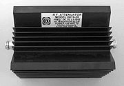
RF attenuators
Radio frequency attenuators are typically coaxial in structure with precision connectors as ports and coaxial, microstrip or thin-film internal structure. Above SHFSuper high frequency
Super high frequency refers to radio frequencies in the range of 3 GHz and 30 GHz. This band of frequencies is also known as the centimetre band or centimetre wave as the wavelengths range from ten to one centimetres....
special waveguide structure is required.
Important characteristics are:
- accuracy,
- low SWR,
- flat frequency-response and
- repeatability.
The size and shape of the attenuator depends on its ability to dissipate power. RF attenuators are used as loads for and as known attenuations and protective dissipations of power in measuring RF signals.
Audio attenuators
A line-level attenuator in the preamp or a power attenuator after the power amplifier uses electrical resistanceElectrical resistance
The electrical resistance of an electrical element is the opposition to the passage of an electric current through that element; the inverse quantity is electrical conductance, the ease at which an electric current passes. Electrical resistance shares some conceptual parallels with the mechanical...
to reduce the amplitude of the signal that reaches the speaker, reducing the volume of the output. A line-level attenuator has lower power handling, such as a 1/2-watt potentiometer
Potentiometer
A potentiometer , informally, a pot, is a three-terminal resistor with a sliding contact that forms an adjustable voltage divider. If only two terminals are used , it acts as a variable resistor or rheostat. Potentiometers are commonly used to control electrical devices such as volume controls on...
or voltage divider and controls preamp level signals, whereas a power attenuator has higher power handling capability, such as 10 watts or more, and is used between the power amplifier and the speaker.
- Power attenuator (guitar)Power attenuator (guitar)In conjunction with an electric guitar amplifier, a power attenuator is used to divert and dissipate some or all of the amplifier's excess or unneeded power in order to reduce the volume of sound produced by the speaker.- Explanation :...
- Guitar amplifierGuitar amplifierA guitar amplifier is an electronic amplifier designed to make the signal of an electric or acoustic guitar louder so that it will produce sound through a loudspeaker...
Component values for resistive pads and attenuators
This section concerns pi-pads, T-pads and L-pads made entirely from resistors and terminated on each port with a purely real resistance.- All impedances, currents, voltages and two-port parameters will be assumed to be purely real. For practical applications, this assumption is often close enough.
- The pad is designed for a particular load impedance, ZLoad, and a particular source impedance, Zs.
- The impedance seen looking into the input port will be ZS if the output port is terminated by ZLoad.
- The impedance seen looking into the output port will be ZLoad if the input port is terminated by ZS.
Reference figures for attenuator component calculation
The attenuator two-port is generally bidirectional. However in this section it will be treated as though it were one way. In general, either of the two figures above applies, but the figure on the left (which depicts the source on the left) will be tacitly assumed most of the time. In the case of the L-pad, the right figure will be used if the load impedance is greater than the source impedance.Each resistor in each type of pad discussed is given a unique designation to decrease confusion.
The L-pad component value calculation assumes that the design impedance for port 1 (on the left) is equal or higher than the design impedance for port 2.
Terms used
- Pad will include pi-pad, T-pad, L-pad, attenuator, and two-port.
- Two-port will include pi-pad, T-pad, L-pad, attenuator, and two-port.
- Input port will mean the input port of the two-port.
- Output port will mean the output port of the two-port.
- Symmetric means a case where the source and load have equal impedance.
- Loss means the ratio of power entering the input port of the pad divided by the power absorbed by the load.
- Insertion Loss means the ratio of power that would be delivered to the load if the load were directly connected to the source divided by the power absorbed by the load when connected through the pad.
Symbols used
Passive, resistive pads and attenuators are bidirectional two-ports, but in this section they will be treated as unidirectional.- ZS = the output impedance of the source.
- ZLoad = the input impedance of the load.
- Zin = the impedance seen looking into the input port when ZLoad is connected to the output port. Zin is a function of the load impedance.
- Zout = the impedance seen looking into the output port when Zs is connected to the input port. Zout is a function of the source impedance.
- Vs = source open circuit or unloaded voltage.
- Vin = voltage applied to the input port by the source.
- Vout = voltage applied to the load by the output port.
- Iin = current entering the input port from the source.
- Iout = current entering the load from the output port.
- Pin = Vin Iin = power entering the input port from the source.
- Pout = Vout Iout = power absorbed by the load from the output port.
- Pdirect = the power that would be absorbed by the load if the load were connected directly to the source.
- Lpad = 10 log10 (Pin / Pout ) always. And if Zs = ZLoad then Lpad = 20 log10 (Vin / Vout ) also. Note, as defined, Loss ≥ 0 dB
- Linsertion = 10 log10 (Pdirect / Pout ). And if Zs = ZLoad then Linsertion = Lpad.
- Loss ≡ Lpad. Loss is defined to be Lpad.
Symmetric T pad resistor calculation
 see Valkenburg p 11-3
Symmetric pi pad resistor calculation
 see Valkenburg p 11-3
L-Pad for impedance matching resistor calculation
If a source and load are both resistive (i.e. Z1 and Z2 have zero or very small imaginary part) then a resistive L-pad can be used to match them to each other. As shown, either side of the L-pad can be the source or load, but the Z1 side must be the side with the higher impedance. see Valkenburg p 11-3
Large positive numbers means loss is large. The loss is a monotonic function
Monotonic function
In mathematics, a monotonic function is a function that preserves the given order. This concept first arose in calculus, and was later generalized to the more abstract setting of order theory....
of the impedance ratio. Higher ratios require higher loss.
Converting T-pad to pi-pad

Converting pi-pad to T-pad

T-pad to impedance parameters
- The impedance parameters for a passive two-port are

- It is always possible to represent a resistive t-pad as a two-port. The representation is particularly simple using impedance parameters as follows:

Impedance parameters to T-pad
- The preceding equations are trivially invertible, but if the loss is not enough, some of the t-pad components will have negative resistances.

Impedance parameters to pi-pad
- These preceding T-pad parameters can be algebraically converted to pi-pad parameters.
-

Pi-pad to admittance parameters
- The admittance parameters for a passive two port are
- It is always possible to represent a resistive pi pad as a two-port. The representation is particularly simple using admittance parameters as follows:
Admittance parameters to pi-pad
- The preceding equations are trivially invertible, but if the loss is not enough, some of the pi-pad components will have negative resistances.
General case, determining impedance parameters from requirements
Because the pad is entirely made from resistors, it must have a certain minimum loss to match source and load if they are not equal.
The minimum loss is given by

Although a passive matching two-port can have less loss, if it does it will not be convertible to a resistive attenuator pad.

Once these parameters have been determined, they can be implemented as a T or pi pad as discussed above.
External links


