
AS-Interface
Encyclopedia
AS-Interface is an industrial networking solution (physical layer, data access method and protocol) used in PLC, DCS and PC-based automation systems. It is designed for connecting simple field I/O devices (e.g. binary ON/OFF devices such as actuators, sensors, rotary encoders, analog inputs and outputs, push buttons, and valve position sensors) in discrete manufacturing and process applications using a single 2-conductor cable.
AS-Interface is an 'open' technology supported by a multitude of automation equipment vendors. According to AS-Interface International there are currently, over 18 Million AS-i field devices are installed globally, growing at about 2 million per year.
AS-Interface is a networking alternative to the hard wiring of field devices. It can be used as a partner network for higher level fieldbus networks such as *Profibus
, *DeviceNet
, Interbus and *Industrial Ethernet
, for whom it offers a low-cost remote I/O solution. It is used in automation applications, including conveyor control, packaging machines, process control valves, bottling plants, electrical distribution systems, airport carousels, elevators, bottling lines and food production lines.
AS-Interface provides a basis for Functional Safety in machinery safety/emergency stop applications. Safety devices communicating over AS-Interface follow all the normal data rules. The required level of data verification is provided by dynamic changes in the data. This technology is called Safety as Work and allows safety devices and standard, non-safe devices to be connected to the same network. Using appropriate safe input hardware (e.g. light curtains, e-stop buttons, and door interlock switches), AS-Interface can provide safety support up to SIL (Safety Integrity Level) 3 according to EN 62061, CAT 4 according to EN954-1 as well as Performance Level e (PL e) according to EN ISO 13849-1.
The AS-Interface specification is managed by AS-International, a member funded organization located in Gelenhausen/Germany. Several international daughter organizations exist around the world.
The underlying communication procedure is a Master-Slave method, by which the master initiates data exchange with a slave and requires the slave to respond within its defined maximum time, making AS-Interface a deterministic networking solution. Conformance testing by an independent certification lab assures that certified products from all manufacturers will communicate on a given network.
AS-Interface data exchanges are based on a Master-Call, where the data frame consists of a 5-bit device addresses and 4-bit data packets (e.g. digital output information). The total length of the Master-Call 14 bit. The resulting Slave-Response is 7 bit long, containing 4 bit of user information (e.g. the values of slaves inputs).
Voltage levels on the network range between and data protection, in addition to the framing bits, is accomplished via Manchester-II
coding, a highly symmetrical, floating layout with Alternating Pulse Modulation. The networks bit time is . Segment length is limited to 100 meters.. Under certain conditions so-called a Terminator and/or Tuner can be used to extend the allowable segment length to 200m or 300m, respectively.
s, photoelectric sensor
s, capacitive sensors and ultrasonic sensor
s. Once development was completed the consortium was resolved and a member organization, AS-International, was founded. The first operational system was shown at the 1994 Hannover fair (Hannover Messe).
and Gateways
) was not increased. Instead, one of the four output bits was used to select between the so-called A and B nodes. This enabled each of the 31 addresses to be used twice. The address space was increased to 1A to 31A plus 1B to 31B. As a consequence of using an output bit as the A/B selector, the fourth output bit was not available to the user and binary I/O nodes built to this profile offered a maximum of 4 inputs and 3 outputs, increasing the total amount of I/O on a single network to 248 inputs and 186 outputs. The maximum update time of a fully loaded network is
With these new capabilities, AS-Interface becomes the ideal partner network for any of the currently available Ethernet based industrial protocols. Gateways to EtherNet/IPTM, PROFINET, Modbus/TCP, SERCOS III
and others are available. Some controls experts have voiced the opinion that within the next 10 years networking solutions positioned between AS-Interface and Ethernet will not be used in any new installation. In a worst case scenario, using 62 nodes with 4 inputs and 4 outputs each the update time is for the inputs and for the outputs.
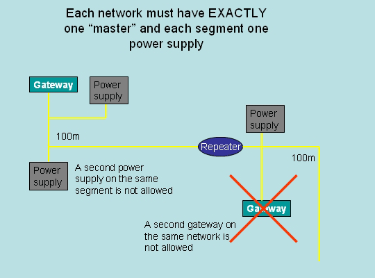
communication method, any network must have only one master at a time.
. These supplies have certain unique characteristics regarding internal circuitry and output voltage. Standard 24VDC power supplies can not be used to directly power a segment. The total length AS-Interface network cable in a single segment must be no more than 100m. If the total network length must be longer repeaters can be used. As the repeater galvanically isolates any two segment a new power supply must be used on the far side of the repeater.
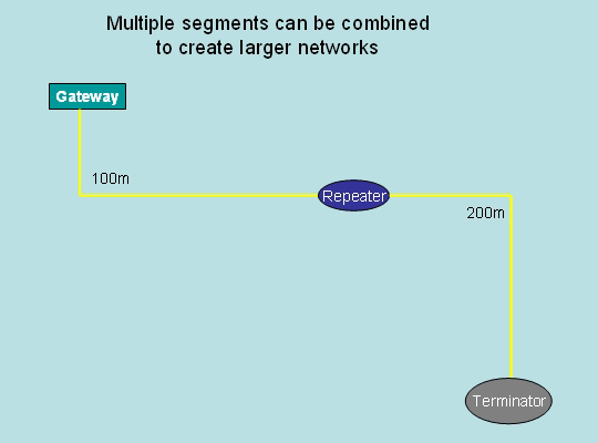
A common misconception exists concerning the number of repeaters in a network. It has been stated that the maximum length of an AS-Interface network can be 300m, created by using two repeaters. This is not the case at all! What matters is not how many repeaters are using but rather how many repeaters any data packet, originating at a Scanner or Gateway, has to cross before reaching the I/O node. Due to the tight timing constraints defined each packet can at most travel across two repeaters before reaching an AS-Interface node. This has the following consequences:
The current specification Version 3.0 has adds many the ability to construct many new types of I/O combinations, including binary modules with 4 inputs and 4 outputs supporting A/B addressing.
 There are several types of cables available. Yellow cable is usually used to power AS-Interface modules and enable communication between the field devices and the scanner or Gateway. This cable is offered in several jacket materials to address specific applications needs. The AS-Interface black cable is typically used to supply modules with 24VDC AUX power. No communication takes place on this cable. Similar to the yellow cable, the black cable is also produced using various jacket material to address the specific needs of the application. A red jacketed cable has been defined but is virtually unused. Its intended use was in applications where AC power is supplied to the field nodes. The two leads inside the AS-Interface cable are brown (+ lead) and blue (- lead) independent of material makeup and outer jacket color.
Using these basic rules it should be clear that
In some applications longer networks are desirable (e.g. Process Automation applications). This is possible through the installation of Terminator and Tuners.
are used.
AS-Interface is an 'open' technology supported by a multitude of automation equipment vendors. According to AS-Interface International there are currently, over 18 Million AS-i field devices are installed globally, growing at about 2 million per year.
AS-Interface is a networking alternative to the hard wiring of field devices. It can be used as a partner network for higher level fieldbus networks such as *Profibus
Profibus
PROFIBUS is a standard for field bus communication in automation technology and was first promoted in 1989 by BMBF...
, *DeviceNet
DeviceNet
DeviceNet is a network system used in the automation industry to interconnect control devices for data exchange. It uses Controller Area Network as the backbone technology and defines an application layer to cover a range of device profiles...
, Interbus and *Industrial Ethernet
Industrial Ethernet
Industrial Ethernet refers to the use of the Ethernet family of computer network technologies in an industrial environment, for automation and process control. A number of techniques are used to adapt Ethernet for the needs of industrial processes, which require real time behavior...
, for whom it offers a low-cost remote I/O solution. It is used in automation applications, including conveyor control, packaging machines, process control valves, bottling plants, electrical distribution systems, airport carousels, elevators, bottling lines and food production lines.
AS-Interface provides a basis for Functional Safety in machinery safety/emergency stop applications. Safety devices communicating over AS-Interface follow all the normal data rules. The required level of data verification is provided by dynamic changes in the data. This technology is called Safety as Work and allows safety devices and standard, non-safe devices to be connected to the same network. Using appropriate safe input hardware (e.g. light curtains, e-stop buttons, and door interlock switches), AS-Interface can provide safety support up to SIL (Safety Integrity Level) 3 according to EN 62061, CAT 4 according to EN954-1 as well as Performance Level e (PL e) according to EN ISO 13849-1.
The AS-Interface specification is managed by AS-International, a member funded organization located in Gelenhausen/Germany. Several international daughter organizations exist around the world.
Overview
AS-Interface is a system that requires four basic components:- Exactly one network master, in most cases in the form of a Gateway to a higher level industrial network or a PLC backplane card,
- A number of network slaves, in most cases input and output modules,
- Exactly one power supply used to power the network slaves and enabling communication with the network master, and
- The wiring infrastructure, in most case accomplished using the yellow flat cable.
The underlying communication procedure is a Master-Slave method, by which the master initiates data exchange with a slave and requires the slave to respond within its defined maximum time, making AS-Interface a deterministic networking solution. Conformance testing by an independent certification lab assures that certified products from all manufacturers will communicate on a given network.
AS-Interface data exchanges are based on a Master-Call, where the data frame consists of a 5-bit device addresses and 4-bit data packets (e.g. digital output information). The total length of the Master-Call 14 bit. The resulting Slave-Response is 7 bit long, containing 4 bit of user information (e.g. the values of slaves inputs).
Voltage levels on the network range between and data protection, in addition to the framing bits, is accomplished via Manchester-II
Manchester code
In telecommunication and data storage, Manchester code is a line code in which the encoding of each data bit has at least one transition and occupies the same time...
coding, a highly symmetrical, floating layout with Alternating Pulse Modulation. The networks bit time is . Segment length is limited to 100 meters.. Under certain conditions so-called a Terminator and/or Tuner can be used to extend the allowable segment length to 200m or 300m, respectively.
History
AS-Interface was developed during the late 1980 and early 1990 by a group (consortium) of 11 companies mostly known for their offering of industrial non-contact sensing devices like inductive sensorInductive sensor
An inductive sensor is an electronic proximity sensor, which detects metallic objects without touching them.The sensor consists of an induction loop. Electric current generates a magnetic field, which collapses generating a current that falls asymptotically toward zero from its initial level when...
s, photoelectric sensor
Photoelectric sensor
A photoelectric sensor, or photoeye, is a device used to detect the distance, absence, or presence of an object by using a light transmitter, often infrared, and a photoelectric receiver. They are used extensively in industrial manufacturing. There are three different functional types: opposed ,...
s, capacitive sensors and ultrasonic sensor
Ultrasonic sensor
Ultrasonic sensors work on a principle similar to radar or sonar which evaluate attributes of a target by interpreting the echoes from radio or sound waves respectively. Ultrasonic sensors generate high frequency sound waves and evaluate the echo which is received back by the sensor...
s. Once development was completed the consortium was resolved and a member organization, AS-International, was founded. The first operational system was shown at the 1994 Hannover fair (Hannover Messe).
Original Specification (1994, Version 2.04)
In its original form the network was capable of supporting up to 31 binary I/O devices, where each device could exchange 4 bit of input and 4 bit of output data, resulting in a total of 124 inputs and 124 outputs on a single network. Important features like Automatic Single Node Replacement were already part of the system. The network update time is easily calculated by multiplying the number I/O nodes with the deterministic update time for each node (approximately 150 microseconds), for a maximum update time of This simplified calculation does not include the Management Phase which is negligible for typical installations.Enhancements (1998, Version 2.11)
Following its introduction users quickly adopted AS-Interface, driving the demand for additional functionality and features. As a consequence, these demands were addressed with certain specification enhancements allowing the creation of analog input/output devices and increasing the number of possible binary I/O devices to 62. Diagnostics functionality was also enhanced by the creation of the Peripheral Fault Bit. In order to retain full forward and backward compatibility, the size of the data frame exchanged between the network master (ScannersScanners
Scanners is a 1981 science-fiction horror film written and directed by David Cronenberg and starring Jennifer O'Neill, Stephen Lack, Michael Ironside, and Patrick McGoohan...
and Gateways
Gateway (computer program)
A gateway is a link between two computer programs or systems such as Internet Forums. A gateway acts as a portal between two programs allowing them to share information by communicating between protocols on a computer or between dissimilar computers....
) was not increased. Instead, one of the four output bits was used to select between the so-called A and B nodes. This enabled each of the 31 addresses to be used twice. The address space was increased to 1A to 31A plus 1B to 31B. As a consequence of using an output bit as the A/B selector, the fourth output bit was not available to the user and binary I/O nodes built to this profile offered a maximum of 4 inputs and 3 outputs, increasing the total amount of I/O on a single network to 248 inputs and 186 outputs. The maximum update time of a fully loaded network is
Additional capabilities (2005/2007, Version 3.0)
By 2005 it became necessary to address additional user requirements. Also, the increased usage of Ethernet based industrial protocols called for a low level solution that overcame the inherent shortcomings of Ethernet (e.g. restricted topology, large data frame, costly usage of switches ...) This specification addressed the users requirements by defining new communication profiles for binary and analog data plus the introduction of a serial data transmission profile. The following is an incomplete list of the new capabilities- Binary I/O nodes supporting A/B addressing with 4 Inputs and 4 Outputs
- Binary I/O nodes supporting A/B addressing with 8 Inputs and 8 Outputs
- Configurable (8, 12 or 16 bit) fast analog channel
- Full Duplex bit serial data channel
With these new capabilities, AS-Interface becomes the ideal partner network for any of the currently available Ethernet based industrial protocols. Gateways to EtherNet/IPTM, PROFINET, Modbus/TCP, SERCOS III
SERCOS III
sercos III is the third generation of the sercos interface, a globally standardized open digital interface for the communication between industrial controls, motion devices, and input/output devices . sercos III merges the hard real-time aspects of the sercos interface with Ethernet. It is based...
and others are available. Some controls experts have voiced the opinion that within the next 10 years networking solutions positioned between AS-Interface and Ethernet will not be used in any new installation. In a worst case scenario, using 62 nodes with 4 inputs and 4 outputs each the update time is for the inputs and for the outputs.
Components
An AS-Interface network requires only a few basic components falling into the following general categories:- Scanners and Gateways (also called masters)
- Power supplies and repeaters
- Modules (also called slaves)
- Network cable, installation hardware and useful tool (infrastructure)
Scanners and Gateways
The Scanner/Gateway performs two functions. With respect to the AS-Interface network it is a master, performing the data exchange with the modules and updating its internal I/O image. The functionality of the master is defined in the Master Profile of the AS-Interface specification. As part of specification version 3.0 the M4 Master Profile has been defined. Any given network can only have one Scanner/Gateway. With respect to a connected PLC/DCS or PC the Scanner/Gateway is a slave. The AS-Interface community typically uses the word Gateway when the AS-Interface master connects to an upper-level network like DeviceNet, Profibus or any of the industrial Ethernet flavors. On the other hand, if it resides on the backplane of a PLC it is usually referred to as a Scanner. Since AS-Interface communication is based on the Master-SlaveMaster-slave
Master-slave may refer to:* Master-slave dialectic, philosophical concept* Master-slave * Master-Slave manipulator, see remote manipulator...
communication method, any network must have only one master at a time.
Power supply
Any AS-Interface segment must be powered. This is typically accomplished connecting an AS-Interface power supplyPower supply
A power supply is a device that supplies electrical energy to one or more electric loads. The term is most commonly applied to devices that convert one form of electrical energy to another, though it may also refer to devices that convert another form of energy to electrical energy...
. These supplies have certain unique characteristics regarding internal circuitry and output voltage. Standard 24VDC power supplies can not be used to directly power a segment. The total length AS-Interface network cable in a single segment must be no more than 100m. If the total network length must be longer repeaters can be used. As the repeater galvanically isolates any two segment a new power supply must be used on the far side of the repeater.
A common misconception exists concerning the number of repeaters in a network. It has been stated that the maximum length of an AS-Interface network can be 300m, created by using two repeaters. This is not the case at all! What matters is not how many repeaters are using but rather how many repeaters any data packet, originating at a Scanner or Gateway, has to cross before reaching the I/O node. Due to the tight timing constraints defined each packet can at most travel across two repeaters before reaching an AS-Interface node. This has the following consequences:
- Linear networks with the Scanner/Gateway mounted at one end can be 300m long
- Linear network with 600m length can be constructed when the Scanner/Gateway is mounted in the middle segment
- Star shaped networks with virtually no length limitation are possible
Modules
This is by far the largest group of components and includes binary and analog I/O modules, stack lights, pushbuttons, sensors with integrated ASIC, valve control boxes, E-stops, light curtains; in general any device that can exchange data with the PLC. Each module on the network must have a unique address. For AS-Interface the address space ranges from 0 to 31, where 0 cannot be used, but is reserved for Automatic Single Node Replacement. Since adoption of specification 2.11 this address space is further divided into A and B extended addresses. As a result, using a module designed to support this addressing mode, it possible to have two modules at each address; one at the A half and one at the B half. (Ex. 1A and 1B, 17A and 17B)The current specification Version 3.0 has adds many the ability to construct many new types of I/O combinations, including binary modules with 4 inputs and 4 outputs supporting A/B addressing.
Network cable
The vast majority of AS-Interface installations utilize the AS-Interface flat cable, defined as part of the AS-Interface specifications. A relatively small number of industries (e.g. valve control in process automation) use a round cable, mostly because it is easier to pull through conduit. While the shape of the cable does not matter (any other cable can be used) the electrical characteristics of the selected cable matters greatly. To prevent problems due to improper cable, most professional suggest the AS-Interface flat cable. This cable is designed to make use of a cable piercing technology. When an AS-Interface module is installed on the network, piercing needles penetrate the cable jacket and displace the internal copper strands without cutting them. This allows AS-Interface modules to be installed anywhere on the network without cutting and preparing (i.e. removing cable jacket, stripping insulation and possibly applying a ferule) the cable first. The result is a faster installation without the chance of inadvertent shorts between the leads.Designing a Network
An AS-Interface network is a collection of network segments. There are very few rule that need to be satisfied when designing an AS-Interface network:- There can be no duplicate addressed on a network
- Each segment must be 100m or less in total cable length
- Each network must power exactly one master
- Each segment must have power exactly one AS-Interface power supply
- When repeaters are used, a slave can not be more than "two repeater transitions" from the master
- The shape (i.e. topology) of a segment is arbitrary (unrestricted)
Using these basic rules it should be clear that
- A linear network, with the master at one end of the network, can be 300m long
- A linear network, with the master "in the middle" of the network, can be 500m long
In some applications longer networks are desirable (e.g. Process Automation applications). This is possible through the installation of Terminator and Tuners.
are used.