
X-ray image intensifier
Encyclopedia
An x-ray image intensifier (XRII), is an imaging component which converts x-rays into a visible image.
The term image intensifier
refers to a specific component of an x-ray imaging system, which allows low intensity x-rays to be converted to a visible light output. The device contains a low absorbency/scatter input window, typically aluminum, input fluorescent screen, photocathode, electron optics, output fluorescent screen and output window. These parts are all mounted in a high vacuum environment within glass or more recently, metal/ceramic. It allows the viewer to more easily see the structure of the object being imaged than past fluorescent screens. The X-ray II requires lower dose rates due to more efficient conversion of x-ray quanta to visible light. This device was originally introduced in 1948.
Viewing of the output was via mirrors and optical systems until the adaption of television systems in the 1960s. Additionally, the output was able to be captured on systems with a 100mm cut film camera using pulsed outputs from an x-ray tube similar to a normal radiographic exposure; the difference being the II rather than a film screen cassette provided the image for the film to record.
The input screens range from 15–57 cm, with the 23 cm, 33 cm and 40 cm being among the most common. Within each image intensifier, the actual field size can be changed using the voltages applied to the internal electron optics to achieve magnification and reduced viewing size. For example, the 23 cm commonly used in cardiac applications can be set to a format of 23, 17, and 13 cm. Because the output screen remains fixed in size, the output appears to "magnify" the input image.

One class commonly utilizes a radiolucent patient examination table with an under-table mounted tube and an imaging system mounted over the table, while the other is commonly referred to as a C-arm system used where greater flexibility in the examination process is needed such as neuro or cardiac imaging.
Modern imaging systems on both configurations are limited in capability only by the desired features the users will want. All frame rates, storage (local or PACS), image capture devices etc are now far lower in cost than before, software configurable and based on COTS components for all but the camera/II or flat panel devices.
The non-C-arm based systems are used in most X-ray departments as 'screening rooms'. The types of investigations for which this machine can be used for is vast, including:
The C-arm systems are commonly used for studies requiring the maximum positional flexibility such as:
A mobile image intensifier generally consists of two units, the x-ray generator and image system on a portable C-arm and the workstation unit used to store and manipulate the images. The C-arm unit consists of a C-arm with a variety of movements that allows for use in a variety of surgical procedures such as cardiology, orthopedics and urology. The C-arm provides the appropriate structure to mount an image intensifier and an X-ray tube with a beam limiting device positioned directly opposite from and aligned centrally to each other.
The c-arm is capable of many movements:
The x-ray generator, dose control system and collimator controls are usually housed in the chassis on which the C-arm is mounted. All of the control systems are closed loop systems which are directed by the master controller initial program settings. The master controller generally is found in the work station. User controls on the C-arm allow the operator to modify the operation of the system while in use. I.e. format size, slot collimator position, dose rate etc.
The c-arm must be compact and lightweight to allow easy positioning with adequate space to work around and a wide range of motion while yet remaining inflexible enough so as to avoid misalignment due to flexion caused by the mass of the X-ray tube or Image system assemblies.
Workstation unit
Much of the operation of the machine is from the workstation unit. This has the following features:
Types of X-ray tube
Two types of X-ray tube may be fitted, fixed anode or rotating anode.
Typical features of fixed anode tubes include:
1.8 by 1.8 mm focal spot size for radiographic applications.
Typical features of rotating anode tubes include:
The housing also has a heat storage limitation, typically 1200-1250kHU
Electronic capabilities
The images can be manipulated in many ways on the computer screen.
Examples of this are:
Generator and range of exposures
Modern systems use a digital high frequency generator with typically 20,000 cycles per second. The range of kVp settings may be from 40kV to 110kV. The tube current is typically 0.1mA to 6mA for fluoroscopy examinations. For radiographic mode the mA is fixed at about 20mA to 60mA. mAs values vary from 0.16 to 160 for radiographic application. The electronic timer varies from 0.1sec to 4.0sec for radiographic exposures.
Image intensifiers, size and features
They may be fitted with a range of different types of image intensifiers; typically 16 cm or 22 cm.
Typical specifications for a 16 cm intensifier are:
Typical specifications for a 22 cm intensifier are:
Flat detectors - image intensifier replacement
Flat Detectors are currently offered by Ziehm Imaging Siemens, GE, and Philips Medical. The Flat Detector (FD) will replace the Image Intensifier. The advantages of this technology include lower patient dose and increased image quality because the x-rays are always pulsed, and no deterioration of the image quality over time.
Type of TV camera and coupling to II
Older machines may have a vidicon type pickup tube, with direct fiber-optic coupling to the image intensifier. Modern machines may have a CCD camera.
Radiation safety features
Special features
3D imaging
Used for CT like imaging in the operating theatre environment.
See
Potential safety issues
Failure of the x-ray beam collimation may lead to primary beam x-ray exposure outside of the selected image intensifier input area. This would result in image degradation light generated outside the area of the image intensifier input at magnification will cause additional loss of contrast of the image with increased noise. Additionally, unnecessary additional dose to the patient would result. If the c-arm or fittings are damaged, the x-ray tube and intensifier may become misaligned resulting in image degradation or loss, as well as presenting a potential injury to staff and patient if the structural integrity of the C-arm or mounted components are compromised.
(DSA). All image intensifiers are set up with software capable of adjusting settings to suit different user requirements, depending on the procedure and body area being imaged. In simple flouroscopy for example, imaging of the throat would not require the same amount of exposure as that of the abdomen. And on DSA capable models, preset programs are available which enables the user to decide a rate of how many images or frames per second are acquired.
The term image intensifier
Image intensifier
An image intensifier tube is a vacuum tube device for increasing the intensity of available light in an optical system to allow use under low light conditions such as at night, to facilitate visual imaging of low-light processes such as fluorescence of materials to X-rays or gamma rays, or for...
refers to a specific component of an x-ray imaging system, which allows low intensity x-rays to be converted to a visible light output. The device contains a low absorbency/scatter input window, typically aluminum, input fluorescent screen, photocathode, electron optics, output fluorescent screen and output window. These parts are all mounted in a high vacuum environment within glass or more recently, metal/ceramic. It allows the viewer to more easily see the structure of the object being imaged than past fluorescent screens. The X-ray II requires lower dose rates due to more efficient conversion of x-ray quanta to visible light. This device was originally introduced in 1948.
Viewing of the output was via mirrors and optical systems until the adaption of television systems in the 1960s. Additionally, the output was able to be captured on systems with a 100mm cut film camera using pulsed outputs from an x-ray tube similar to a normal radiographic exposure; the difference being the II rather than a film screen cassette provided the image for the film to record.
The input screens range from 15–57 cm, with the 23 cm, 33 cm and 40 cm being among the most common. Within each image intensifier, the actual field size can be changed using the voltages applied to the internal electron optics to achieve magnification and reduced viewing size. For example, the 23 cm commonly used in cardiac applications can be set to a format of 23, 17, and 13 cm. Because the output screen remains fixed in size, the output appears to "magnify" the input image.
Clinical applications
Modern imaging systems will use the image intensifier as the source of images supplied to a storage system.- As an fixed piece of equipment in a dedicated screening room
- Mobile equipment for use in an operating theatreOperating theatreAn operating theater was a non-sterile, tiered theater or amphitheater in which students and other spectators could watch surgeons perform surgery...
Components
- C-arm (encompasses the actual X-ray source and image intensifier)
- Table
- Fluoroscopic exposure and program controls
- Post processing software
- Viewing monitors
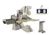
Permanent/Fixed Fluoroscopic Systems
There are two main configurations of permanently installed fluoroscopic systems.One class commonly utilizes a radiolucent patient examination table with an under-table mounted tube and an imaging system mounted over the table, while the other is commonly referred to as a C-arm system used where greater flexibility in the examination process is needed such as neuro or cardiac imaging.
Modern imaging systems on both configurations are limited in capability only by the desired features the users will want. All frame rates, storage (local or PACS), image capture devices etc are now far lower in cost than before, software configurable and based on COTS components for all but the camera/II or flat panel devices.
The non-C-arm based systems are used in most X-ray departments as 'screening rooms'. The types of investigations for which this machine can be used for is vast, including:
- Barium studies (swallows, meals, enemas)
- Endoscopy studies (ERCP) (Some sites will opt for a portable C-arm system for this)
- Fertility studies (HSGHysterosalpingographyHysterosalpingography is a radiologic procedure to investigate the shape of the uterine cavity and the shape and patency of the fallopian tubes. It entails the injection of a radio-opaque material into the cervical canal and usually fluoroscopy with image intensification...
)
The C-arm systems are commonly used for studies requiring the maximum positional flexibility such as:
- Angiography studies (peripheral, central and cerebral)
- Therapeutic studies (Line placements i.e. Permacath/Hickman, transjugular biopsies, TIPS stent, embolisations)
- Cardiac studies (PTCAPTCAPTCA may refer to:* Percutaneous transluminal coronary angioplasty, a type of angioplasty* Percutaneous transhepatic cholangiography...
) - Orthopedic procedures (ORIF, DHS, MUA, spinal work) - again generally using a portable C-arm maximum flexibility in positional use. There are very few permanently installed C-arms in an O.R. setting.The workflow seldom justifies this sort of dedication of one O.R. or Permanent C-arm
Mobile Fluoroscopic System AKA "portable C-arm"
General configuration and range of movementsA mobile image intensifier generally consists of two units, the x-ray generator and image system on a portable C-arm and the workstation unit used to store and manipulate the images. The C-arm unit consists of a C-arm with a variety of movements that allows for use in a variety of surgical procedures such as cardiology, orthopedics and urology. The C-arm provides the appropriate structure to mount an image intensifier and an X-ray tube with a beam limiting device positioned directly opposite from and aligned centrally to each other.
The c-arm is capable of many movements:
- Horizontal travel: about 200 mm
- Orbital travel: about 115 degrees
- Motorized vertical travel: 460 mm
- Wig-wag about +/-12 cm (entire C-Arm and Image Intensifier)
- C-arm rotation about the horizontal axis +/- 210 degrees
The x-ray generator, dose control system and collimator controls are usually housed in the chassis on which the C-arm is mounted. All of the control systems are closed loop systems which are directed by the master controller initial program settings. The master controller generally is found in the work station. User controls on the C-arm allow the operator to modify the operation of the system while in use. I.e. format size, slot collimator position, dose rate etc.
The c-arm must be compact and lightweight to allow easy positioning with adequate space to work around and a wide range of motion while yet remaining inflexible enough so as to avoid misalignment due to flexion caused by the mass of the X-ray tube or Image system assemblies.
Workstation unit
Much of the operation of the machine is from the workstation unit. This has the following features:
- Various handles for movement and positioning
- Power switch and exposure switch
- Cable hanger
- Brake pedal
- Controls for radiographic and fluoroscopic settings
- Various interconnect cables
- Hard disk and optical disk writer/rewriter
- DVD R/RW
- PACSPicture archiving and communication systemA picture archiving and communication system is a medical imaging technology which provides economical storage of, and convenient access to, images from multiple modalities . Electronic images and reports are transmitted digitally via PACS; this eliminates the need to manually file, retrieve, or...
system connection allowing access to patient information, annotation, - Advanced image quality enhancement software such as noise reduction, zoom control
- Ability to save and swap images between monitors
- Contrast and brightness controls
- May have one or dual 17 inch or larger monitors
- Advanced image processing such as noise reduction
Types of X-ray tube
Two types of X-ray tube may be fitted, fixed anode or rotating anode.
Typical features of fixed anode tubes include:
- Typical anode heat capacity load 30,000 - 50,000 heat units
- Single or dual focused anode, with 0.5 by 0.5 mm focal spot for fluroscopic applications and
1.8 by 1.8 mm focal spot size for radiographic applications.
- The angle on the anode target of about 12 degrees.
Typical features of rotating anode tubes include:
- 0.3 mm focal spot for better image detail
- Typical anode heat rating of 300 000 heat units for longer exposure times
- Allows for a longer tube life
The housing also has a heat storage limitation, typically 1200-1250kHU
Electronic capabilities
The images can be manipulated in many ways on the computer screen.
Examples of this are:
- Cine loop replay- Allows review of a dynamic scene without extra dose
- Cine Loop editing- Shorter loops can be made over review of a dynamic scene
- 16 Picture overview- For quick overview.
- Zoom- Fast magnification.
- Relative stenosis measurement- Can measure the distance of two vessels for vasuclar procedures.
- Test Annotation- To label all images
Generator and range of exposures
Modern systems use a digital high frequency generator with typically 20,000 cycles per second. The range of kVp settings may be from 40kV to 110kV. The tube current is typically 0.1mA to 6mA for fluoroscopy examinations. For radiographic mode the mA is fixed at about 20mA to 60mA. mAs values vary from 0.16 to 160 for radiographic application. The electronic timer varies from 0.1sec to 4.0sec for radiographic exposures.
Image intensifiers, size and features
They may be fitted with a range of different types of image intensifiers; typically 16 cm or 22 cm.
Typical specifications for a 16 cm intensifier are:
- Maximum resolution is 44 lp/cm at the centre of the screen.
- Anti-scatter grid of 8:1, focused at 90 cm.
- Removable cassette holder that is mounted on the image intensifier and holds a 24X30 film.
- Rotation 360 degrees
Typical specifications for a 22 cm intensifier are:
- Resolution is 44 lp/cm at the centre of the screen.
- Magnification mode - allows a maximum resolution of 51 lp/cm at the centre of the screen
- Stationary anti-scatter grid 10:1, focused at 90 cm.
- Removable cassette holder that is mounted on the image intensifier and holds a 24X30 film.
- Rotation 360 degrees
Flat detectors - image intensifier replacement
Flat Detectors are currently offered by Ziehm Imaging Siemens, GE, and Philips Medical. The Flat Detector (FD) will replace the Image Intensifier. The advantages of this technology include lower patient dose and increased image quality because the x-rays are always pulsed, and no deterioration of the image quality over time.
Type of TV camera and coupling to II
Older machines may have a vidicon type pickup tube, with direct fiber-optic coupling to the image intensifier. Modern machines may have a CCD camera.
Radiation safety features
- Last image hold, "freezing" the screen and availing for examining the screen without exposing the patient to unnecessary radiation.
- Pulsed fluroscopy
- Single pulse fluroscopy mode
- Manual mode in order to reduce dose (ALARA)
- Fluoroscopy timer warning
- Movements of II allow distance between patient and image detector low, so therefore reducing dose to patient.
- Beam limitation devices to minimize beam area
Special features
- Real time viewing
- Remote control keypad
- Removable cassette holder, for both fluroscopy and plain film images
- Contrast correction
- Zoom
- Edge enhancement
- Digital subtraction
- Wheels fitted with cable deflectors
3D imaging
Used for CT like imaging in the operating theatre environment.
- 3D Navigation
- Checking post surgical screw placement
See
- Ziehm Imaging
- Siemens Healthcare
Potential safety issues
Failure of the x-ray beam collimation may lead to primary beam x-ray exposure outside of the selected image intensifier input area. This would result in image degradation light generated outside the area of the image intensifier input at magnification will cause additional loss of contrast of the image with increased noise. Additionally, unnecessary additional dose to the patient would result. If the c-arm or fittings are damaged, the x-ray tube and intensifier may become misaligned resulting in image degradation or loss, as well as presenting a potential injury to staff and patient if the structural integrity of the C-arm or mounted components are compromised.
Technical capabilities
Image intensifiers are usually set up for two purposes. For either plain fluoroscopy or digital subtraction angiographyDigital subtraction angiography
Digital subtraction angiography is a type of fluoroscopy technique used in interventional radiology to clearly visualize blood vessels in a bony or dense soft tissue environment. Images are produced using contrast medium by subtracting a 'pre-contrast image' or the mask from later images, once...
(DSA). All image intensifiers are set up with software capable of adjusting settings to suit different user requirements, depending on the procedure and body area being imaged. In simple flouroscopy for example, imaging of the throat would not require the same amount of exposure as that of the abdomen. And on DSA capable models, preset programs are available which enables the user to decide a rate of how many images or frames per second are acquired.
Future developments
- Flat panel
- Dual head
- Low dose Imaging
- Flat detector currently offered by Ziehm Imaging and Philips Medical. The flat detector will replace the image intensifier. The advantages of this technology include lower patient dose and increased image quality because the X-rays are always pulsed.