
Raster scan
Encyclopedia
A raster scan, or raster scanning, is the rectangular pattern of image capture and reconstruction in television. By analogy, the term is used for raster graphics
, the pattern of image storage and transmission used in most computer bitmap
image systems. The word raster comes from the Latin word rastrum (a rake), which is derived from radere (to scrape); see also rastrum
, an instrument for drawing musical staff lines. The pattern left by the tines of a rake, when drawn straight, resembles the parallel lines of a raster: this line-by-line scanning is what creates a raster. It's a systematic process of covering the area progressively, one line at a time. Although often a great deal faster, it's similar in the most-general sense to how one's gaze travels when one reads lines of text.
as it is read from the video source, as in television systems, or can be further divided into discrete pixels for processing in a computer system. This ordering of pixels by rows is known as raster order, or raster scan order. Analog television has discrete scan lines (discrete vertical resolution), but does not have discrete pixels (horizontal resolution) – it instead varies the signal continuously over the scan line. Thus, while the number of scan lines (vertical resolution) is unambiguously defined, the horizontal resolution is more approximate, according to how quickly the signal can change over the course of the scan line.
 In raster scanning, the beam sweeps horizontally left-to-right at a steady rate, then blanks and rapidly moves back to the left, where it turns back on and sweeps out the next line. During this time, the vertical position is also steadily increasing (downward), but much more slowly — there is one vertical sweep per image frame, but one horizontal sweep per line of resolution. Thus each scan line is sloped slightly "downhill" (towards the lower right), with a slope of approximately –1/horizontal resolution, while the sweep back to the left (retrace) is significantly faster than the forward scan, and essentially horizontal. The resulting tilt in the scan lines is very small, and is dwarfed in effect by screen convexity and other modest geometrical imperfections.
There is a misconception that once a scan line is complete, a CRT display in effect suddenly jumps internally, by analogy with a typewriter or printer's paper advance or line feed, before creating the next scan line. As discussed above, this does not exactly happen: the vertical sweep continues at a steady rate over a scan line, creating a small tilt. Steady-rate sweep is done, instead of a stairstep of advancing every row, because steps are hard to implement technically, while steady-rate is much easier. The resulting tilt is compensated in most CRTs by the tilt and parallelogram adjustments, which impose a small vertical deflection as the beam sweeps across the screen. When properly adjusted, this deflection exactly cancels the downward slope of the scanlines. The horizontal retrace, in turn, slants smoothly downward as the tilt deflection is removed; there's no jump at either end of the retrace. In detail, scanning of CRTs is done by magnetic deflection, by changing the current in the coils of the deflection yoke. Rapidly changing the deflection (a jump) requires a voltage spike to be applied to the yoke, and the deflection can only react as fast as the inductance and spike magnitude permit. Electronically, the inductance of the deflection yoke's vertical windings is relatively high, and thus the current in the yoke, and therefore the vertical part of the magnetic deflection field, can change only slowly.
In fact, spikes do occur, both horizontally and vertically, and the corresponding horizontal blanking interval and vertical blanking interval
give the deflection currents settle time to retrace and settle to their new value. This happens during the blanking interval.
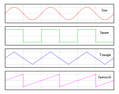
In electronics, these (usually steady-rate) movements of the beam[s] are called "sweeps", and the circuits that create the currents for the deflection yoke (or voltages for the horizontal deflection plates in an oscilloscope) are called the sweep circuits. These create a sawtooth wave
: steady movement across the screen, then a typically rapid move back to the other side, and likewise for the vertical sweep.
Furthermore, wide-deflection-angle CRTs need horizontal sweeps with current that changes proportionally faster toward the center, because the center of the screen is closer to the deflection yoke than the edges. A linear change in current would swing the beams at a constant rate angularly; this would cause horizontal compression toward the center.
The porches and associated blanking are to provide fall time
and settle time for the beam to move back to the left (the voltage to decrease), and for ringing
to die down. The vertical frame (VFrame) consists of exactly the same components, but only occurs once per image frame, and the times are considerably longer. The details of these intervals are called the video timing. See Video timing details revealed for a diagram of these. These are mostly not visible to end users, but were visible in the case of XFree86 Modeline
s, where users of XFree86
could (and sometimes needed to) manually adjust these timings, particularly to achieve certain resolutions or refresh rate
s.
To clear up possible confusion: Referring to the magnetic deflection fields, if there were none, all beams would hit the screen near the center. The farther away from the center, the greater the strength of the field needed. Fields of one polarity move the beam up and left, and those of the opposite polarity move it down and right. At some point near the center, the magnetic deflection field is zero. So, therefore, a scan begins as the field decreases. Midway, it passes through zero, and smoothly increases again to complete the scan.
After one line has been created on the screen and the beams are blanked, the magnetic field reaches its designed maximum. Relative to the time required for a forward scan, it then changes back relatively quickly to what's required to position the beam beyond the left edge of the visible (unblanked) area. This process occurs with all beams blanked, and is called the retrace. At the left edge, the field steadily decreases in magnitude to start another forward scan, and soon after the start, the beams unblank to start a new visible scan line.
A similar process occurs for the vertical scan, but at the display refresh rate (typically 50 to 75 Hz). A complete field starts with a polarity that would place the beams beyond the top of the visible area, with the vertical component of the deflection field at maximum,. After some tens of horizontal scans (but with the beams blanked), the vertical component of the unblank, combined with the horizontal unblank, permits the beams to show the first scan line. Once the last scan line is written, the vertical component of the magnetic field continues to increase by the equivalent of a few percent of the total height before the vertical retrace takes place. Vertical retrace is comparatively slow, occurring over a span of time required for several tens of horizontal scans. (In old analog TVs, typically, setting brightness to maximum made the vertical retrace visible.)
In analog TV, originally it was too costly* to create a simple sequential raster scan of the type just described with a fast-enough refresh rate and sufficient horizontal resolution, although the French 819-line system had better definition than other standards of its time. To obtain a flicker-free display, analog TV used a variant of the scheme in moving-picture film projectors, in which each frame of the film is shown twice or three times. To do that, the shutter closes and opens again to increase the flicker rate, but not the data update rate. *Practical video (similar to digital dot clock) bandwidth, including transmission bandwidth
Modern high-definition TV displays use data formats like progressive scan in computer monitors (such as "1080p", 1080 lines, progressive), or interlaced (such as "1080i").
Raster scans have been used in (naval gun) fire-control radar, although they were typically narrow rectangles. They were used in pairs (for bearing, and for elevation). In each display, one axis was angular offset from the line of sight, and the other, range. Radar returns brightened the video. Search and weather radars have a circular display (Plan Position Indicator, PPI) that covers a round screen, but this is not technically a raster.
Analog PPIs have sweeps that move outward from the center, and the angle of the sweep matches antenna rotation, up being north, or the bow of the ship.
was formed by a tool known as a rastrum
as early as 1833. The concept of raster scanning was inherent in the original mechanical disc-scanning
television patent of Paul Nipkow in 1884. The term raster was used for a halftone printing screen pattern as early as 1894. Similar terminology was used in German at least from 1897; Eder writes of "die Herstellung von Rasternegativen fur Zwecke der Autotypie" (the production of raster negatives for halftones).Max Dieckmann and Gustav Glage were the first to produce actual raster images on a cathode-ray tube (CRT); they patented their techniques in Germany in 1906. It has not been determined whether they used the word raster in their patent or other writings.
An early use of the term raster with respect to image scanning via a rotating drum is Arthur Korn's 1907 book which says (in German): "...als Rasterbild auf Metall in solcher Weise aufgetragen, dass die hellen Töne metallisch rein sind, oder umgekehrt" (...as a raster image laid out on metal in such way that the bright tones are metallically pure, and vice versa). Korn was applying the terminology and techniques of halftone
printing, where a "Rasterbild" was a halftone-screened printing plate.There were more scanning-relevant uses of Raster by German authors Eichhorn in 1926: "die Tönung der Bildelemente bei diesen Rasterbildern" and "Die Bildpunkte des Rasterbildes" ("the tone of the picture elements of this raster image" and "the picture points of the raster image"); and Schröter in 1932: "Rasterelementen," "Rasterzahl," and "Zellenraster" ("raster elements," "raster count," and "cell raster").
The first use of raster specifically for a television scanning pattern is often credited to Baron Manfred von Ardenne who wrote in 1933: "In einem Vortrag im Januar 1930 konnte durch Vorführungen nachgewiesen werden, daß die Braunsche Röhre hinsichtlich Punktschärfe und Punkthelligkeit zur Herstellung eines präzisen, lichtstarken Rasters laboratoriumsmäßig durchgebildet war" (In a lecture in January 1930 it was proven by demonstrations that the Braun tube was prototyped in the laboratory with point sharpness and point brightness for the production of a precise, bright raster). Raster was adopted into English television literature at least by 1936, in the title of an article in Electrician. The mathematical theory of image scanning was developed in detail using Fourier transform
techniques in a classic paper by Mertz and Gray of Bell Labs in 1934.
Raster graphics
In computer graphics, a raster graphics image, or bitmap, is a data structure representing a generally rectangular grid of pixels, or points of color, viewable via a monitor, paper, or other display medium...
, the pattern of image storage and transmission used in most computer bitmap
Bitmap
In computer graphics, a bitmap or pixmap is a type of memory organization or image file format used to store digital images. The term bitmap comes from the computer programming terminology, meaning just a map of bits, a spatially mapped array of bits. Now, along with pixmap, it commonly refers to...
image systems. The word raster comes from the Latin word rastrum (a rake), which is derived from radere (to scrape); see also rastrum
Rastrum
A rastrum is a five-pointed writing implement used in music manuscripts to draw parallel staff lines. The word "raster" is derived from the Latin for "rake". Rastra were used to draw lines on paper that had not been pre-ruled, and were widely used in Europe until printed staff paper became cheap...
, an instrument for drawing musical staff lines. The pattern left by the tines of a rake, when drawn straight, resembles the parallel lines of a raster: this line-by-line scanning is what creates a raster. It's a systematic process of covering the area progressively, one line at a time. Although often a great deal faster, it's similar in the most-general sense to how one's gaze travels when one reads lines of text.
Scan lines
In a raster scan, an image is subdivided into a sequence of (usually horizontal) strips known as "scan lines". Each scan line can be transmitted in the form of an analog signalAnalog signal
An analog or analogue signal is any continuous signal for which the time varying feature of the signal is a representation of some other time varying quantity, i.e., analogous to another time varying signal. It differs from a digital signal in terms of small fluctuations in the signal which are...
as it is read from the video source, as in television systems, or can be further divided into discrete pixels for processing in a computer system. This ordering of pixels by rows is known as raster order, or raster scan order. Analog television has discrete scan lines (discrete vertical resolution), but does not have discrete pixels (horizontal resolution) – it instead varies the signal continuously over the scan line. Thus, while the number of scan lines (vertical resolution) is unambiguously defined, the horizontal resolution is more approximate, according to how quickly the signal can change over the course of the scan line.
Scanning pattern
There is a misconception that once a scan line is complete, a CRT display in effect suddenly jumps internally, by analogy with a typewriter or printer's paper advance or line feed, before creating the next scan line. As discussed above, this does not exactly happen: the vertical sweep continues at a steady rate over a scan line, creating a small tilt. Steady-rate sweep is done, instead of a stairstep of advancing every row, because steps are hard to implement technically, while steady-rate is much easier. The resulting tilt is compensated in most CRTs by the tilt and parallelogram adjustments, which impose a small vertical deflection as the beam sweeps across the screen. When properly adjusted, this deflection exactly cancels the downward slope of the scanlines. The horizontal retrace, in turn, slants smoothly downward as the tilt deflection is removed; there's no jump at either end of the retrace. In detail, scanning of CRTs is done by magnetic deflection, by changing the current in the coils of the deflection yoke. Rapidly changing the deflection (a jump) requires a voltage spike to be applied to the yoke, and the deflection can only react as fast as the inductance and spike magnitude permit. Electronically, the inductance of the deflection yoke's vertical windings is relatively high, and thus the current in the yoke, and therefore the vertical part of the magnetic deflection field, can change only slowly.
In fact, spikes do occur, both horizontally and vertically, and the corresponding horizontal blanking interval and vertical blanking interval
Vertical blanking interval
The vertical blanking interval , also known as the vertical interval or VBLANK, is the time difference between the last line of one frame or field of a raster display, and the beginning of the first line of the next frame. It is present in analog television, VGA, DVI and other signals. During the...
give the deflection currents settle time to retrace and settle to their new value. This happens during the blanking interval.
In electronics, these (usually steady-rate) movements of the beam[s] are called "sweeps", and the circuits that create the currents for the deflection yoke (or voltages for the horizontal deflection plates in an oscilloscope) are called the sweep circuits. These create a sawtooth wave
Sawtooth wave
The sawtooth wave is a kind of non-sinusoidal waveform. It is named a sawtooth based on its resemblance to the teeth on the blade of a saw....
: steady movement across the screen, then a typically rapid move back to the other side, and likewise for the vertical sweep.
Furthermore, wide-deflection-angle CRTs need horizontal sweeps with current that changes proportionally faster toward the center, because the center of the screen is closer to the deflection yoke than the edges. A linear change in current would swing the beams at a constant rate angularly; this would cause horizontal compression toward the center.
Printers
Computer printers create their images basically by raster scanning. Laser printers use a spinning polygonal mirror (or an optical equivalent) to scan across the photosensitive drum, and paper movement provides the other scan axis. Considering typical printer resolution, the "downhill" effect is minuscule. Inkjet printers have multiple nozzles in their printheads, so many (dozens to hundreds) of "scan lines" are written together, and paper advance prepares for the next batch of scan lines. However, converting vector-based data into the form required by a display, or printer, requires a Raster Image Processor (RIP).Fonts
Computer text is mostly created from font files that describe the outlines of each printable character or symbol (glyph). (A minority are "bit maps".) These outlines have to be converted into what are effectively little rasters, one per character, before being rendered (displayed or printed) as text, in effect merging their little rasters into that for the page.Video timing
In detail, each line (horizontal frame or HFrame) consists of:- scanline, when beam is unblanked, and moving steadily to the right
- front porchFront PorchFront Porch, Inc. provides services to Internet Service Providers. Front Porch technology enables an Internet Service Provider to insert its own messages to be presented to users as they use their web browsers, such as customer service notices or online advertising...
, when beam is blanked, and moving steadily to the right - sync pulse, when beam is blanked, and moves rapidly back to the left
- back porch, when beam is blanked, and again moving steadily to the right.
The porches and associated blanking are to provide fall time
Fall time
In electronics, fall time \scriptstyle t_f\, is the time required for the amplitude of a pulse to decrease from a specified value to another specified value...
and settle time for the beam to move back to the left (the voltage to decrease), and for ringing
Ringing (signal)
In electronics, signal processing, and video, ringing is unwanted oscillation of a signal, particularly in the step response...
to die down. The vertical frame (VFrame) consists of exactly the same components, but only occurs once per image frame, and the times are considerably longer. The details of these intervals are called the video timing. See Video timing details revealed for a diagram of these. These are mostly not visible to end users, but were visible in the case of XFree86 Modeline
XFree86 Modeline
A modeline is a configuration line in xorg.conf or the XFree86 configuration file that provides information to the X server about a connected computer monitor or television and how to drive it at a specified display resolution...
s, where users of XFree86
XFree86
XFree86 is an implementation of the X Window System. It was originally written for Unix-like operating systems on IBM PC compatibles and is now available for many other operating systems and platforms. It is free and open source software under the XFree86 License version 1.1. It is developed by the...
could (and sometimes needed to) manually adjust these timings, particularly to achieve certain resolutions or refresh rate
Refresh rate
The refresh rate is the number of times in a second that a display hardware draws the data...
s.
Theory and history
In a cathode-ray-tube (CRT) display, when the electron beams are unblanked, the horizontal deflection component of the magnetic field created by the deflection yoke makes the beams scan "forward" from left to right at a constant rate. The data for consecutive pixels goes (at the pixel clock rate) to the digital-to-analog converters for each of the three primary colors. (For modern flat-panel displays, however, the pixel data remains digital.) As the scan line is drawn, at the right edge of the display, all beams are blanked, but the magnetic field continues to increase in magnitude for a short while after blanking.To clear up possible confusion: Referring to the magnetic deflection fields, if there were none, all beams would hit the screen near the center. The farther away from the center, the greater the strength of the field needed. Fields of one polarity move the beam up and left, and those of the opposite polarity move it down and right. At some point near the center, the magnetic deflection field is zero. So, therefore, a scan begins as the field decreases. Midway, it passes through zero, and smoothly increases again to complete the scan.
After one line has been created on the screen and the beams are blanked, the magnetic field reaches its designed maximum. Relative to the time required for a forward scan, it then changes back relatively quickly to what's required to position the beam beyond the left edge of the visible (unblanked) area. This process occurs with all beams blanked, and is called the retrace. At the left edge, the field steadily decreases in magnitude to start another forward scan, and soon after the start, the beams unblank to start a new visible scan line.
A similar process occurs for the vertical scan, but at the display refresh rate (typically 50 to 75 Hz). A complete field starts with a polarity that would place the beams beyond the top of the visible area, with the vertical component of the deflection field at maximum,. After some tens of horizontal scans (but with the beams blanked), the vertical component of the unblank, combined with the horizontal unblank, permits the beams to show the first scan line. Once the last scan line is written, the vertical component of the magnetic field continues to increase by the equivalent of a few percent of the total height before the vertical retrace takes place. Vertical retrace is comparatively slow, occurring over a span of time required for several tens of horizontal scans. (In old analog TVs, typically, setting brightness to maximum made the vertical retrace visible.)
In analog TV, originally it was too costly* to create a simple sequential raster scan of the type just described with a fast-enough refresh rate and sufficient horizontal resolution, although the French 819-line system had better definition than other standards of its time. To obtain a flicker-free display, analog TV used a variant of the scheme in moving-picture film projectors, in which each frame of the film is shown twice or three times. To do that, the shutter closes and opens again to increase the flicker rate, but not the data update rate. *Practical video (similar to digital dot clock) bandwidth, including transmission bandwidth
Interlaced scanning
To obtain flicker-free pictures, analog CRT TVs write only odd-numbered scan lines on the first vertical scan; then, the even-numbered lines follow, placed ("interlaced") between the odd-numbered lines. This is called interlaced scanning. (In this case, positioning the even-numbered lines does require precise position control; in old analog TVs, trimming the Vertical Hold adjustment made scan lines space properly. If slightly misadjusted, the scan lines would appear in pairs, with spaces between.)Modern high-definition TV displays use data formats like progressive scan in computer monitors (such as "1080p", 1080 lines, progressive), or interlaced (such as "1080i").
Raster scans have been used in (naval gun) fire-control radar, although they were typically narrow rectangles. They were used in pairs (for bearing, and for elevation). In each display, one axis was angular offset from the line of sight, and the other, range. Radar returns brightened the video. Search and weather radars have a circular display (Plan Position Indicator, PPI) that covers a round screen, but this is not technically a raster.
Analog PPIs have sweeps that move outward from the center, and the angle of the sweep matches antenna rotation, up being north, or the bow of the ship.
History
A set of lines forming a musical staffStaff (music)
In standard Western musical notation, the staff, or stave, is a set of five horizontal lines and four spaces that each represent a different musical pitch—or, in the case of a percussion staff, different percussion instruments. Appropriate music symbols, depending upon the intended effect,...
was formed by a tool known as a rastrum
Rastrum
A rastrum is a five-pointed writing implement used in music manuscripts to draw parallel staff lines. The word "raster" is derived from the Latin for "rake". Rastra were used to draw lines on paper that had not been pre-ruled, and were widely used in Europe until printed staff paper became cheap...
as early as 1833. The concept of raster scanning was inherent in the original mechanical disc-scanning
Nipkow disk
A Nipkow disk , also known as scanning disk, is a mechanical, geometrically operating image scanning device, invented by Paul Gottlieb Nipkow...
television patent of Paul Nipkow in 1884. The term raster was used for a halftone printing screen pattern as early as 1894. Similar terminology was used in German at least from 1897; Eder writes of "die Herstellung von Rasternegativen fur Zwecke der Autotypie" (the production of raster negatives for halftones).Max Dieckmann and Gustav Glage were the first to produce actual raster images on a cathode-ray tube (CRT); they patented their techniques in Germany in 1906. It has not been determined whether they used the word raster in their patent or other writings.
An early use of the term raster with respect to image scanning via a rotating drum is Arthur Korn's 1907 book which says (in German): "...als Rasterbild auf Metall in solcher Weise aufgetragen, dass die hellen Töne metallisch rein sind, oder umgekehrt" (...as a raster image laid out on metal in such way that the bright tones are metallically pure, and vice versa). Korn was applying the terminology and techniques of halftone
Halftone
Halftone is the reprographic technique that simulates continuous tone imagery through the use of dots, varying either in size, in shape or in spacing...
printing, where a "Rasterbild" was a halftone-screened printing plate.There were more scanning-relevant uses of Raster by German authors Eichhorn in 1926: "die Tönung der Bildelemente bei diesen Rasterbildern" and "Die Bildpunkte des Rasterbildes" ("the tone of the picture elements of this raster image" and "the picture points of the raster image"); and Schröter in 1932: "Rasterelementen," "Rasterzahl," and "Zellenraster" ("raster elements," "raster count," and "cell raster").
The first use of raster specifically for a television scanning pattern is often credited to Baron Manfred von Ardenne who wrote in 1933: "In einem Vortrag im Januar 1930 konnte durch Vorführungen nachgewiesen werden, daß die Braunsche Röhre hinsichtlich Punktschärfe und Punkthelligkeit zur Herstellung eines präzisen, lichtstarken Rasters laboratoriumsmäßig durchgebildet war" (In a lecture in January 1930 it was proven by demonstrations that the Braun tube was prototyped in the laboratory with point sharpness and point brightness for the production of a precise, bright raster). Raster was adopted into English television literature at least by 1936, in the title of an article in Electrician. The mathematical theory of image scanning was developed in detail using Fourier transform
Fourier transform
In mathematics, Fourier analysis is a subject area which grew from the study of Fourier series. The subject began with the study of the way general functions may be represented by sums of simpler trigonometric functions...
techniques in a classic paper by Mertz and Gray of Bell Labs in 1934.
See also
- Raster graphicsRaster graphicsIn computer graphics, a raster graphics image, or bitmap, is a data structure representing a generally rectangular grid of pixels, or points of color, viewable via a monitor, paper, or other display medium...
- RasterisationRasterisationRasterisation is the task of taking an image described in a vector graphics format and converting it into a raster image for output on a video display or printer, or for storage in a bitmap file format....
- Image resolutionImage resolutionImage resolution is an umbrella term that describes the detail an image holds. The term applies to raster digital images, film images, and other types of images. Higher resolution means more image detail....
- Counter-scanningCounter-scanningCounter-scanning is a scanning method that allows correcting raster distortions caused by drift of the probe of scanning microscope relative to the measured surface. During counter-scanning two surface scans, viz., direct scan and counter scan are obtained . The counter scan starts in the point...
- Computer display standardComputer display standardComputer display standards are often a combination of aspect ratio, display resolution, color depth, and refresh rate.This article describes the different display standards for computer displays.-History:...
- Broadcast television systemBroadcast television systemBroadcast television systems are encoding or formatting standards for the transmission and reception of terrestrial television signals. There are three main analog television systems in current use around the world: NTSC, PAL, and SECAM...
- Cathode-Ray Tube