

Plugboard
Encyclopedia
Jack (connector)
In electronics and electrical assemblies, the term jack commonly refers to a surface-mounted connector, often, but not always, with the female electrical contact or socket, and is the "more fixed" connector of a connector pair...
, or hubs, into which patch cords can be inserted to complete an electrical circuit. Control panels were used to direct the operation of some unit record equipment
Unit record equipment
Before the advent of electronic computers, data processing was performed using electromechanical devices called unit record equipment, electric accounting machines or tabulating machines. Unit record machines were as ubiquitous in industry and government in the first half of the twentieth century...
. Plugboards were used on some cipher machines, and some early computers.
Unit record equipment
Herman Hollerith
Herman Hollerith was an American statistician who developed a mechanical tabulator based on punched cards to rapidly tabulate statistics from millions of pieces of data. He was the founder of one of the companies that later merged and became IBM.-Personal life:Hollerith was born in Buffalo, New...
tabulator
Tabulating machine
The tabulating machine was an electrical device designed to assist in summarizing information and, later, accounting. Invented by Herman Hollerith, the machine was developed to help process data for the 1890 U.S. Census...
, earlier machines had been hard wired for specific applications. Removable control panels were introduced with the Hollerith (IBM) type 3-S tabulator in the 1920s. Different programs could be stored on separate plugboards, and then inserted into the tabulators as needed. IBM manuals use the word "program" only for calculators, such as the IBM 602
IBM 602
The IBM 602 Calculating Punch , introduced in 1946, was an electromechanical calculator capable of addition, subtraction, multiplication, and division. It was programmed using a plugboard control panel and was IBM's first machine that did division....
and IBM 604
IBM 604
The IBM 604 was a control panel programmable Electronic Calculating Punch introduced in 1948, and was a machine on which considerable expectations for the future of IBM were pinned and in which a corresponding amount of planning talent was invested...
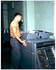
, that executed a sequence of operations. For all other machines, from sorters, interpreters, to the IBM 407
IBM 407
The IBM 407 Accounting Machine, introduced in 1949, was one of a long line of IBM tabulating machines dating back to the days of Herman Hollerith. It was the central component of any unit record equipment shop. In the late 1950s, the 407 was adapted as an input/output device on early computers,...
, the control panel "directed" or "automatic operation was obtained by..."
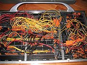
An IBM control panel was roughly one to two feet (300 to 600 mm) on a side and had a rectangular array of hubs. Plugs
Jack (connector)
In electronics and electrical assemblies, the term jack commonly refers to a surface-mounted connector, often, but not always, with the female electrical contact or socket, and is the "more fixed" connector of a connector pair...
at each end of a patch cord were inserted into hubs, making a connection between two contacts on the machine when the control panel was placed in the machine, thereby connecting an emitting hub to an accepting or entry hub. For example, in a card duplicator application a card column reading (emitting) hub might be connected to a punch magnet entry hub. It was a relatively simple matter to copy some fields, perhaps to different columns, and ignore other columns by suitable wiring. Tabulator control panels required dozens of patch cords for complex applications. Wiring a control panel required knowledge of the machine's functions and its timing constraints.
Many applications using unit record tabulators were later migrated to computers such as the IBM 1401
IBM 1401
The IBM 1401 was a variable wordlength decimal computer that was announced by IBM on October 5, 1959. The first member of the highly successful IBM 1400 series, it was aimed at replacing electromechanical unit record equipment for processing data stored on punched cards...
. Two programming languages, FARGO and RPG
RPG programming language
RPG is a high-level programming language for business applications.It has a long history, having been developed by IBM in 1959 as the Report Program Generator - a tool to replicate card processing on the IBM 1401 then updated to RPG II for the IBM System/3 in the late 1960s, and since evolved into...
, were created to aid this migration. Since tabulator control panels were based on the machine cycle, both FARGO and RPG emulated the notion of the machine cycle and training material showed the control panel vs. programming language coding sheet relationships.
Wiring of unit record equipment
The components of most unit record machines were synchronized to a rotating shaft. One rotation represented a single machine cycle, during which punched cardPunched card
A punched card, punch card, IBM card, or Hollerith card is a piece of stiff paper that contains digital information represented by the presence or absence of holes in predefined positions...
s would advance from one station to the next, a line might be printed, a total might be printed and so on. The cycles were divided into points according to when the rows on a punched card would appear under a read or punch station. On most machines, cards were fed face down, 9-edge first. Thus the first point in a card cycle would 9-time, the second 8 time and so on to 0-time. The times from 9 to 0 were known as digit times. Zero-time would be followed by 11 time and 12 time, also known as zone times.
The action caused by an electrical impulse on a wire depended on when it the cycle it occurred. Thus a pulse that occurred during 7-time on a wire connected to the column 26 punch magnet would punch a hole in row 7 of column 26. A pulse on the same wire that occurred at 4-time would punch a 4 in column 26. Impulses timed in this way often came from read brushes that detected holes punched in cards as they passed under the brushes, but such pulses were also emitted by other circuits, such as counter outputs. Zone impulses and digit impulses were combined for alphanumeric printing.
The control panel for each machine type presented exit (output) and entry (input) hubs in logical groupings. In many places, two or more adjacent hubs would be connected to allow more than one wire to be connected to that exit or entry. A few groups of hubs were wired together but not connected to any internal circuits. These could be used to connect multiple wires when needed. Small connector blocks called wire splits were also available to join three or four wires together, above the control panel. Several are visible in the photo of an IBM 402 panel.
The capabilities and sophistication of unit record machine components evolved over the first half of the 20th century and were often specific to the needs of a particular machine type. The following functional groupings were typical of later IBM machines:
- Read brushes, 80 exit hubs, one for each card column. A tabulating machine might have two or three read stations, each with its own set of 80 hubs. A reproducing punch might have an additional read station after the punch station for verification.
- Punch magnets Machines that could punch cards, such as a reproducing punch, had hub entries for each card column. An impulse to one of those entries triggered the electromagnet that initiated the punching of a hole at that column position.
- Print entries, one hub for each print position. Impulses to these entries controlled the motion of print bars or wheels to place the correct type element under the print hammers. The 407 also had exits from each print wheel that could then feed the counters for addition or subtraction. This insured that totals always matched what was printed.
- Counter entries. An IBM tabulating machine, such as the 402 or 407 series would have several counters available in different sizes. (For example, the IBM 402/403 had four sets each of 2, 4, 6 and 8 digit counters, labeled 2A, 2B, 2C, 2D, 4A, 4B etc.) Each counter had two counter control entries to specify either addition (plus) or subtraction (minus). If neither were pulsed, no operation was performed. If addition was commanded, a digit impulse wired from a column to a counter entry hub started the counter wheel turning. It stoped automatically at zero time. Thus a pulse at 8 time caused the wheel to advance 8 steps, adding the value 8 to that counter position. Carries within a group were performed automatically. Carry in and carry out hubs allowed counters to be combined, permitting longer numbers to be accumulated. Subtraction was more complicated and used nines complement arithmetic.
- Counter total exits. A counter's Total entry hub caused that counter to emit total pulses which could be wired to print positions. After a total was printed, the counter was reset. Special circuits allowed negative values to be printed correctly, not as nines complements, and a special exit was provided to allow an appropriate symbol ("cr" or "-") to be printed next to the number when it was negative.
- Comparing. Simple comparing circuits had two entries and one exit that emitted a pulse whenever pulses arrived at the entries at different times. Some machines, e.g. collators, could detect which number was higher if they were not equal. A tabulating machine might compare the account number on successive cards and print a total when a new account number appeared. For the compare function, IBM implemented what would now be called an XOR gateXOR gateThe XOR gate is a digital logic gate that implements an exclusive or; that is, a true output results if one, and only one, of the inputs to the gate is true . If both inputs are false or both are true , a false output results. Its behavior is summarized in the truth table shown on the right...
using opposing electromagnets. If neither magnet was energized or both magnets were energized at the same time, the relay armature would not move. If only one magnet was energized, the armature would move and touch one of two contacts placed on either side. The two contacts were wired together internally and connected to an exit hub that indicated an unequal comparison.
- Emitters were sets of 12 exit hubs that automatically generated a pulse at each specified time in the card cycle. The twelve exit hubs were wired to contacts on a rotary switch that turned with the card cycle. Thus wiring the 6 exit from an emitter to a punch magnet entry would cause a 6 to be punched at that position. Emitters might be used to put a numeric constant value, say a date, on every card. Alphanumeric constant data could be created by carefully combining digit and zone pulses. Later machines, such as the 407 also had a complete set of alphanumeric emitters that only required one wire to use.
- Selectors directed a pulse from a common entry to either of two outputs, depending on whether a relayRelayA relay is an electrically operated switch. Many relays use an electromagnet to operate a switching mechanism mechanically, but other operating principles are also used. Relays are used where it is necessary to control a circuit by a low-power signal , or where several circuits must be controlled...
magnet was energized. Many types of selectors were employed that differed in how the "pickup" relay was energized. In the simplest case, immediate (I) entries, the magnet was energized when a pulse was received and held for the remainder of the cycle. More complex selectors, called pilot selectors, had a D entry hub that caused the selector magnet to pick up on the next machine cycle, and X entry hub that also delayed but was only triggered by an 11 or 12 pulse. The one-cycle delay was needed because in most cases, by the time a pulse was detected it was too late to reliably take action in that cycle. Co-selectors had only an immediate input, but five sets of contacts and were typically triggered by a pilot selector's coupling exit, hence the names.
- Digit selectors were similar to emitters, with one exit hub for each cycle point, but they also had an entry hub that was switched to the successive exit hubs as the cycle progressed. A digit selector could be converted to a digit emitter by wiring its entry hub to a constant source of cycle pulses. But it could also be fed other signals and used to detect a particular digit. Wiring a first read brush to a digit selector's entry and connecting, say, its 4 exit to a pilot selector's D entry would cause that selector to transfer on the next read cycle if a 4 was punched in that first read brush's column.
- Column splits were relays that energized during only at 11 and 12-time, allowing digit pulses to be separated from zone pulses.
- Storage. Later machines such as the 407 and 602 could store several values for later use, by means of a mechanical device somewhat similar to an emitter, except it contained a sliding contact that determined at what time point an impulse was to be emitted. The contact slider was positioned electro-mechancially when a value was stored, and stayed in position until the storage was cleared.
Cypher machines
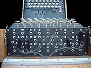
Enigma machine
An Enigma machine is any of a family of related electro-mechanical rotor cipher machines used for the encryption and decryption of secret messages. Enigma was invented by German engineer Arthur Scherbius at the end of World War I...
; it was not removable. In this case the plugboard acted as a "fourth rotor" in the rotor machine
Rotor machine
In cryptography, a rotor machine is an electro-mechanical device used for encrypting and decrypting secret messages. Rotor machines were the cryptographic state-of-the-art for a prominent period of history; they were in widespread use in the 1920s–1970s...
's workings. Plugboard wirings were part of the "day settings" that specified which rotors to insert into which slot, and which plugboard connections to make. In practice the plugboard did not improve the security of the cypher being generated, as it did not change with every keypress, unlike the rotors.
Early computers
The first version of the ENIACENIAC
ENIAC was the first general-purpose electronic computer. It was a Turing-complete digital computer capable of being reprogrammed to solve a full range of computing problems....
computer was programmed via cabling, switches and plugboards. ENIAC's cabling was later reconfigured to use the existing Function Tables data ROM memory as program ROM memory (the switches and plugboards continued to be used in the reconfigured ENIAC).
Plugboards remained in use in specialty-purpose computers for some time, acting as a ROM but able to be manually reprogrammed in the field. One example is the Ferranti Argus
Ferranti Argus
Ferranti's Argus computers were a line of industrial control computers offered from the 1960s into the 1980s. They were widely used in a variety of roles in Europe, particularly in the UK where they continue to serve as monitoring and control systems for nuclear reactors.-Original series:The...
computer, used on the Bristol Bloodhound missile, which feature a plugboard programmed by inserting small ferrite rods into slots, in effect creating a read-only core memory by hand.
Wiring the plugboard "programmed" the system, which operated as a sort of read only memory.
See also
- Enigma machine
- Powers-SamasPowers-SamasPowers-Samas was a British company which sold unit record equipment. The company was in competition with the British Tabulating Machine Company , with which it eventually merged in 1959 to form International Computers and Tabulators...
a British manufacturer of unit record equipment that used a removable "connection-box" with mechanical linkages instead of a plug board. - Telephone switchboardTelephone switchboardA switchboard was a device used to connect a group of telephones manually to one another or to an outside connection, within and between telephone exchanges or private branch exchanges . The user was typically known as an operator...