

PAROLI
Encyclopedia
Communications protocol
A communications protocol is a system of digital message formats and rules for exchanging those messages in or between computing systems and in telecommunications...
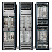
used inside a multi-shelf Carrier Routing System
Carrier Routing System
Carrier Routing System is a large-scale core router, developed by Cisco Systems, Inc. It runs IOS XR which is a train of IOS built upon the QNX microkernel. A single chassis holds a maximum of 16 line cards, and can run an OC-768 SONET interface...
from Cisco
Cisco Systems
Cisco Systems, Inc. is an American multinational corporation headquartered in San Jose, California, United States, that designs and sells consumer electronics, networking, voice, and communications technology and services. Cisco has more than 70,000 employees and annual revenue of US$...
and stands for parallel optical link
Paroli usage
It is used to connect the line-cards in a so called line-card chassis with the switching fabric in a switch-fabric chassis. As the traffic between these kind of chassis is comparable with the data that flows over a backplaneBackplane
A backplane is a group of connectors connected in parallel with each other, so that each pin of each connector is linked to the same relative pin of all the other connectors forming a computer bus. It is used as a backbone to connect several printed circuit boards together to make up a complete...
in a single-shelf system the required bandwidth is very high and as is the need for reliability the shelves are interconnected using several fibre optic cables.
As this protocol/feature is only used in multi-shelf Cisco-CRS systems you will only find it in IOS XR
IOS XR
IOS XR is a train of Cisco Systems' widely deployed Internetworking Operating System , used on their high-end carrier-grade routers such as the CRS-1, 12000, and ASR9000 series.-Architecture:...
the special high performance version of Cisco IOS
Cisco IOS
Cisco IOS is the software used on the vast majority of Cisco Systems routers and current Cisco network switches...
.
There are basically two types of multi-shelf CRS systems:
- single switch-fabric chassis and two line-card chassis
- two switch-fabric chassis and two line-card chassis
- four switch-fabric chassis and two line-card chassis
The second option allows for the most fault-tolerant system in a CRS system: although a single shelf switch-fabric allows for redundancy on most levels (power. fans, management-cards, switch-cards etc.), a multi-shelf system based on two switch-fabric cards and (at least) two line-card chassis will continue to run even when one of the switch-fabric shelfs is completely down. The four SCC/2 LCC also gives optimal availability and reliability without the loss of any throughput in case that a switch fabric module fails.
Distance between shelves
Although the different shelves of a multi-shelf routing system will often be placed directly next to each other the PAROLI system allows for some distance between the shelves. If you want to place the different shelves in different rooms (e.g. in a system with two switch-fabris chassis have one of these chassis with 50% of the line-card chassis in dataroom 1 and the rest of the system in room 2 so that even when there is fire in one room the system will continue to work) it is possible as long as the length of the fibre-optic canles doesn't exceed 100 meters (328 feet). This will also allow you to move individual shelves of the systemInterconnecting shelves
All traffic coming in into a multi-shelf CRS system will come in via an interface of a line card on a line-card shelf. The traffic is then sent to the switch-fabric shelf where the packet is processed and based on the desitination (and of course system-configuration) the data is then sent to the outgoing interface on a line-card in a line-card shelf. The inter shelf communication links will therefore process the same kind of data-volumes as a backplane will normally carry in any single-shelf router.To allow these kind of speeds via external fibre optic cabling Cisco designed special modules to make this possible. For a multi-shelf system you need three kind of connections between the line-card chassis and the switch-fabric chassis:
- 1:Management cabling
- 2:Controller cabling
- 3:Fabric cabling
Management Cabling
The management, alarm and external clock cabling is to allow management of the different shelves in the system. There are different type of management and clock signalling options. At least one management cabling is required and in general that will be the RP ethernet connection.- Console cabling: initial configuration of the route processor (RP) of a shelf a multi-shelf system is done via the console port. The ethernet management port will only become operational after configuring it with a terminal connected to a console port. Initial configuration of a shelf is done via the console port of a RP. The console port of the 22 (switch fabric shelf) or 2 port (line card shelf) SCGE card (see below) cannot be used to configure a new system. If you want all console ports of each RP connected you can use a terminal server
- AUX port: provides remote out of band access to the RP, similar to the console port, but is meant for remote access via a modem
- Management ethernet port:This will be the main means of configuring and managing the system after initial configuration. In general the ethernet ports of each RP in the system will be connected to an out-of-band ethernet LAN so you keep control over the system even when the CSR wouldn't be able to route any data. If the CSR is installed at the same location as the configuration system you will probably use a dedicated ethernet LAN. If the CSR is in a different location you will probably connect this (configuration) management (V)LAN withh your NOC via a network connection that doesn't use the CRS to route the data (or you have a fall-back method such as ISDN access to the local management LAN)
- Alarm-Out cabling: You can use the external alarm-out cicuits to raise alarms with the power modules
- External network clocking: If you use an external clock to synchronize your network components you can 'feed' this clock into all shelves.
Controller Cabling
For the controller cabling Cisco have created a special module for use in the fabric card chassis: the 22 port Shelf Controller Gigabit Ethernet module the SC-GE-22. And on the LCC's you use the two ethernet interfaces provided with the two RP's in each chassis.In a single SFC with two LCC you will install both SC-GE-22 modules in the single SFC and each interface of the RP connect twice to the single SFC. In a 2 x 2 setup one GE port of each RP connects to one SFC and the other GE port connects to the other SFC. In a four SFC setup the first RP connects to SFC 1 and 3 while the other RP of that shelf connects to SFC 2 and 4.
To allow for redundancy you will connect each ethernetport0 interface of each RP to a port on the first FC-FE-22 and each interface 1 to the second SC-FE-22. And to allow for communication between the two Sc-FE-22 modules (creating a mesh-network) you connect port 22 of each SC-FE-22 to each other. In a dual SFC each SC-FE-22 has a direct (full mesh) link to all 3 other SC-FE-22 and in a 4 SFC system you also create a full-mesh network between all FC-FE-22 modules.
This cabling means that for a one SFC and two LCC you will need 8+1 ethernet cables for network control, in a dual SFC you will need 14 cables (8xSC-LC + 6 LCC mesh) and in a 4 SFC-2 LCC you need 8 LC cables and 28 SFC-SFC mesh cables.
Fabric cabling
And finally you need the fabric cabling that will carry the actual data or payload between the line card chassis and the switch fabric chassis. For the interconnection the system uses 8 fabric planes, numbered 0 to7. In combination with that it uses a 3 components or stages. When a packet arrives via an interface on a linecard in a LCC (the ingress FCC) it is on stage 1, then goes to the switch-fabric (stage 2) and then to the desitination line-card (stage 3).It is of course possible that the linecard of the ingress resides in the same shelf as the egress line card, but this same 3 stage model is being used.In the LCC's you use stage 1 and 3 cards: S13 cards. In a SFC you have stage 2 cards S2. In a single SFC setup all 8 S2 cards reside in the single SFC, in a multi SFC setupthe S2 cards are distributed over the SFC's. For the communication based on tow line-card chassis you will need 72 fibres (3(S1,2,3) x 8(#planes) x 3(2xLCC+1FCC). Even when you have more than one SFC you still use 72 cables: in a two SFC setup 50% of the fibres from LCC connect to SFC1 and 50% to SFC2 and similar to a 4 node system).
These cables can be ordered in lenhths of 10-100 meter and come in sets of 24. Thus to interconnect a system you need 3 sets ordered in the length you require in steps of 5 meters
In the future configurations with more than two LCC's will be supported, but currently a multi-shelf configuration supports two lince card chassis and 1,2 or 3 switch facbric chassis.