Murray loop bridge
Encyclopedia

Bridge circuit
A bridge circuit is a type of electrical circuit in which two circuit branches are "bridged" by a third branch connected between the first two branches at some intermediate point along them. The bridge was originally developed for laboratory measurement purposes and one of the intermediate...
used for locating faults in underground or underwater cable
Cable
A cable is two or more wires running side by side and bonded, twisted or braided together to form a single assembly. In mechanics cables, otherwise known as wire ropes, are used for lifting, hauling and towing or conveying force through tension. In electrical engineering cables are used to carry...
s. It has been used for more than 100 years.
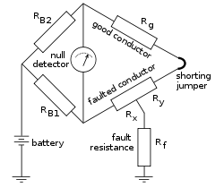
One end of the faulted cable is connected through a pair of resistor
Resistor
A linear resistor is a linear, passive two-terminal electrical component that implements electrical resistance as a circuit element.The current through a resistor is in direct proportion to the voltage across the resistor's terminals. Thus, the ratio of the voltage applied across a resistor's...
s to the voltage source. Also a null detector is connected. The other end of the cable is shorted. The bridge is brought to balance by changing the values of RB1 and RB2, which is achieved when:

which is equivalent to:

The value of resistance Rx is proportional the length Lx, thus the location of the fault can be calculated:

where L is the total length of the cable under test - a value proportional to Rg.
The method assumes a single fault exists, of low resistance compared with the undamaged cable insulation resistance, and that the cable conductors have uniform resistance per unit length.

