

Multiway switching
Encyclopedia
In building wiring, multiway switching is interconnection of two or more light switch
es to control lighting from more than one location. This allows lighting in a hallway or stairwell to be controlled from either end.
Three-way and four-way switches make it possible to control a light from multiple locations, such as the top and bottom of a stairway, or either end of a long hallway. These switches are externally similar to single-pole switches, but have extra connections which allow two circuits to be controlled. Toggling the switch disconnects one circuit and connects the other.
Electrically, a three-way switch is a single-pole, double-throw (SPDT) switch
. By connecting two of these switches together, toggling either switch changes the state of the light from off to on, or on to off. A four-way switch has two pairs of terminals which it connects either straight through, or crossed over. By connecting one or more four-way switches in-line with three-way switches at either end, the light can be controlled from three or more locations. Toggling any switch changes the state of the light from off to on, or on to off.
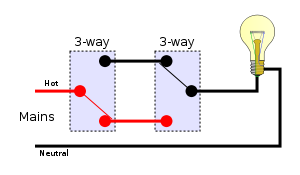
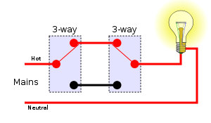
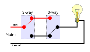
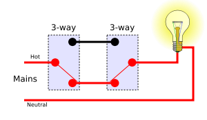
In the traveler system, the line hot is fed into the common terminal of one of the switches; the switches are then connected by a wire pair called "Travelers", as shown, and the lamp is connected to common of a second switch. This method requires two wires between the switches.
Using the traveler system, there are four possible combinations of switch positions: two with the light on and two with the light off.
violation as the neutral
is never switched. While this method requires three wires between the switches, it also gives the advantage of allowing loads at both ends of the switched circuit to be controlled from either end.
The alternative system is to join the three terminals of one switch to the corresponding terminals on the other switch. The incoming supply and the lamp are connected as shown. This method requires three wires between the switches.
The alternative system should not be confused with the Carter system. The alternative system is legal, but can be confusing.
. Two of the four switch position combinations are dangerous, and this wiring method has been prohibited by the National Electrical Code since 1923.
In the Carter system, the incoming live (energized)
and neutral wire
s are connected to the traveler screws of both 3-way switches, and the lamp is connected between the common screws of the two switches. If both switches are flipped to hot or both are flipped to neutral, there is no light; but if they are switched to opposite positions, there is light. The advantage of this method is that it uses just one wire to the light from each switch, having a hot and neutral in both switches.
The major problem with this method is that two switch combinations apply the live (hot) wire to the outer shell of the light socket, presenting a dangerous electrical shock hazard. The lampholder shell may still be energized even with the light off, which poses a risk when changing a bulb. This method is prohibited in building wiring where the neutral and live conductors must be distinguished.
As mentioned above, the above circuit can be extended by using multiple 4-way switches between the 3-way switches to extend switching ability to any number of locations.
s with low-voltage control circuits permit switching the power to lighting loads from an arbitrary number of locations. For each load a latching relay is used that maintains its on- or off-state, even if power to the building is interrupted. Mains power is wired through the relay to the load. Instead of running mains voltage to the switches, a safe, low voltage — typically 24 VAC — is connected to remote momentary toggle or rocker switches. The momentary switches are usually of form SPDT in (ON)-OFF-(ON) configuration. Pushing the switch actuator in one direction causes the relay contacts to close; pushing it in the opposite direction causes the relay contacts to open. Additional toggles can be wired in parallel as needed, and a master control can be added that turns all lights in the facility on or off simultaneously under the control of a timer or computer.
Residential use of such low voltage systems has become rare, and equipment for implementing them is not commonly carried by electrical suppliers, although it is still possible to find parts for maintaining existing installations. Multiway switching in residential applications is increasingly being implemented with power line signalling techniques, such as in the X10
system, available since the 1980s, and newer hybrid wired/wireless systems, such as Insteon
. See Home automation
.
Light switch
A light switch is a switch, most commonly used to operate electric lights, permanently connected equipment, or electrical outlets. In torches the switch is often near the bulb, but may be in the tail, or even the entire head itself may constitute the switch .-Wall-mounted switches:Switches for...
es to control lighting from more than one location. This allows lighting in a hallway or stairwell to be controlled from either end.
Three-way and four-way
This article follows American usage. Readers in the UK should read "two-way" for the American "three-way" and "intermediate" or "crossover" switch for the American "four-way".Three-way and four-way switches make it possible to control a light from multiple locations, such as the top and bottom of a stairway, or either end of a long hallway. These switches are externally similar to single-pole switches, but have extra connections which allow two circuits to be controlled. Toggling the switch disconnects one circuit and connects the other.
Electrically, a three-way switch is a single-pole, double-throw (SPDT) switch
Switch
In electronics, a switch is an electrical component that can break an electrical circuit, interrupting the current or diverting it from one conductor to another....
. By connecting two of these switches together, toggling either switch changes the state of the light from off to on, or on to off. A four-way switch has two pairs of terminals which it connects either straight through, or crossed over. By connecting one or more four-way switches in-line with three-way switches at either end, the light can be controlled from three or more locations. Toggling any switch changes the state of the light from off to on, or on to off.
Two locations
Switching a load on or off from two locations (for instance, turning a light on or off from either end of a flight of stairs) requires two SPDT switches. There are two basic methods or systems of wiring to achieve this.Traveler system
The traveler system may also be called the "Common system", due to the line and load of the system being connected to the common terminal of their respective three-way switch.In the traveler system, the line hot is fed into the common terminal of one of the switches; the switches are then connected by a wire pair called "Travelers", as shown, and the lamp is connected to common of a second switch. This method requires two wires between the switches.
Using the traveler system, there are four possible combinations of switch positions: two with the light on and two with the light off.
| Off | On |
|---|---|
 |
 |
 |
 |
Alternative system
The alternative system is also known as the California 3-way or the coast 3-way. It is a method of wiring using four conductors and two three-way switches. It allows for a hot receptacle at both ends of the circuit as well as switched light outlets on both ends. Its main benefit is that it saves on conductors when the wire to the light is located near the wire from the mains, since they are both in the same switch box. It can also light a lamp (or a second lamp) that is near the second switch box without having to pass an extra wire (with the standard system an extra wire would be needed). Its main drawback is that it is wired up to the 3-way switches in a non-standard manner that can cause confusion and mis-wiring for anyone who follows the initial installer. When wired correctly, it does not pose an electrical codeElectrical code
An electrical code is a set of regulations for electrical wiring. The intention of an electrical code is to provide standards to ensure electrical wiring systems that are safe and unlikely to produce either electric shock or fires. Electrical codes are usually devised by national or international...
violation as the neutral
Ground and neutral
Since the neutral point of an electrical supply system is often connected to earth ground, ground and neutral are closely related. Under certain conditions, a conductor used to connect to a system neutral is also used for grounding of equipment and structures...
is never switched. While this method requires three wires between the switches, it also gives the advantage of allowing loads at both ends of the switched circuit to be controlled from either end.
The alternative system is to join the three terminals of one switch to the corresponding terminals on the other switch. The incoming supply and the lamp are connected as shown. This method requires three wires between the switches.
The alternative system should not be confused with the Carter system. The alternative system is legal, but can be confusing.
Carter system
The Carter system was a method of wiring 3-way switches in the era of knob and tube wiringKnob and tube wiring
Knob and tube wiring was an early standardized method of electrical wiring in buildings, in common use in North America from about 1880 to the 1930s...
. Two of the four switch position combinations are dangerous, and this wiring method has been prohibited by the National Electrical Code since 1923.
In the Carter system, the incoming live (energized)
Live wire (electricity)
The live wire in an AC electrical circuit refers to the wire which carries an oscillating voltage with respect to the earth...
and neutral wire
Ground and neutral
Since the neutral point of an electrical supply system is often connected to earth ground, ground and neutral are closely related. Under certain conditions, a conductor used to connect to a system neutral is also used for grounding of equipment and structures...
s are connected to the traveler screws of both 3-way switches, and the lamp is connected between the common screws of the two switches. If both switches are flipped to hot or both are flipped to neutral, there is no light; but if they are switched to opposite positions, there is light. The advantage of this method is that it uses just one wire to the light from each switch, having a hot and neutral in both switches.
The major problem with this method is that two switch combinations apply the live (hot) wire to the outer shell of the light socket, presenting a dangerous electrical shock hazard. The lampholder shell may still be energized even with the light off, which poses a risk when changing a bulb. This method is prohibited in building wiring where the neutral and live conductors must be distinguished.
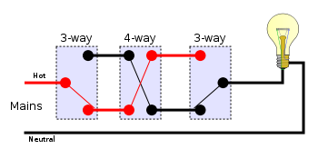
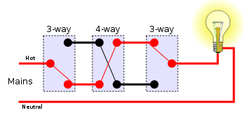
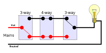
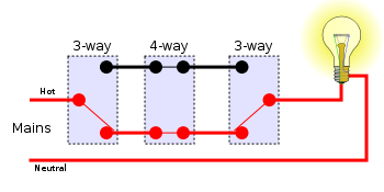
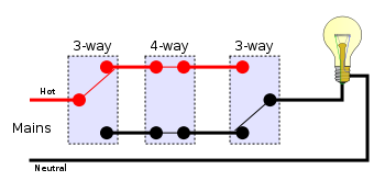
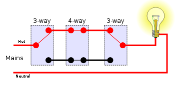
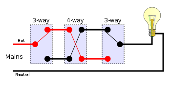
More than two locations
For more than two locations, two of the interconnecting wires must be passed through an intermediate switch, wired to swap them over. Any number of intermediate switches can be inserted, allowing for any number of locations. This requires two wires along the sequence of switches.Traveler system
Using the traveler system, there are eight possible combinations of switch positions: four with the light on and four with the light off. N.B. This diagram also uses the American electrical wiring names.| Off | On |
|---|---|
 |
 |
 |
 |
 |
 |
 |
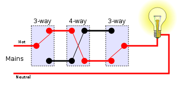 |
As mentioned above, the above circuit can be extended by using multiple 4-way switches between the 3-way switches to extend switching ability to any number of locations.
Low voltage control
At one time found in residences, from the 1930s to the early 1960s, and still used in office buildings, systems based on relayRelay
A relay is an electrically operated switch. Many relays use an electromagnet to operate a switching mechanism mechanically, but other operating principles are also used. Relays are used where it is necessary to control a circuit by a low-power signal , or where several circuits must be controlled...
s with low-voltage control circuits permit switching the power to lighting loads from an arbitrary number of locations. For each load a latching relay is used that maintains its on- or off-state, even if power to the building is interrupted. Mains power is wired through the relay to the load. Instead of running mains voltage to the switches, a safe, low voltage — typically 24 VAC — is connected to remote momentary toggle or rocker switches. The momentary switches are usually of form SPDT in (ON)-OFF-(ON) configuration. Pushing the switch actuator in one direction causes the relay contacts to close; pushing it in the opposite direction causes the relay contacts to open. Additional toggles can be wired in parallel as needed, and a master control can be added that turns all lights in the facility on or off simultaneously under the control of a timer or computer.
Residential use of such low voltage systems has become rare, and equipment for implementing them is not commonly carried by electrical suppliers, although it is still possible to find parts for maintaining existing installations. Multiway switching in residential applications is increasingly being implemented with power line signalling techniques, such as in the X10
X10 (industry standard)
X10 is an international and open industry standard for communication among electronic devices used for home automation, also known as domotics. It primarily uses power line wiring for signaling and control, where the signals involve brief radio frequency bursts representing digital information...
system, available since the 1980s, and newer hybrid wired/wireless systems, such as Insteon
INSTEON
Insteon is a system for connecting lighting switches and loads without extra wiring. INSTEON is a dual-band mesh home area networking topology employing AC-power lines and a radio-frequency protocol to communicate with devices...
. See Home automation
Home automation
Home automation is the residential extension of "building automation". It is automation of the home, housework or household activity. Home automation may include centralized control of lighting, HVAC , appliances, and other systems, to provide improved convenience, comfort, energy efficiency and...
.
Further reading
- Richard Day Wiring Multi Switches, page 85 and following, in Popular Science Jan 1987, Vol. 230, No. 1 ISSN 0161-7370