

Mohr's circle
Encyclopedia
Mohr's circle, named after Christian Otto Mohr, is a two-dimensional graphical representation of the state of stress at a point. The abscissa
Abscissa
In mathematics, abscissa refers to that element of an ordered pair which is plotted on the horizontal axis of a two-dimensional Cartesian coordinate system, as opposed to the ordinate...
,
 , and ordinate
Ordinate
In mathematics, ordinate refers to that element of an ordered pair which is plotted on the vertical axis of a two-dimensional Cartesian coordinate system, as opposed to the abscissa...
,
 , of each point on the circle
Circle
A circle is a simple shape of Euclidean geometry consisting of those points in a plane that are a given distance from a given point, the centre. The distance between any of the points and the centre is called the radius....
are the normal stress and shear stress components, respectively, acting on a particular cut plane with a unit vector
 with components
  . In other words, the circumference of the circle is the locus of points that represent the state of stress on individual planes at all their orientations.
Karl Culmann was the first to conceive a graphical representation for stresses while considering longitudinal and vertical stresses in horizontal beams during bending
Bending
In engineering mechanics, bending characterizes the behavior of a slender structural element subjected to an external load applied perpendicularly to a longitudinal axis of the element. The structural element is assumed to be such that at least one of its dimensions is a small fraction, typically...
. Mohr's contribution extended the use of this representation for both two- and three-dimensional stresses and developed a failure criterion based on the stress circle.
Other graphical methods for the representation of the stress state at a point include the Lame's stress ellipsoid
Lame's stress ellipsoid
Lame's stress ellipsoid is an alternative to Mohr's circle for the graphical representation of the stress state at a point. The surface of the ellipsoid represents the locus of the endpoints of all stress vectors acting on all planes passing through a given point in the continuum body...
and Cauchy's stress quadric.
Mohr's circle for two-dimensional stress states
A two-dimensional Mohr's circle can be constructed if we know the normal stresses ,
,  , and the shear stress
  . The following sign conventions are usually used:
- Tensile stresses (positive) are to the right.
- Compressive stresses (negative) are to the left.
- Clockwise shear stresses are plotted upward.
- Counterclockwise shear stresses are plotted downward.
The reason for the above sign convention is that, in engineering mechanics, the normal stresses are positive if they are outward to the plane of action (tension), and shear stresses are positive if they rotate clockwise about the point in consideration. In geomechanics
Geomechanics
Geomechanics is the geologic study of the behavior of soil and rock. The two main disciplines of geomechanics are soil mechanics and rock mechanics. The former deals with the behaviour of soil from a small scale to a landslide scale...
, i.e. soil mechanics
Soil mechanics
Soil mechanics is a branch of engineering mechanics that describes the behavior of soils. It differs from fluid mechanics and solid mechanics in the sense that soils consist of a heterogeneous mixture of fluids and particles but soil may also contain organic solids, liquids, and gasses and other...
and rock mechanics
Rock mechanics
Rock mechanics is the theoretical and applied science of the mechanical behaviour of rock and rock masses;also compared to the geology, it is that branch of mechanics concerned with the response of rock and rock masses to the force fields of their physical environment.Rock mechanics itself forms...
, however, normal stresses are considered positive when they are inward to the plane of action (compression), and shear stresses are positive if they rotate counterclockwise about the point in consideration.
To construct the Mohr circle of stress for a state of plane stress, or plane strain, first we plot two points in the
 space corresponding to the known stress components on both perpendicular planes, i.e.
  and
and  (Figure 1 and 2). We then connect points
  and
and  by a straight line and find the midpoint
  which corresponds to the intersection of this line with the
  axis. Finally, we draw a circle with diameter
  and centre at
  .
.The radius
 of the circle is
  , and the coordinates of its centre are
  .
.The principal stresses are then the abscissa
Abscissa
In mathematics, abscissa refers to that element of an ordered pair which is plotted on the horizontal axis of a two-dimensional Cartesian coordinate system, as opposed to the ordinate...
of the points of intersection of the circle with the
 axis (note that the shear stresses are zero for the principal stresses).
Drawing a Mohr's circle
.svg.png)
- First, the
 - and
- and  -axes of a Cartesian coordinate systemCartesian coordinate systemA Cartesian coordinate system specifies each point uniquely in a plane by a pair of numerical coordinates, which are the signed distances from the point to two fixed perpendicular directed lines, measured in the same unit of length...
are identified as the -axis and
  -axis, respectively.
 - Next, two points of the Mohr's circle are plotted. These are the points B (
 ,
,  ) and A (
 ,
,  ). The line connecting these two points is a diameter of the Mohr's circle.
 - The center of the Mohr's circle, O, is located where the diameter, AB, intersects the σ-axis. This point gives the average normal stress (σavg). The average normal stress can be read directly from a plot of the Mohr's circle. Alternatively, it can be calculated using
 .
. - The Mohr's circle intersects the
 axis at two points, C and E. The stresses at these two end points of the horizontal diameter are
  and
and  , the principal stresses. The point
  represents the maximum normal stress (σmax) and the point
  is the minimum normal stress (σmin). The equations for finding these values are

- Next we examine the points where the circle intersects the line parallel to
 -axis passing through the center of the circle, O. The vertical diameter of the circle passes through O (σavg) and goes up to positive
  and down to negative
  . The magnitudes of extreme values are equal to the radius of the Mohr's circle, but with different signs. The equation to find these extreme values of the shear stress is
 .
.
- The next value to determine is the angle that the plane of maximum normal stress makes with the
 -axis. Let us create a new
  -axis by drawing a line from the center of the Mohr circle, O, through point A. Let the angle between the
  -axis and the
  -axis be
  . If
. If  is the angle between the maximum normal stress and the
  -axis, then it can be shown that
  = 2
= 2 . The angle
  is found by:
 .
. - To find the angle that the direction that the plane of maximum shear stress makes with the
 -axis, we use the relation
 . It is important to pay attention to the use of these two equations as they look similar.
 - Often, the final step of the process is to also draw a square stress element indicating the orientations of the maximum normal and shear stresses; the normal stress element at an angle
 and the maximum shear stress element at an angle of
  .
.
The previous discussion assumes, implicitly, that there are two orthogonal directions and
and  that define a plane in which the stress components
  .
.  , and
, and  are known. It is also implicit that these stresses are known at a point
  in a continuum body under plane stress or plane strain. The Mohr circle, once drawn, can be used to find the components of the stress tensor for any other choice of orthogonal directions in the plane.
Stress components on an arbitrary plane
Using the Mohr circle one can find the stress components.svg.png)
 on any other plane with a different orientation
  that passes through point
  . For this, two approaches can be used:
- The first approach relies on the fact that the angle
 between two planes passing through
  is half the angle between the lines joining their corresponding stress points
  on the Mohr circle and the centre of the circle (Figure 1). In other words, the stresses
  acting on a plane at an angle
  counterclockwise to the plane on which
  acts is determined by traveling counterclockwise around the circle from the known stress point
  a distance subtending an angle
  at the centre of the circle (Figure 1).
 - The second approach involves the determination of a point on the Mohr circle called the pole or the origin of planes. Any straight line drawn from the pole will intersect the Mohr circle at a point that represents the state of stress on a plane inclined at the same orientation (parallel) in space as that line. Therefore, knowing the stress components
 and
and  on any particular plane, one can draw a line parallel to that plane through the particular coordinates
  and
and  on the Mohr circle and find the pole as the intersection of such line with the Mohr circle. As an example, let's assume we have a state of stress with stress components
  ,
,  , and
, and  , as shown on Figure 2. First, we can draw a line from point
  parallel to the plane of action of
  , or, if we choose otherwise, a line from point
  parallel to the plane of action of
  . The intersection of any of these two lines with the Mohr circle is the pole. Once the pole has been determined, to find the state of stress on a plane making an angle
  with the vertical, or in other words a plane having its normal vector forming an angle
  with the horizontal plane, then we can draw a line from the pole parallel to that plane (See Figure 2). The normal and shear stresses on that plane are then the coordinates of the point of intersection between the line and the Mohr circle.
Mohr's circle for a general three-dimensional state of stresses
To construct the Mohr's circle for a general three-dimensional case of stresses at a point, the values of the principal stresses and their principal directions
  must be first evaluated.
Considering the principal axes as the coordinate system, instead of the general ,
,  ,
,  coordinate system, and assuming that
  , then the normal and shear components of the stress vector
  , for a given plane with unit vector
  , satisfy the following equations

Knowing that , we can solve for
  ,
,  ,
,  , using the Gauss elimination method which yields
Since , and
, and  is non-negative, the numerators from the these equations satisfy
 as the denominator
  and
and 
 as the denominator
  and
and 
 as the denominator
  and
and 
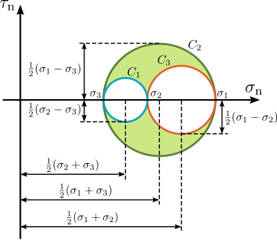
These expressions can be rewritten as
which are the equations of the three Mohr's circles for stress ,
,  , and
, and  , with radii
  ,
,  , and
, and  , and their centres with coordinates
  ,
,  ,
,  , respectively.
These equations for the Mohr's circles show that all admissible stress points lie on these circles or within the shaded area enclosed by them (see Figure 3). Stress points
  satisfying the equation for circle
  lie on, or outside circle
  . Stress points
  satisfying the equation for circle
  lie on, or inside circle
  . And finally, stress points
  satisfying the equation for circle
  lie on, or outside circle
  .
.
External links
- The next value to determine is the angle that the plane of maximum normal stress makes with the
- Next we examine the points where the circle intersects the line parallel to