

Mismatch loss
Encyclopedia
Mismatch loss in transmission line
theory is the amount of power expressed in decibels that will not be available on the output due to impedance mismatches and reflections. A transmission line that is properly terminated, that is, terminated with the same impedance as that of the characteristic impedance
of the transmission line, will have no reflections and therefore no mismatch loss. Mismatch loss represents the amount of power wasted in the system. It can also be thought of as the amount of power gained if the system was perfectly matched. Impedance matching
is an important part of RF system design; however, in practice there will likely be some degree of mismatch loss. In real systems, relatively little loss is due to mismatch loss and is often on the order of 1dB.

where
 = incident power
 = reflected power
 = delivered power (also called the accepted power)
The fraction of incident power delivered to the load is

where
 is the magnitude of the reflection coefficient
. Note that as the reflection coefficient approches zero, power to the load is maximized.
If the reflection coefficient is known, mismatch can be calculated by
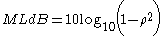
In terms of the voltage standing wave ratio (VSWR):

. Other common RF system components such as filters
, attenuators, splitters, and combiners will generate some amount of mismatch loss. While completely eliminating mismatch loss in these components is near impossible, mismatch loss contributions by each component can be minimized by selecting quality components for use in a well designed system.
The general case for calculating mismatch error (ME) is:
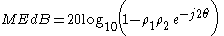
where is the complex phase change due to the second reflection
Transmission line
In communications and electronic engineering, a transmission line is a specialized cable designed to carry alternating current of radio frequency, that is, currents with a frequency high enough that its wave nature must be taken into account...
theory is the amount of power expressed in decibels that will not be available on the output due to impedance mismatches and reflections. A transmission line that is properly terminated, that is, terminated with the same impedance as that of the characteristic impedance
Characteristic impedance
The characteristic impedance or surge impedance of a uniform transmission line, usually written Z_0, is the ratio of the amplitudes of a single pair of voltage and current waves propagating along the line in the absence of reflections. The SI unit of characteristic impedance is the ohm...
of the transmission line, will have no reflections and therefore no mismatch loss. Mismatch loss represents the amount of power wasted in the system. It can also be thought of as the amount of power gained if the system was perfectly matched. Impedance matching
Impedance matching
In electronics, impedance matching is the practice of designing the input impedance of an electrical load to maximize the power transfer and/or minimize reflections from the load....
is an important part of RF system design; however, in practice there will likely be some degree of mismatch loss. In real systems, relatively little loss is due to mismatch loss and is often on the order of 1dB.
Calculation
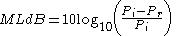
Mismatch loss (ML) is the ratio of incident power to the difference between incident and reflected power:where
= incident power = reflected power = delivered power (also called the accepted power)The fraction of incident power delivered to the load is
where
is the magnitude of the reflection coefficientReflection coefficient
The reflection coefficient is used in physics and electrical engineering when wave propagation in a medium containing discontinuities is considered. A reflection coefficient describes either the amplitude or the intensity of a reflected wave relative to an incident wave...
. Note that as the reflection coefficient approches zero, power to the load is maximized.
If the reflection coefficient is known, mismatch can be calculated by
In terms of the voltage standing wave ratio (VSWR):
Sources of mismatch loss
Any component of the transmission line that has an input and output will contribute to the overall mismatch loss of the system. For example, in mixers mismatch loss occurs when there is an impedance mismatch between the RF port and IF port of the mixer. This is one of the principal reasons for losses in mixers. Likewise, a large amount of the loss in amplifiers comes from the mismatch between the input and output. Consequently, not all of the available power generated by the amplifier gets transferred to the load. This is most important in antenna systems where mismatch loss in the transmitting and receiving antenna directly contributes to the losses the system—including the system noise figureNoise figure
Noise figure is a measure of degradation of the signal-to-noise ratio , caused by components in a radio frequency signal chain. The noise figure is defined as the ratio of the output noise power of a device to the portion thereof attributable to thermal noise in the input termination at standard...
. Other common RF system components such as filters
Filter (signal processing)
In signal processing, a filter is a device or process that removes from a signal some unwanted component or feature. Filtering is a class of signal processing, the defining feature of filters being the complete or partial suppression of some aspect of the signal...
, attenuators, splitters, and combiners will generate some amount of mismatch loss. While completely eliminating mismatch loss in these components is near impossible, mismatch loss contributions by each component can be minimized by selecting quality components for use in a well designed system.
Mismatch error
If there are two or more components in cascade as is often the case, the resultant mismatch loss is not only due to the mismatches from the individual components, but also from how the reflections from each component combine with each other. The overall mismatch loss cannot be calculated by just adding up the individual loss contributions from each component. The difference between the sum of the mismatch loss in each component and total mismatch loss due to the interactions of the reflections is known as mismatch error. Depending on how the multiple reflections combine, the overall system loss may be lower or higher than the sum of the mismatch loss from each component. Mismatch error occurs in pairs as the signal reflects off of each mismatched component. So for the example in Figure 3, there are mismatch errors generated by each pair of components. The mismatch uncertainty increases as the frequency increases, and in wide-band applications. The phasing of the reflections makes it particularly harder to model.The general case for calculating mismatch error (ME) is:
where
is the complex phase change due to the second reflection