
Enigma rotor details
Encyclopedia
This article contains technical details about the rotors of the Enigma machine
.
Understanding the way the machine encrypts requires taking into account the current position of each rotor, the ring setting and its internal wiring.
As an example, let us take rotor type I without any ring setting offset. You can see that an A is encoded as an E, a B encoded as a K, and a K is encoded as an N. Notice that every letter is encoded into another.
In the case of the reflectors, we take Wide B where an A is returned as a Y and the Y is returned as an A. Notice that the wirings are connected as a loop between two letters.
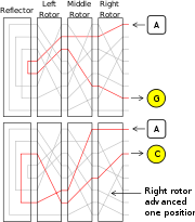
When a rotor has stepped, you must take into account the offset to know what the output is, and where it enters the next rotor.
If for example rotor I is in the B-position, an A enters at the letter B which is wired to the K. Because of the offset this K enters the next rotor in the J position.
With the rotors I, II and III (from left to right), wide B-reflector, all ring settings in A-position, and start position AAA, typing AAAAA will produce the encoded sequence BDZGO.
The ring setting will rotate the wiring. Where rotor I in the A-position normally encodes an A into an E, with a ring setting offset B-02 it will be encoded into K
As mentioned before these encodings only happen after the key is pressed and the rotor has turned. Tracing the signal on the rotors AAA is therefore only possible if a key is pressed while the rotors were in the position AAZ.
With the rotors I, II, III (from left to right), wide B-reflector, all ring settings in B-position, and start position AAA, typing AAAAA will produce the encoded sequence EWTYX.
Terminology
Technical comments related to Enigma modifications 1939-1945.
article.
Enigma machine
An Enigma machine is any of a family of related electro-mechanical rotor cipher machines used for the encryption and decryption of secret messages. Enigma was invented by German engineer Arthur Scherbius at the end of World War I...
.
Understanding the way the machine encrypts requires taking into account the current position of each rotor, the ring setting and its internal wiring.
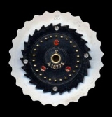
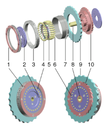
Physical design of rotors
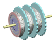
| Exploded view of an Enigma rotor | Three rotors in sequence | |
|---|---|---|
 |
|
 |
Rotor electrical view
The rotor offset
In order to understand the effect of rotation on the rotors we demonstrate this by some examples.As an example, let us take rotor type I without any ring setting offset. You can see that an A is encoded as an E, a B encoded as a K, and a K is encoded as an N. Notice that every letter is encoded into another.
In the case of the reflectors, we take Wide B where an A is returned as a Y and the Y is returned as an A. Notice that the wirings are connected as a loop between two letters.
When a rotor has stepped, you must take into account the offset to know what the output is, and where it enters the next rotor.
If for example rotor I is in the B-position, an A enters at the letter B which is wired to the K. Because of the offset this K enters the next rotor in the J position.
With the rotors I, II and III (from left to right), wide B-reflector, all ring settings in A-position, and start position AAA, typing AAAAA will produce the encoded sequence BDZGO.
The ring setting
The ring settings, or Ringstellung, are used to change the position of the internal wiring relative to the rotor. They do not change the notch or the alphabet ring on the exterior. Those are fixed to the rotor. Changing the ring setting will therefore change the positions of the wiring, relative to the turnover-point and start position.The ring setting will rotate the wiring. Where rotor I in the A-position normally encodes an A into an E, with a ring setting offset B-02 it will be encoded into K
As mentioned before these encodings only happen after the key is pressed and the rotor has turned. Tracing the signal on the rotors AAA is therefore only possible if a key is pressed while the rotors were in the position AAZ.
With the rotors I, II, III (from left to right), wide B-reflector, all ring settings in B-position, and start position AAA, typing AAAAA will produce the encoded sequence EWTYX.
Rotor wiring tables
This table shows how the internal wiring connects the right side of the rotor (with the springloaded contacts) to the left side. Each rotor is a simple substitution cipher. The letters are listed as connected to alphabet order. If the first letter of a rotor is E, this means that the A is wired to the E. This does not mean that E is wired to A. This looped wiring is only the case with the reflectors.Terminology
- The reflector is also known as the reversing drum or, from the German, the Umkehrwalze or UKW.
| Rotor # | ABCDEFGHIJKLMNOPQRSTUVWXYZ | Date Introduced | Model Name & Number |
|---|---|---|---|
| IC | DMTWSILRUYQNKFEJCAZBPGXOHV | 1924 | Commercial Enigma A, B |
| IIC | HQZGPJTMOBLNCIFDYAWVEUSRKX | 1924 | Commercial Enigma A, B |
| IIIC | UQNTLSZFMREHDPXKIBVYGJCWOA | 1924 | Commercial Enigma A, B |
| Rotor # | ABCDEFGHIJKLMNOPQRSTUVWXYZ | Date Introduced | Model Name & Number |
| I | JGDQOXUSCAMIFRVTPNEWKBLZYH | 7 February 1941 | German Railway (Rocket) |
| II | NTZPSFBOKMWRCJDIVLAEYUXHGQ | 7 February 1941 | German Railway (Rocket) |
| III | JVIUBHTCDYAKEQZPOSGXNRMWFL | 7 February 1941 | German Railway (Rocket) |
| UKW | QYHOGNECVPUZTFDJAXWMKISRBL | 7 February 1941 | German Railway (Rocket) |
| ETW | QWERTZUIOASDFGHJKPYXCVBNML | 7 February 1941 | German Railway (Rocket) |
| Rotor # | ABCDEFGHIJKLMNOPQRSTUVWXYZ | Date Introduced | Model Name & Number |
| I-K | PEZUOHXSCVFMTBGLRINQJWAYDK | February 1939 | Swiss K |
| II-K | ZOUESYDKFWPCIQXHMVBLGNJRAT | February 1939 | Swiss K |
| III-K | EHRVXGAOBQUSIMZFLYNWKTPDJC | February 1939 | Swiss K |
| UKW-K | IMETCGFRAYSQBZXWLHKDVUPOJN | February 1939 | Swiss K |
| ETW-K | QWERTZUIOASDFGHJKPYXCVBNML | February 1939 | Swiss K |
| Rotor # | ABCDEFGHIJKLMNOPQRSTUVWXYZ | Date Introduced | Model Name & Number |
| I | EKMFLGDQVZNTOWYHXUSPAIBRCJ | 1930 | Enigma I |
| II | AJDKSIRUXBLHWTMCQGZNPYFVOE | 1930 | Enigma I |
| III | BDFHJLCPRTXVZNYEIWGAKMUSQO | 1930 | Enigma I |
| IV | ESOVPZJAYQUIRHXLNFTGKDCMWB | DEC 1938 | M3 Army |
| V | VZBRGITYUPSDNHLXAWMJQOFECK | DEC 1938 | M3 Army |
| VI | JPGVOUMFYQBENHZRDKASXLICTW | 1939 | M3 & M4 Naval (FEB 1942) |
| VII | NZJHGRCXMYSWBOUFAIVLPEKQDT | 1939 | M3 & M4 Naval (FEB 1942) |
| VIII | FKQHTLXOCBJSPDZRAMEWNIUYGV | 1939 | M3 & M4 Naval (FEB 1942) |
| Rotor # | ABCDEFGHIJKLMNOPQRSTUVWXYZ | Date Introduced | Model Name & Number |
| Beta | LEYJVCNIXWPBQMDRTAKZGFUHOS | Spring 1941 | M4 R2 |
| Gamma | FSOKANUERHMBTIYCWLQPZXVGJD | Spring 1942 | M4 R2 |
| Reflector A | EJMZALYXVBWFCRQUONTSPIKHGD | ||
| Reflector B | YRUHQSLDPXNGOKMIEBFZCWVJAT | ||
| Reflector C | FVPJIAOYEDRZXWGCTKUQSBNMHL | ||
| Reflector B Thin | ENKQAUYWJICOPBLMDXZVFTHRGS | 1940 | M4 R1 (M3 + Thin) |
| Reflector C Thin | RDOBJNTKVEHMLFCWZAXGYIPSUQ | 1940 | M4 R1 (M3 + Thin) |
| ETW | ABCDEFGHIJKLMNOPQRSTUVWXYZ | Enigma I | |
Technical comments related to Enigma modifications 1939-1945.
Swiss K
- In 1941 it became known to the Swiss that some of their Enigma traffic was being read by the French. It was decided to make some design modifications.
- One of the modifications consisted in modifying the wheel stepping on the Swiss Army machine. The slow, left-hand wheel was made stationary during operation while the second wheel stepped with every key stroke.
- The third wheel and the UKW would step in the normal fashion with Enigma stepping for the third wheel.
- The stationary but rotatable left-hand wheel was meant to make up for the missing stecker connections on the commercial machine.
- Swiss Army Enigma machines were the only machines modified. The surviving Swiss Air Force machines do not show any signs of modification. Machines used by the diplomatic service apparently were not altered either.
Turnover positions
In this table the turnover point of each rotor is listed. For more details on how the rotors move, please check the Stepping motion section and the remarks on double-stepping in the EnigmaEnigma machine
An Enigma machine is any of a family of related electro-mechanical rotor cipher machines used for the encryption and decryption of secret messages. Enigma was invented by German engineer Arthur Scherbius at the end of World War I...
article.
| Rotor | Notch | Effect |
|---|---|---|
| I | Q | If rotor steps from Q to R, the next rotor is advanced |
| II | E | If rotor steps from E to F, the next rotor is advanced |
| III | V | If rotor steps from V to W, the next rotor is advanced |
| IV | J | If rotor steps from J to K, the next rotor is advanced |
| V | Z | If rotor steps from Z to A, the next rotor is advanced |
| VI, VII, VIII | Z+M | if rotor steps from Z to A, or from M to N the next rotor is advanced |
Normalized Enigma sequences
In the following examples you can observe a normal step sequence and a double step sequence. The used rotors are (from left to right) I, II, III, with turnovers on Q, E and V. It is the right rotor's behavior we observe here (turnover V).- Normal sequence:
- AAU — normal step of right rotor
- AAV — right rotor (III) goes in V—notch position
- ABW — right rotor takes middle rotor one step further
- ABX — normal step of right rotor
- Double step sequence:
- ADU — normal step of right rotor
- ADV — right rotor (III) goes in V—notch position
- AEW — right rotor steps, takes middle rotor (II) one step further, which is now in its own E—notch position
- BFX — normal step of right rotor, double step of middle rotor, normal step of left rotor
- BFY — normal step of right rotor
See also
Several unknown models of the Enigma machine have been discovered [...]- http://home.comcast.net/~dhhamer/downloads/enigvar2.pdf