

Copper cable certification
Encyclopedia
Telecommunications Industry Association
The Telecommunications Industry Association is accredited by the American National Standards Institute to develop voluntary, consensus-based industry standards for a wide variety of ICT products, and currently represents nearly 400 companies...
(TIA) or International Organization for Standardization
International Organization for Standardization
The International Organization for Standardization , widely known as ISO, is an international standard-setting body composed of representatives from various national standards organizations. Founded on February 23, 1947, the organization promulgates worldwide proprietary, industrial and commercial...
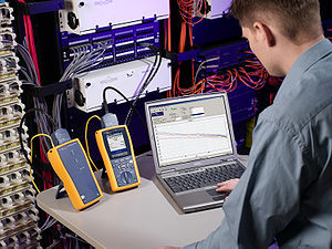
(ISO) standards. These tests are done using a certification-testing tool, which provide “Pass” or “Fail” information. While certification can be performed by the owner of the network, certification is primarily done by datacom contractors. It is this certification that allows the contractors to warranty their work.
Need for certification
Installers who need to prove to the network owner that the installation has been done correctly and meets TIA or ISO standards need to certify their work. Network owners who want to guarantee that the infrastructure is capable of handling a certain application (e.g. Voice over Internet) will use a tester to certify the network infrastructure. In some cases, these testers are used to pinpoint specific problems. Certification tests are vital if there is a discrepancy between the installer and network owner after an installation has been performed.The Standards
The performance tests and their procedures have been defined in the ANSI/TIA/EIA-568-B.1 standard and the ISO/IEC 11801ISO/IEC 11801
International standard ISO/IEC 11801 specifies general-purpose telecommunication cabling systems that are suitable for a wide range of applications . It covers both balanced copper cabling and optical fibre cabling...
standard. The TIA standard defines performance in categories (Cat 3
Category 3 cable
Category 3 cable, commonly known as Cat 3 or station wire, is an unshielded twisted pair cable designed to reliably carry data up to 10 Mbit/s, with a possible bandwidth of 16 MHz...
, Cat 5e, Cat 6) and the ISO defines classes (Class C, D, E, and F). These standards define the procedure to certify that an installation meets performance criteria in a given category or class.
The significance of each category or class is the limit values of which the Pass/Fail and frequency ranges are measured; Cat 3 and Class C (no longer used) test and define communication with 16 MHz bandwidth, Cat 5e and Class D with 100 MHz bandwidth, Cat 6 and Class E up to 250 MHz, and Cat 7 and Class F with a frequency range through 600 MHz.
The standards also define that data from each test result must be collected and stored in either print or electronic format for future inspection.
The Tests
| Test Parameter | TIA-568-B | ISO 11801:2002 |
|---|---|---|
| Wiremap | Pass/Fail | Pass/Fail |
| Propagation Delay | Pass/Fail | Pass/Fail |
| Delay Skew | Pass/Fail | Pass/Fail |
| Cable Length | Pass/Fail | Information only |
| Insertion Loss (IL) | Pass/Fail | Pass/Fail |
| Return Loss (RL) | Pass/Fail (except Cat3) | Pass/Fail |
| Near-End Crosstalk (NEXT) | Pass/Fail | Pass/Fail |
| Power Sum NEXT (PSNEXT) | Pass/Fail | Pass/Fail |
| Equal-Level Far-End Crosstalk (ELFEXT) | Pass/Fail | Pass/Fail |
| Power Sum ELFEXT (PSELFEXT) | Pass/Fail | Pass/Fail |
| Attenuation-to-Crosstalk Ratio (ACR) | Information only | Pass/Fail (except Class C) |
| Power sum ACR (PSACR) | Information only | Pass/Fail (except Class C) |
| DC Loop Resistance | Pass/Fail |
Wiremap
The Wiremap test is used to identify physical errors of the installation; proper pin termination at each end, shorts between any two or more wires, continuity to the remote end, split pairSplit pair
A split pair is a wiring error where two connections that are supposed to be connected using the two wires of a twisted pair are instead connected using two wires from different pairs...
s, crossed pairs, reversed pairs, and any other mis-wiring.
See TIA/EIA-568-B for wiring diagram.
Propagation Delay
The Propagation Delay test tests for the time it takes for the signal to be sent from one end and received by the other end.
Delay Skew
The Delay Skew test tests for the difference in propagation delay between the fastest and slowest set of wire pairs. An ideal skew is between 25 and 50 nanoseconds over a 100 meter cable. The lower this skew the better, less than 25 ns is excellent, but 45 to 50 ns is marginal.
Cable Length
The Cable Length test verifies that the cable from the transmitter to receiver does not exceed the maximum recommended distance of 100 meters in a 10BASE-T/100BASE-TX/1000BASE-T network.Insertion Loss
Insertion lossInsertion loss
In telecommunications, insertion loss is the loss of signal power resulting from the insertion of a device in a transmission line or optical fiber and is usually expressed in decibels ....
, also referred to as attenuation
Attenuation
In physics, attenuation is the gradual loss in intensity of any kind of flux through a medium. For instance, sunlight is attenuated by dark glasses, X-rays are attenuated by lead, and light and sound are attenuated by water.In electrical engineering and telecommunications, attenuation affects the...
, refers to the loss of signal strength at the far end of a line compared to the signal that was introduced into the line. This loss is due to the electrical impedance of the copper cable, the loss of energy through the cable insulation and the impedance caused by the connectors. Insertion loss is usually expressed in decibels dB with a minus sign. Insertion loss increases with distance and frequency. For every 6dB of loss, the original signal will be half the original amplitude.
Decibels vs. Voltage
| dB | Voltage Ratio | dB | Voltage Ratio | dB | Voltage Ratio | dB | Voltage Ratio | |
|---|---|---|---|---|---|---|---|---|
| 0 | 1V | -13 | .224 | -6 | .500 | -19 | .112 | |
| -1 | .891 | -14 | .200 | -7 | .447 | -20 | .100 | |
| -2 | .794 | -15 | .178 | -8 | .398 | -30 | .032 | |
| -3 | .707 | -16 | .158 | -9 | .355 | -40 | .010 | |
| -4 | .631 | -17 | .141 | -10 | .316 | -50 | .003 | |
| -5 | .562 | -18 | .125 | -11 | .282 | -60 | .001 | |
| -12 | .250 | -80 | .000 |
Return Loss
Return Loss is the measurement (in dB) of the amount of signal that is reflected back toward the transmitter. The reflection of the signal is caused by the variations of impedance in the connectors and cable and is usually attributed to a poorly terminated wire. The greater the variation in impedance, the greater the return loss reading. If 3 pairs of wire pass by a substantial amount, but the 4 pair barely passes, it usually is an indication of a bad crimp or bad connection at the RJ45 plug. Return loss is usually not significant in the loss of a signal, but rather signal jitter.Near-End Crosstalk (NEXT)
Near-End Crosstalk (NEXT) is an error condition that describes the occurrence of a signal from one wire pair radiating to and interfering with the signal of another wire pair. It is the difference in amplitude (in dB) between a transmitted signal and the crosstalk received on other cable pairs at the same end of the cabling. Higher NEXT values correspond to better cabling performance. A higher value is desirable as it would indicate that the power transmitted is greater in magnitude than the power induced onto another wire pair given that the NEXT measurement is simply a difference calculation. NEXT must be measured from each pair to each other pair in twisted pair cabling and from each end of the connection. NEXT is measured 30 meters (about 98 feet) from the injector / generator. Lower near end crosstalk values correspond to higher overall circuit performance. High NEXT values on a UTP LAN that will be using an older signaling standard (IEEE 802.3IEEE 802.3
IEEE 802.3 is a working group and a collection of IEEE standards produced by the working group defining the physical layer and data link layer's media access control of wired Ethernet. This is generally a local area network technology with some wide area network applications...
i and earlier) are particularly detrimental.
It could be an indication of improper termination.
Power Sum NEXT (PSNEXT)
Power Sum NEXT (PSNEXT) is the sum of NEXT values from 3 wire pairs as they affect the other wire pair. The combined effect of NEXT can be very detrimental to the signal.The Equal-Level Far-End Crosstalk (ELFEXT)
The Equal-Level Far-End Crosstalk (ELFEXT) test measures Far-End Crosstalk (FEXT). FEXT is very similar to NEXT, but happens at the receiver side of the connection. Due to impedance on the line, crosstalk diminishes the signal as it gets further away from the transmitter. Because of this, FEXT is usually less detrimental to a signal than NEXT, but still important nonetheless.Power Sum ELFEXT (PSELFEXT)
Power Sum ELFEXT (PSELFEXT) is the sum of FEXT values from 3 wire pairs as they affect the other wire pair.Attenuation-to-Crosstalk ratio (ACR)
Attenuation-to-Crosstalk ratio (ACR) is the difference between the signal attenuation produced and NEXT and is measured in decibels (dB). The ACR indicates how much stronger the attenuated signal is than the crosstalk at the destination (receiving) end of a communications circuit. The ACR figure must be at least several decibels for proper performance. If the ACR is not large enough, errors will be frequent. In many cases, even a small improvement in ACR can cause a dramatic reduction in the bit error rate. Sometimes it may be necessary to switch from un-shielded twisted pair (UTP) cable to shielded twisted pair (STP) in order to increase the ACR.Power Sum ACR (PSACR)
Power Sum ACR (PSACR) done in the same way as ACR, but using the PSNEXT value in the calculation rather than NEXT.DC Loop Resistance
DC Loop Resistance measures the total resistance through one wire pair looped at one end of the connection. This will increase with the length of the cable. DC resistance usually has less effect on a signal than insertion loss, but plays a major role if power over EthernetPower over Ethernet
Power over Ethernet or PoE technology describes a system to pass electrical power safely, along with data, on Ethernet cabling. The IEEE standard for PoE requires category 5 cable or higher for high power levels, but can operate with category 3 cable for low power levels...
is required. Also measured in ohms is the characteristic impedance
Characteristic impedance
The characteristic impedance or surge impedance of a uniform transmission line, usually written Z_0, is the ratio of the amplitudes of a single pair of voltage and current waves propagating along the line in the absence of reflections. The SI unit of characteristic impedance is the ohm...
of the cable, which is independent of the cable length.