

Amtrak's 60 Hz Traction Power System
Encyclopedia
Amtrak
The National Railroad Passenger Corporation, doing business as Amtrak , is a government-owned corporation that was organized on May 1, 1971, to provide intercity passenger train service in the United States. "Amtrak" is a portmanteau of the words "America" and "track". It is headquartered at Union...
operates a 60 Hz Traction Power System along the Northeast Corridor
Northeast Corridor
The Northeast Corridor is a fully electrified railway line owned primarily by Amtrak serving the Northeast megalopolis of the United States from Boston in the north, via New York to Washington, D.C. in the south, with branches serving other cities...
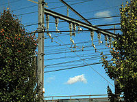
between New Haven, CT and Boston, MA. This system was built in the late 1990s and supplies locomotives with catenary
Overhead lines
Overhead lines or overhead wires are used to transmit electrical energy to trams, trolleybuses or trains at a distance from the energy supply point...
power at 25 kV, 60 Hz. This system is also sometimes known as the Northend Electrification.
History
System Architecture
In Amtrak's architecture, the most basic unit of continuous catenary is called an Elementary Electrical Section. Elementary Electrical Sections generally consist of the catenary (also called the contact or trolley wire) and associated feeder above one section of track in the interval between interlockings. Track interlockings are the natural boundary for elementary section, and the catenary are separated by section breaks at the interlockings. Motor-operated air switches bridge the section breaks at interlockings and connect the catenary and feeder continuously along one track for the entire length of an Electrical Section.An Electrical Section is the collection of elementary electrical sections which lie between a Substation and a Switching Station. Substations are the supply points of the system where utility supplied single phase power is transformed and distributed in either direction along the line. The substation supplies power in both directions along the line, but these two sections are electrically independent. The section breaks, air switches, and paralleling stations between the substation and the terminating switching station comprise an Electrical Section. There are a total of eight Electrical Sections in the system; two for each substation.
Power flows from the substation directly through the catenary wire to the pantograph of consuming locomotives. Power also flows through the feeder wire which is suspended from the catenary supports above the catenary contact wire. Power is transferred from the feeder wire to the contact wire by periodically spaced Paralleling Stations. The Paralleling Stations connect north and south contact wires and north and south feeder wires to the terminals of the stations autotransformer. Both the feeder and contact wire are energized at 25 kV with respect to ground, but they are 50 kV with respect to each other since they are powered by the output of a center-tap to ground substation transformer. The paralleling stations thus distribute a given locomotive's load across the four wires of the combined two-track autotransformer system rather than just the single contact wire.
Substations
There are four Substations between New Haven and Boston:- Branford, CT;
- New London,CT;
- Warwick, RI; and
- Sharon, MA.
Each station contains two 115 kV (single phase) to 50 kV (single phase with center tap) transformers to convert the utility supplied transmission voltage to 50kV traction voltage. Output circuit breakers, and a capacitor based filter network are installed. The filter banks suppress the high frequency (that is anything above 60 Hz) harmonics on the catenary lines generated by locomotives' solid-state traction motor inverters. The filters also provide reactive power support and correct for power factor. Amtrak's 60 Hz electrification distributes power using ±25 kV from ground via a center tap of the 115/50 kV transformers. This system is also known as 2 x 25 kV.
Switching Stations
Three Switching Stations are located along the line which separate the different electrical sections (power zones):- Westbrook, CT;
- Richmond, RI; and
- Norton, MA.
The switching stations contain three autotransformer
Autotransformer
An autotransformer is an electrical transformer with only one winding. The auto prefix refers to the single coil acting on itself rather than any automatic mechanism. In an autotransformer portions of the same winding act as both the primary and secondary. The winding has at least three taps where...
s similar to the paralleling stations (which have one), and also have additional circuit breakers to allow segmentation of catenary and cross-connection between power zones.
Electrical sections encompass both tracks between a substation and the adjacent switching stations. Normally no power flows from one side of a switching station to the other side; it is like two adjacent paralleling stations which serve different electrical sections. In the event that a substation is taken out of service, switching stations have additional circuit breakers which allow feeding an electrical section from the adjacent section.
Since switching stations, like substations, normally separate electrical sections with different supply sources (and thus different phase or voltage), a neutral section always occupies the track between the two electrical sections.
In the event of a fault in one elementary electrical section, the switching station can 'back-feed' the far portion of the affected track from the non-affected track, which the supplying substation feeds the near end.
Paralleling Stations
Eighteen Paralleling Stations are located at approximately six mile intervals along the line. Each contains a single autotransformer (with the exception of Roxbury, which has two), automatic circuit breakers, motor-operated air switches, and a control shed. The autotransformers are rated at 10 MVA, 1.2% impedance, two winding, 27.5 kV.Each paralleling station bus is connected to both north and south track catenary and feeder lines via automatic circuit breakers. The autotransformer is connected to the bus bars by an additional circuit breaker. The track breakers at the paralleling stations trip on sensing no-voltage. Thus when a line fault causes the supplying substation breakers to trip, the paralleling stations also trip. This action separates the two tracks from one another electrically and allows the substation to automatically restore one of the tracks (the non-faulted one). After a variable time delay (to reduce simultaneous inrush current), over-voltage relays will re-shut the track circuit breakers on the non-faulted track.
List of Stations
| MP | Location | Type | Coordinates | Comments |
|---|---|---|---|---|
| 228.49 | Boston (South) | N/A | End of Electrification | |
| 226.12 | Roxbury | Paralleling Station | 42.3331°N 71.0937°W | |
| 219.08 | Readville | Paralleling Station | 42.2365°N 71.1343°W | |
| 212.36 | Sharon | Substation | 42.1442°N 71.1642°W | |
| 204.98 | East Foxboro | Paralleling Station | 42.0456°N 71.2107°W | |
| 198.68 | Norton | Switching Station | 41.969°N 71.2652°W | |
| 193.41 | Attleboro | Paralleling Station | 41.903555°N 71.322914°W | |
| 187.60 | Providence | Paralleling Station | 41.860604°N 71.406251°W | |
| 181.89 | Elmwood | Paralleling Station | 41.798065°N 71.42868°W | |
| 176.94 | Warwick | Substation | 41.732459°N 71.440597°W | |
| 169.82 | East Greenwich | Paralleling Station | 41.634505°N 71.463999°W | |
| 161.81 | Exeter | Paralleling Station | 41.525942°N 71.518782°W | |
| 157.15 | Kingston | Paralleling Station | 41.475541°N 71.57462°W | |
| 150.15 | Richmond | Switching Station | 41.437637°N 71.689892°W | |
| 145.19 | Bradford | Paralleling Station | 41.394712°N 71.760969°W | |
| 139.97 | State Line | Paralleling Station | 41.3644°N 71.8403°W | |
| 134.70 | Stonington | Paralleling Station | 41.3403°N 71.9254°W | |
| 129.50 | Noank | Paralleling Station | 41.3234°N 71.9984°W | |
| 123.56 | New London | Substation | 41.3629°N 72.093°W | Transformers are grade separated from roadbed; catenary feeders run underground. |
| 117.54 | Millstone | Paralleling Station | 41.3164°N 72.1644°W | |
| 109.30 | Old Lyme | Paralleling Station | 41.2966°N 72.3044°W | |
| 103.10 | Westbrook | Switching Station | 41.2900°N 72.4112°W | |
| 98.87 | Grove Beach | Paralleling Station | 41.2768°N 72.4875°W | |
| 92.19 | Madison | Paralleling Station | 41.2840°N 72.6112°W | |
| 86.10 | Leetes Island | Paralleling Station | 41.2655°N 72.7250°W | |
| 78.96 | Branford | Substation | 41.2841°N 72.8537°W | Transformers located N. of I-95. |
| 73.6 | Mill River Interlocking | N/A | 41.311281°N 72.911775°W | End of 25 kV, 60 Hz System |
See also
- 25 kV AC railway electrification
- Amtrak's 25 Hz Traction Power System operates along the southern portions of the Northeast Corridor
- SEPTA's 25 Hz Traction Power SystemSEPTA's 25 Hz Traction Power SystemSEPTA operates a 25 Hz traction power system in the vicinity of Philadelphia, Pennsylvania that it inherited from the Reading Railroad. This system is separate but similar to the system designed by the Pennsylvania Railroad which is now operated by Amtrak. SEPTA's trains can run over either...
- List of current systems for electric rail traction
- Overhead linesOverhead linesOverhead lines or overhead wires are used to transmit electrical energy to trams, trolleybuses or trains at a distance from the energy supply point...
Further reading
- Agarwal, K. K. "Automatic fault location and isolation system for the electric traction overhead lines", Railroad Conference, 2002 ASME/IEEE Joint, p. 117, 2002. DOI: 10.1109/RRCON.2002.1000103.
- Audit Report of Amtrak's High Speed Rail Electrification Project, US Department of Transportation: Federal Railroad Administration, December 1999. Retrieved 12/26/2010.
- Chance, E.E. "System Compatibility of the HST", Railroad Conference, 1997., Proceedings of the 1997 IEEE/ASME Joint, pp 1-9, 1997. DOI: 10.1109/RRCON.1997.581346.
- EMF Monitoring on Amtrak's Northeast Corridor: Post-Electrification Measurements and Analysis, US Department of Transportation: Federal Railroad Administration, October 2006. Retrieved 12/26/2010.
- Natarajan, R.; Imece, A.F.; Popoff, J.; Agarwal, K.; Meliopoulos, S. "Approach to the analysis of Amtrak's systemwide grounding of the Northend Electrification Project", Power Engineering Society Summer Meeting, 1999, Vol 1, pp. 451-456. DOI: 10.1109/PESS.1999.784390.
- Sutherland, et al. Analysis of Harmonics, Flicker and Unbalance of Time-Varying Single-Phase Traction Loads on a Three-Phase System, Paper No. IPST05 - 091. Retrieved 12/26/2010.