
Wilson current source
Encyclopedia
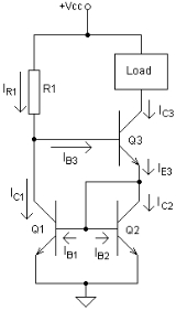
A Wilson current mirror or Wilson current source is a circuit configuration designed to provide a constant current source
or sink. It is named after George Wilson, an integrated circuit
design engineer
working for Tektronix
. Rumor has it that Wilson came up with this configuration after being challenged by Barrie Gilbert
to come up with a useful new circuit that used three active devices.
 Assumptions:
Therefore, IC1 = IC2 (= IC) and IB1 = IB2 (= IB) ... (1)
Base current of Q3 is given by,
 ... (2)
and emitter current by,
 ... (3)
From the schematic, it is evident that IE3 = IC2 + IB1 + IB2 ... (4)
substituting for IC2, IB1 and IB2 from (1) in (4),
IE3 = IC + 2.IB ... (5)
so,
 ... (6)
substituting for IE3 from (3),
rearranging,
 ... (7)
Current through R1 is given by,
IR1 = IC1 + IB3 ... (8)
But, IC1 = IC2 = IC
Substituting for IC from (7) in (8) and since we get,
 ... (9)
Therefore, ... (10)
And finally,
 ... (11)
From the above equation we can see that if
And the output current (assuming the base-emitter voltage of all transistors to be 0.7 V) is calculated as,
The output current is thus substantially dependent only on VCC and R1 and the circuit acts as a constant current source
; that is, the current remains constant with variations in load. However, variations in VCC will be reflected in variations in the output current.
thereby ensuring that the output current IC3 is almost equal to the reference or input current IR1. It also has a very high output impedance
.
 Adding a fourth transistor to the Wilson current mirror (as shown in the diagram to the right) improves its linearity at higher current levels. It accomplishes this by equalizing the collector voltages of Q1 and Q2 at 1 Vbe. This leaves the finite beta and voltage differences of each of Q1 and Q2 as the remaining unbalancing influences in the mirror.
Furthermore, the power dissipated in the junctions of Q1 and Q2 will be close to the same which tends to cancel the thermal effects on Vbe.
Current source
A current source is an electrical or electronic device that delivers or absorbs electric current. A current source is the dual of a voltage source. The term constant-current sink is sometimes used for sources fed from a negative voltage supply...
or sink. It is named after George Wilson, an integrated circuit
Integrated circuit
An integrated circuit or monolithic integrated circuit is an electronic circuit manufactured by the patterned diffusion of trace elements into the surface of a thin substrate of semiconductor material...
design engineer
Design engineer
Design Engineer is a general term that covers multiple engineering disciplines including electrical, mechanical, industrial design and civil engineering, architectural engineers in the U.S...
working for Tektronix
Tektronix
Tektronix, Inc. is an American company best known for its test and measurement equipment such as oscilloscopes, logic analyzers, and video and mobile test protocol equipment. In November 2007, Tektronix became a subsidiary of Danaher Corporation....
. Rumor has it that Wilson came up with this configuration after being challenged by Barrie Gilbert
Barrie Gilbert
Barrie Gilbert was born in 1937 in Bournemouth, England. He is well-known for his invention of numerous analog circuit concepts, holding over 100 patents worldwide, and for the discovery of the Translinear Principle and a class of related topologies loosely referred to as the Gilbert cell, one of...
to come up with a useful new circuit that used three active devices.
Circuit Analysis
- All transistors have the same current gain β.
- Q1 and Q2 are matched, so their collector currents are equal.
Therefore, IC1 = IC2 (= IC) and IB1 = IB2 (= IB) ... (1)
Base current of Q3 is given by,
... (2)and emitter current by,
... (3)From the schematic, it is evident that IE3 = IC2 + IB1 + IB2 ... (4)
substituting for IC2, IB1 and IB2 from (1) in (4),
IE3 = IC + 2.IB ... (5)
so,
... (6)substituting for IE3 from (3),
rearranging,
... (7)Current through R1 is given by,
IR1 = IC1 + IB3 ... (8)
But, IC1 = IC2 = IC
Substituting for IC from (7) in (8) and since
we get, ... (9)Therefore,
... (10)And finally,
... (11)From the above equation we can see that if
And the output current (assuming the base-emitter voltage of all transistors to be 0.7 V) is calculated as,
The output current is thus substantially dependent only on VCC and R1 and the circuit acts as a constant current source
Current source
A current source is an electrical or electronic device that delivers or absorbs electric current. A current source is the dual of a voltage source. The term constant-current sink is sometimes used for sources fed from a negative voltage supply...
; that is, the current remains constant with variations in load. However, variations in VCC will be reflected in variations in the output current.
Advantages over other configurations
This circuit has the advantage of virtually eliminating the base current mis-match of the conventional current mirrorCurrent mirror
A current mirror is a circuit designed to copy a current through one active device by controlling the current in another active device of a circuit, keeping the output current constant regardless of loading. The current being 'copied' can be, and sometimes is, a varying signal current...
thereby ensuring that the output current IC3 is almost equal to the reference or input current IR1. It also has a very high output impedance
Electrical impedance
Electrical impedance, or simply impedance, is the measure of the opposition that an electrical circuit presents to the passage of a current when a voltage is applied. In quantitative terms, it is the complex ratio of the voltage to the current in an alternating current circuit...
.
Further improvement
Furthermore, the power dissipated in the junctions of Q1 and Q2 will be close to the same which tends to cancel the thermal effects on Vbe.