
Shock Pulse Method
Encyclopedia
Shock Pulse Method, also known as SPM, is a patented technique for using signals from rotating rolling bearings as the basis for efficient condition monitoring
of machines. From the innovation of the method in 1969 it has now been further developed and broadened and is now a worldwide accepted philosophy for condition monitoring of rolling bearings and machine maintenance.
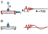
 Consider a metal ball hitting a metal bar. At the moment of impact, a pressure wave
spreads through the material of both bodies (1). The wave is transient (quickly dampens out). When the wave front hits the shock pulse transducer, it will cause a dampened oscillation of the transducer's reference mass. The peak amplitude is a function of the impact velocity (v).
During the next phase of the collision, both bodies start to vibrate (2). The frequency of this vibration is a function of the mass and the shape of the colliding bodies.
 A shock pulse transducer reacts with a large amplitude oscillation to the weak shock pulses, because it is excited at its resonance frequency
of 32 kHz. Machine vibration, of a much lower frequency, is filtered out.
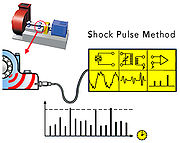
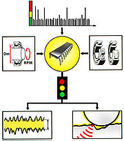
The first frame shows the symbol for a transducer and, below, the vibration signal from the machine, with superimposed transients at the resonance frequency, caused by shock pulses. The second frame shows the electric filter which passes a train of transients at 32 kHz. Their amplitudes depend on the energy of the shock pulses. The transients are converted into analogue electric pulses. The last frame shows the converted shock pulse signal from the bearing, now consisting of a rapid sequence of stronger and weaker electric pulses.
 The filtered transducer signal reflects the pressure variation in the rolling interface of the bearing. When the oil film in the bearing is thick, the shock pulse level is low, without distinctive peaks. The level increases when the oil film is reduced, but there are still no distinctive peaks. Damage causes strong pulses at irregular intervals.
, at two levels. A micro processor evaluates the signal. It needs input data defining the bearing type (ISO number) and the rolling velocity (RPM and bearing diameter).
Surface damages in a bearings causes a large increase in shock pulse strength, combined with a marked change in the characteristics between stronger and weaker pulses. Shock values are thus immediately translated into measurements of relative oil film thickness or surface damage, whichever applies.
Condition monitoring
Condition monitoring is the process of monitoring a parameter of condition in machinery, such that a significant change is indicative of a developing failure. It is a major component of predictive maintenance. The use of conditional monitoring allows maintenance to be scheduled, or other actions...
of machines. From the innovation of the method in 1969 it has now been further developed and broadened and is now a worldwide accepted philosophy for condition monitoring of rolling bearings and machine maintenance.
Difference between shock pulse and vibration
P-wave
P-waves are a type of elastic wave, also called seismic waves, that can travel through gases , solids and liquids, including the Earth. P-waves are produced by earthquakes and recorded by seismographs...
spreads through the material of both bodies (1). The wave is transient (quickly dampens out). When the wave front hits the shock pulse transducer, it will cause a dampened oscillation of the transducer's reference mass. The peak amplitude is a function of the impact velocity (v).
During the next phase of the collision, both bodies start to vibrate (2). The frequency of this vibration is a function of the mass and the shape of the colliding bodies.
Processing shock pulse signals
Resonance
In physics, resonance is the tendency of a system to oscillate at a greater amplitude at some frequencies than at others. These are known as the system's resonant frequencies...
of 32 kHz. Machine vibration, of a much lower frequency, is filtered out.
The first frame shows the symbol for a transducer and, below, the vibration signal from the machine, with superimposed transients at the resonance frequency, caused by shock pulses. The second frame shows the electric filter which passes a train of transients at 32 kHz. Their amplitudes depend on the energy of the shock pulses. The transients are converted into analogue electric pulses. The last frame shows the converted shock pulse signal from the bearing, now consisting of a rapid sequence of stronger and weaker electric pulses.
Shock pulse patterns
Measuring Operating Condition
The Shock Pulse meters measure the shock signal on a decibel scaleDecibel
The decibel is a logarithmic unit that indicates the ratio of a physical quantity relative to a specified or implied reference level. A ratio in decibels is ten times the logarithm to base 10 of the ratio of two power quantities...
, at two levels. A micro processor evaluates the signal. It needs input data defining the bearing type (ISO number) and the rolling velocity (RPM and bearing diameter).
Surface damages in a bearings causes a large increase in shock pulse strength, combined with a marked change in the characteristics between stronger and weaker pulses. Shock values are thus immediately translated into measurements of relative oil film thickness or surface damage, whichever applies.